
Related Manuals for Atlas Copco XAMS 407 CD


Summary of Contents for Atlas Copco XAMS 407 CD
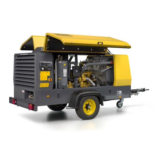
- Page 1 XAMS 407 CD - XAMS 850 CD7 XATS 377 CD - XATS 800 CD7 Engine CAT C7 XAHS 347 CD - XAHS 710 CD7 XAVS 307 CD - XAVS 650 CD7 Instruction Manual For Portable Compressors English...
- Page 3 Instruction Manual for Portable Compressors XAMS 407 CD - XAMS 850 CD7 XATS 377 CD - XATS 800 CD7 XAHS 347 CD - XAHS 710 CD7 XAVS 307 CD - XAVS 650 CD7 Printed matter N° 2954 3190 00 ATLAS COPCO - PORTABLE AIR DIVISION www.atlascopco.com...
- Page 4 The manufacturer does not accept any liability for any damage arising for modifications, additions or conversions made without the manufacturer's approval in writing. While every effort has been made to ensure that the information in this manual is correct, Atlas Copco does not assume responsibility for possible errors.
-
Page 5: Table Of Contents
Table of contents Preface 4.3.4 Xc2002™ Menu Overview....33 4.3.5 Xc2002™ Menu Description....37 Please read the following instructions carefully Safety precautions ........7 4.3.6 During operation ........39 before starting to use your compressor. 4.3.7 Operations overview ......39 Introduction .......... - Page 6 5.11.1 Topping up without draining Problem solving ........66 from the cooling system ......54 Available options ........69 5.11.2 Topping up after limited quantity draining from the cooling system... 55 Technical specifications ......71 5.11.3 Replacing the coolant......56 Torque values ..........
-
Page 7: Safety Precautions
To be read attentively and acted accordingly before towing, lifting, operating, performing maintenance or repairing the compressor. INTRODUCTION The policy of Atlas Copco is to provide the users of It is the responsibility of management to appoint Take necessary steps to keep unauthorized persons... -
Page 8: General Safety Precautions
The manufacturer does not accept any liability for any GENERAL SAFETY PRECAUTIONS Care shall be taken to avoid damage to safety damage arising from the use of non-original parts and valves other pressure-relief devices, The owner is responsible for maintaining the unit for modifications, additions or conversions made especially to avoid plugging by paint, oil coke or in a safe operating condition. -
Page 9: Safety During Transport And Installation
13 If the warning light on the ABS module or in the Place the unit on level ground and apply the bends in lifting cables, chains or ropes. vehicle lights up, please contact Atlas Copco. parking brake before disconnecting the unit from Helicopter lifting is not allowed. - Page 10 13 Never refill fuel while the unit is running, unless The air line end connected to the outlet valve relatively short times, about the need to wear otherwise stated in the Atlas Copco Instruction must be safeguarded with a safety cable, attached ear protectors, Book (AIB).
-
Page 11: Safety During Maintenance And Repair
(check valves) to isolate recommended or approved by Atlas Copco or the pressure systems. In addition, a warning sign machine manufacturer. Ascertain that the bearing a legend such as ”work in progress; do selected lubricants comply with all applicable not open”... -
Page 12: Tool Applications Safety
15 Protect the engine, alternator, air intake filter, 23 Make sure that oil, solvents and other substances electrical and regulating components, etc., to likely to pollute the environment are properly prevent moisture ingress, e.g. when steam- disposed of. cleaning. 24 Before clearing the unit for use after maintenance 16 When performing any operation involving heat, or overhaul, check that operating pressures, flames or sparks on a machine, the surrounding... -
Page 13: Specific Safety Precautions
If the set pressure must be altered then use only When batteries are being charged, an explosive correct parts supplied by Atlas Copco and in - the minimum working temperature Tmin in °C gas mixture forms in the cells and might escape accordance with the instructions available for the (°F),... -
Page 14: Leading Particulars
Cooling system Compressor oil system The XAMS 407 CD - XAMS 850 CD7 is a silenced, single-stage, oil-injected screw compressor, built for The engine is provided with a liquid-cooler and The oil is boosted by air pressure. The system has no intercooler and the compressor is provided with an oil a nominal effective working pressure of 8.6 bar... - Page 15 Frame and axles Serial number The compressor/engine unit is supported by rubber buffers in the frame. The standard compressor has an adjustable or fixed towbar with brakes. The braking system consists of an integrated parking brake and overrunbrake. When driving backwards the overrunbrake is not engaged automatically.
-
Page 16: Main Parts
Main Parts (FF) (EP) (TB) (FFac) (IC) (OFce) (RV) (SV) (AFe) (AFce) (FCc) (OC) (FLS) (FCft) (CT) (FT) (BS) (LV) (SN) (CE) (OFe) (MPV) (AOV) (AR) (FPco) (CP) (OLG) (ES) - 16 -... - Page 17 Reference Name Reference Name Alternator Fuel Tank AFce Air Filter (compressor element) Intercooler Air Filter (engine) Loading Valve Air Outlet Valves Minimum Pressure Valve Air Receiver Oil Cooler Battery OFce Oil Filter (compressor element) Battery Switch Oil Filter (engine) Compressor Element Oil Level Gauge Control Panel Radiator...
-
Page 18: Compressor Regulating System
COMPRESSOR REGULATING SYSTEM OVERVIEW (AFe) (AFS) (OC) (AFce) (RPS) (TV) (UA) (OFce) (BN) (CE) (TBV) (BVof) (BOV) (CV) (TS) (LV) (DPcv) (OSV) (WPS) (DPosv) (RV) (SV) (AR) (FPco) (SL) (MPV) (TS) (FR) (AOV) (OS) (OLG) (DPar) - 18 -... - Page 19 Reference Name Reference Name AFce Air Filter (compr. element) Oil Level Gauge Air Filter (engine) Oil Separator Air Filter Switch Oil Stop Valve Air Outlet Valves Pressure Sensor Air Receiver Regulating Pressure Sensor Blow Off Valve Regulating Valve BVof Bypass Valve oil filter Safety Cartridge Coupling Scavenge Line...
-
Page 20: Air Flow
AIR FLOW Air drawn through the airfilter (AFce) into the compressor element (CE) is compressed. At the element outlet, compressed air and oil pass into the air receiver/oil separator (AR/OS). (AFce) The check valve (CV) prevents blow-back of compressed air when the compressor is stopped. In the air receiver/oil separator (AR/OS), most of the oil is removed from the air/oil mixture. -
Page 21: Oil System
OIL SYSTEM The lower part of the air receiver (AR) serves as oil tank. Air pressure forces the oil from the air receiver/oil (OC) separator (AR/OS) through the oil cooler (OC), the oil filters (OF) and the oil stop valve (OSV) to the compressor element (CE). -
Page 22: Continuous Regulating System
CONTINUOUS REGULATING SYSTEM (TV) (UA) (CE) (BOV) (RV) (AR) - 22 -... - Page 23 The compressor is provided with a continuous If the air consumption is less than the maximum air regulating system and a blow-off valve (BOV) which output, air receiver pressure increases and the is integrated in the unloader assembly (UA). The regulating valve supplies control air to throttle valve valve is closed during operation by outlet pressure of (TV) to reduce the air output and holds air receiver...
-
Page 24: Electric System
ELECTRIC SYSTEM Circuit diagram (9822 0937 90) Connection Box Canopy 13 14 23 25 26 27 32 33 34 35 36 Battery + 38 40 41 43 49 54 CAN L CAN GND CAN H Battery - Cubicle Canopy - 24 -... - Page 25 Reference Name Reference Name Diode 1 CAN-L CAN LOW Circuit Breaker 2 CAN-GND CAN Shield Battery 3 CAN-H CAN high Alternator 4 GND Common for 5..7 (GND) Start Relay 7 Input Low Coolant Shutdown Relay - Starter Motor 12 GND Common for 13..18 (24Vdc) Level Switch - Coolant level 13 DI-01...
-
Page 26: Markings And Information Labels
Fork lifting permitted. Read the instruction manual before Electrocution hazard. Don’t lift here. starting. Read the instruction manual before Atlas Copco synthetic compressor oil. Service every 24 hours. lifting. Atlas Copco mineral engine oil. Warning! Part under pressure. Filler cap coolant. -
Page 27: Operating Instructions
Operating instructions PARKING INSTRUCTIONS PARKING, TOWING AND LIFTING INSTRUCTIONS Safety precautions The operator is expected to apply all relevant Safety precautions. Attention Before putting the compressor in to use, check the brake system as described in section Brake shoe adjustment. After the first 100 km travel: Fixed towbar with jockey wheel and brakes Parking position of jockey wheel (adjustable towbar) -
Page 28: Towing Instructions
TOWING INSTRUCTIONS Label on towbar, towing instructions Towing position of jockey wheel Push hand brake lever completely downwards and Before towing the compressor, ensure Before moving the compressor, switch it connect breakaway cable (1) to the vehicle. Secure that the towing equipment of the vehicle off. -
Page 29: Height Adjustment
HEIGHT ADJUSTMENT LIFTING INSTRUCTIONS (with adjustable towbar) • Remove spring pin (1). • Release locking nut (2) with support tools (extension tube 3). • Adjust required height of the towbar. • Tighten locking nut (2) by hand first. • Secondly tighten locking nut (2) with a tightening torque corresponding to table. -
Page 30: Starting / Stopping
STARTING / STOPPING 9. Attach the air line(s) to the closed air outlet BEFORE STARTING valve(s). Connect the safety chain. 1. Before initial start-up, prepare battery for No external force may be applied to the operation if not already done. See section air outlet valve(s), e.g. -
Page 31: Battery Switch
BATTERY SWITCH The compressor is equipped with a battery switch. When the compressor is not in use this switch must always be in the “OFF” position. It is not allowed to use this switch as an emergency switch or for stopping the compressor. -
Page 32: Control Panel
CONTROL PANEL XC2002™ MODULE Pushbutton and LED functions Following pushbuttons are used on the Xc2002™ (ON/OFF) ENTER: Used to select and confirm changed settings in the Parameters list. BACK: Is used to leave the Alarm pop-up window, to leave the Parameter list and to leave menu's without change UP: Is used to scroll through the display information and to adjust... -
Page 33: Xc2002™ Menu Overview
Following LED´s are used on the Xc2002™ XC2002™ MENU OVERVIEW - Oil pressure At Xc2002™, the LCD will show the following --bar information through the display views: 00000.h 1. in Normal condition (scroll through the information using UP and DOWN): This view shows the engine oil pressure and the - Controller type &... - Page 34 - Battery voltage - Xc2002 Event LOG #01 - Parameter list - Xc2002 Event LOG #02 Parameter Battery 12.0V Xc 2002 EVENT LOG #01 00000.h New software dl Time: 000000 h This view shows the battery voltage and the This view shows a number of Parameter settings running hours.
- Page 35 - Unit - ST1 Reset - Extra views display - ST2 Reset Extra Views Unit ST1 Reset C/bar C/bar F/psi This menu can be accessed to select units of This view shows the extra views available in the measure in either metric (°C, bar) or imperial (°F, controller.
- Page 36 - Air Inlet temperature - Regulating pressure E|C A. inlet --°C RegP 0.37bar temperature 00000.h 00000.h This view shows the air temperature at inlet and This view shows the regulating pressure and the the running hours. running hours. See also "Parameter list" on page 34 for selection See also "Parameter list"...
-
Page 37: Xc2002™ Menu Description
2. in Alarm condition (scroll through the These special statuses are: Alarm Display (pop-up window) information using UP and DOWN): In case an Alarm occurs, a pop-up window will - a list of all active Alarms automatically be displayed for as long as the alarm is •... - Page 38 List of possible alarms: LOG list Fail Classes The unit will keep an event log of the latest 15 events. All activated alarms of the Xc2002™ have their own predefined fail class. 1. LOW OIL Events are: PRESSURE All alarms are enabled according to one of these three •...
-
Page 39: During Operation
DURING OPERATION 4. Avoid the engine running out of fuel. (RV) Nevertheless, if this happens, fill the fuel tank and prime the fuel system to speed up starting (see section Priming instructions). When the engine is running the air outlet valves (ball valves) must always be put in fully opened or fully closed position. -
Page 40: Power On / Off
POWER ON / OFF STARTING WARMING UP (ON/OFF) Press the button "I" (2) When the engine started the warming up is started. The compressor can be loaded after the compressor • When the ambient temperature is below has reached a temperature of 40°C, or after a warming 10°C ( 50°F) the display will show: up period of 5 minutes. -
Page 41: Stopping
STOPPING To turn off the compressor first press the button "0" EMERGENCY STOP (1). The engine will run some time at minimum speed (ON/OFF) The emergency stop button (2) is only to be used in to cool down and will stop finally. emergency situations;... -
Page 42: Fault Codes
FAULT CODES There are several parameters that are continuously The message displayed can be a warning, a shut down watched. or a start failure. When one of these parameters exceeds its specified limit the compressor will react depending the present status of the control box. -
Page 43: Maintenance
If the compressor is going to be stored Service Paks minimize downtime and keep your without running from time to time, maintenance budget low. protective measures must be taken. Order Service Paks at your local Atlas Copco dealer. - 43 -... -
Page 44: Preventive Maintenance Schedule For The Compressor
Every 6 months or Yearly or every initial start-up 500 hours 1000 hours XAMS 407 CD - XAMS 850 CD7, supplied with unit 2912 4482 05 2912 4483 06 XATS 377 CD - XATS 800 CD7, XAHS 347 CD - XAHS 710 CD7,... - Page 45 Maintenance schedule Daily 50 hours after initial Every 6 months or Yearly or every (continuation of page 44) start-up 500 hours 1000 hours Intercooler Clean Clean Torque of wheel nuts Check Check Check Brake system (if installed) Check/Adjust Check/Adjust Check/Adjust Safety valve (10) Test Door hinges...
- Page 46 The quality of the fuel determines the frequency of renewal. 8. See section Oil specifications. 9. The following part numbers can be ordered from Atlas Copco to check on inhibitors and freezing point: • 2913 0028 00 refractometer •...
-
Page 47: Oil Specifications
-5°C and 30°C PAROIL M PAROIL 15W40 PAROIL S Only use mineral based compressor oil PAROIL M in XAMS 407 CD - XAMS between -20°C and -5°C PAROIL S PAROIL 5W30 850 CD7, XATS 377 CD - XATS 800 CD7, XAHS 347 CD - XAHS 710 CD7 and XAVS 307 CD - XAVS 650 CD7. -
Page 48: Engine Oil
ENGINE OIL PAROIL from Atlas Copco is the ONLY oil tested PAROIL contains high quality anti-oxidants to PAROIL 5W30 is a synthetic ultra high performance and approved for use in all engines built into Atlas control deposits, sludge and contaminants that tend to diesel engine oil with a high viscosity- index. -
Page 49: Oil Level Check
OIL LEVEL CHECK CHECK COMPRESSOR OIL LEVEL CHECK ENGINE OIL LEVEL Also consult the Engine Operation Manual for the oil specifications, viscosity recommendations and oil change intervals. For intervals, see Preventive maintenance schedule for the compressor. Check engine oil level according to the instructions in the Engine Operation Manual and if necessary top up with oil. -
Page 50: Oil And Oil Filter Change
When operating in high ambient temperatures, in very dusty or high humidity conditions, it is recommended to change the oil more frequently. Never add more oil. Overfilling results in oil consumption. In this case, contact Atlas Copco. - 50 -... -
Page 51: Topping Up The Compressor Oil
TOPPING UP THE COMPRESSOR OIL COOLANT SPECIFICATIONS It is strongly recommended to use Atlas Copco branded coolant. The use of the correct coolant is important for good heat transfer and protection of liquid-cooled engines. Coolants used in these engines must be mixtures of good quality water (distilled or de-ionised), special coolant additives and if necessary freeze protection. -
Page 52: Parcool Eg
50/50 your health and the environment. Longer service life currently in use in Atlas Copco compressors and dilution ratio, for antifreeze protection guaranteed to reduces the amount of coolant produced and needing generators. -
Page 53: Handling Parcool Eg
PARCOOL EG is compatible with most other • A refractometer can be ordered from Atlas Copco injury from the splash of hot coolant. coolants based on ethylene glycol, but you only get the benefits of 5 years protection when its used on its with part number 2913 0028 00. -
Page 54: Topping Up Without Draining From The Cooling System
TOPPING UP WITHOUT DRAINING FROM THE COOLING SYSTEM The quantity of PARCOOL EG Concentrate to be topped up can be estimated with the following formula and/or graph: Corrections concentrate in measured system towards 50% volume by using PARCOOL EG Concentrate Example: PN: 1604 8159 00 Liter... -
Page 55: Topping Up After Limited Quantity Draining From The Cooling System
TOPPING UP AFTER LIMITED QUANTITY DRAINING FROM THE COOLING SYSTEM The quantity of PARCOOL EG Concentrate to be topped up after draining a calculated volume from the cooling system, can be estimated with the following formula and/or graph: Corrections concentrate in measured system towards 50% volume by using PARCOOL EG Concentrate Example: PN: 1604 8159 00 Liter... -
Page 56: Replacing The Coolant
Clean by air jet in the direction of the arrow. operation temperature is reached. Turn off the engine and allow to cool. • From the Atlas Copco Instruction book, determine the amount of PARCOOL EG required. • Mix concentrate and water before filling. -
Page 57: Battery Care
When a compressor element is due for overhaul, it electrolyte. ELECTROLYTE needs to be done by Atlas Copco. This guarantees the • Refit plugs and/or cover. use of genuine parts and correct tools with care and • Place the battery in the compressor. -
Page 58: Adjustments And Servicing Procedures
Adjustments and servicing procedures ADJUSTMENT OF THE CONTINUOUS REGULATING SYSTEM The working pressure is determined by the tension of the spring in the regulating valve (RV). This tension can be increased to raise the pressure and decreased to lower it by turning the adjusting wheel clockwise and anti-clockwise respectively. -
Page 59: Air Filter Engine/Compressor
AIR FILTER ENGINE/COMPRESSOR MAIN PARTS CLEANING THE DUST TRAP Remove dust daily. The Atlas Copco air filters are specially To remove dust from the dust trap pinch the vacuator designed for the application. The use of valve (6) several times. -
Page 60: Replacing The Air Filter Element
In order to clean, position a pipe with an end bent by REPLACING THE AIR FILTER ELEMENT New elements must also be inspected for tears or approx. 90° on the end of a compressed-air pistol. The punctures before installation. pipe must be long enough to reach the bottom of the Discard the element (4) when damaged. -
Page 61: Air Receiver
AIR RECEIVER SAFETY VALVE FUEL SYSTEM PRIMING INSTRUCTIONS All adjustments or repairs are to be done by an authorized representative of the valve supplier, see section Specific safety Fuel leaked or spilled onto hot surfaces precautions. or electrical components can cause a fire. To help prevent possible injury, turn the “ON/OFF”... -
Page 62: Draining Instructions
DRAINING INSTRUCTIONS Replacing the filter elements: (to be updated) Installation instructions: 1. Drain fuel from the bowl. 2. Remove filter (2, 3), filterelement (4) and separate bowl (2) from element (3). 3. Apply film of gas oil to new bowl seat. 4. -
Page 63: Brake Adjustment
BRAKE ADJUSTMENT BRAKE SHOE ADJUSTMENT Before jacking up the compressor, connect it to a towing vehicle or attach a weight of minimum 50 kg (110 lb) to the towbar. Check the thickness of the brake lining. 1. Lift and support the compressor. Make sure that all brakes (overrunbrake and hand brake) are off. -
Page 64: Audit Procedure Of Brake Cable Adjustment
AUDIT PROCEDURE OF BRAKE CABLE ADJUSTMENT X-Y=35 Hand brake (adjustable towbar) Hand brake (fixed towbar) 1. Check if the towing eye rod of the overrun brake mechanism is in the outmost position. 2. Hand brake lever is just over its top. 3. -
Page 65: Brake Cable Adjustment
BRAKE CABLE ADJUSTMENT TEST PROCEDURE OF BRAKE CABLE ADJUSTMENT 3 mm - 5 mm Hand brake lever downward - brake not operated (adjustable Brake cable arrangement 1. Pull main brake cable downwards. towbar) 2. The brake cables need 3 mm (0.12 in) to 5 mm (0.2 in) margin (to see on different colors on 1. -
Page 66: Problem Solving
Choked air filter elements (AF). Remove and inspect elements. Clean or replace, if necessary. Regulating valve (RV) defective. Have regulating valve removed and inspected by an Atlas Copco Service representative. Blow down valve stuck in open position. Check and correct as necessary. - Page 67 Possible faults Corrective actions Regulating valve (RV) opens too late or its ball valve spring is broken. Have regulating valve removed and inspected by an Atlas Copco Service representative. Air leaks in regulating system. Check hoses and their fittings. Stop leaks; replace leaking hoses.
- Page 68 Check and correct if necessary. Oil stop valve malfunctioning. Remove and inspect valve. Oil separator element (OS) clogged. Have element removed and inspected by an Atlas Copco Service representative. Alternator precautions 1. Never reverse the polarity of the battery or the alternator.
-
Page 69: Available Options
Available options Support SCANDIC cold weather package (to -10°C) ARCTIC cold start package (-25°C to –30°C) - OTM only A rigid support mounted version for rough The SCANDIC cold weather package consist of a construction conditions with the possibility to be heater plug, installed in the air-inlet to the engine, a The ARCTIC cold weather package is a combination mounted on a truck. - Page 70 Reheater Customer colour canopy (1 colour) For applications with a need for dry unsaturated air or Special colour will apply on all external canopy parts where ambient conditions cause risk of freezing tools or all internal parts visible from the outside, and a reheater can be installed.
-
Page 71: Technical Specifications
Technical specifications TORQUE VALUES GENERAL TORQUE VALUES CRITICAL TORQUE VALUES The following tables list the recommended torques applied for general applications Assemblies Torque value (Nm / lbf.ft) at assembly of the compressor. Axles to frame: Wheel nuts 270 (199.26) For hexagon screws and nuts with strength grade 8.8 Bolts, front axle/frame 205 (151.29) Bolts, rear axle/frame... -
Page 72: Compressor / Engine Specifications
COMPRESSOR / ENGINE SPECIFICATIONS REFERENCE CONDITIONS Designation XAMS 407 CD - XATS 377 CD - XAHS 347 CD - XAVS 307 CD - XAMS 850 CD7 XATS 800 CD7 XAHS 710 CD7 XAVS 650 CD7 Absolute inlet pressure bar(e) 14.5 14.5... -
Page 73: Altitude Unit Performance Curve
ALTITUDE UNIT PERFORMANCE CURVE Max. allowable working pressure as a function altitude and ambient temperature. TEMPERATURE IN °F TEMPERATURE IN °F 4000 13 124 4000 13 124 3000 9 843 3000 9 843 8.6 bar 10.3 bar 125 psi 149 psi 2000 6 562 2000... -
Page 74: Altitude Unit Performance Curve
ALTITUDE UNIT PERFORMANCE CURVE Max. allowable working pressure as a function altitude and ambient temperature. TEMPERATURE IN °F TEMPERATURE IN °F 4000 13 124 4000 13 124 3000 9 843 3000 9 843 12 bar 14 bar 174 psi 203 psi 2000 6 562 2000... -
Page 75: Performance Data
PERFORMANCE DATA At reference conditions, if applicable, and at normal shaft speed, unless otherwise stated. Designation XAMS 407 CD - XATS 377 CD - XAHS 347 CD - XAVS 307 CD - XAMS 850 CD7 XATS 800 CD7 XAHS 710 CD7... - Page 76 Designation XAMS 407 CD - XATS 377 CD - XAHS 347 CD - XAVS 307 CD - XAMS 850 CD7 XATS 800 CD7 XAHS 710 CD7 XAVS 650 CD7 - at unload Fuel expert kg/h 16.8 17.6 18.3 18.8 lb/h 37.0...
-
Page 77: Design Data
Compressor element Designation Number of compression stages Engine Designation XAMS 407 CD - XAMS 850 CD7, Designation XAMS 407 CD - XAMS 850 CD7, XATS 377 CD - XATS 800 CD7, XATS 377 CD - XATS 800 CD7, XAHS 347 CD - XAHS 710 CD7,... - Page 78 Compressor Compressor dimensions with brakes and adjustable towbar Designation XAMS 407 CD - XAMS 850 CD7, Designation All units XATS 377 CD - XATS 800 CD7, Length 4945 XAHS 347 CD - XAHS 710 CD7, 197.8 XAVS 307 CD - XAVS 650 CD7...
-
Page 79: Dataplate
Dataplate Company code (1) (2) Product code Unit serial number Name of the manufacturer EEC or national type approval number Vehicle identification number A Maximum permitted total weight of the vehicle B Maximum permitted axle load (10) C Maximum permitted load on the towing eye (11) Model Working pressure... -
Page 80: Legislation Size 2 Lp
Legislation Size 2 LP PARTS, SUBJECTED TO PRESSURE EQUIPMENT DIRECTIVE 97/23/EC, CAT. II AND ABOVE Safety valve: cat. IV XAMS 407 CD - XATS 377 CD - XAHS 347 CD - XAVS 307 CD - XAMS 850 CD7 XATS 800 CD7... -
Page 81: Parts, Subjected To Cat. I And Covered By The Machine Directive 89/392/Ec
PARTS, SUBJECTED TO CAT. I AND COVERED BY THE MACHINE DIRECTIVE 89/392/EC All other parts PARTS, SUBJECTED TO ART. I, PARAGRAPH 3.3 All other parts - 81 -... -
Page 82: Disposal
(for example sand, sawdust) and recyclable materials. dispose it according the applicable local disposal Your Atlas Copco compressor consists for the most regulations. Do not drain into the sewage system or part of metallic materials, that can be remelted in surface water. -
Page 83: Maintenance Log
Maintenance Log Compressor ..................Customer ....................Serial number........................................Service hours Maintenance action Date By initials - 83 -... - Page 84 Notes: - 84 -...
- Page 85 Notes: - 85 -...
- Page 86 Notes: - 86 -...
Need help?
Do you have a question about the XAMS 407 CD and is the answer not in the manual?
Questions and answers