Table of Contents
Advertisement
Advertisement
Table of Contents

Related Manuals for thomann T.racks DSP 26

Summary of Contents for thomann T.racks DSP 26
- Page 1 DSP 26 digital speaker management system user manual...
- Page 2 Musikhaus Thomann Thomann GmbH Hans-Thomann-Straße 1 96138 Burgebrach Germany Telephone: +49 (0) 9546 9223-0 E-mail: info@thomann.de Internet: www.thomann.de 29.06.2017, ID: 341074 (V2)
-
Page 3: Table Of Contents
Table of contents Table of contents General notes............................... 5 1.1 Further information........................... 6 1.2 Notational conventions........................7 1.3 Symbols and signal words....................... 8 Safety instructions..........................10 Features............................... 14 Installation and starting up........................ 15 Connections and controls........................16 Operating..............................21 6.1 UTILITY menu............................ 22 6.2 INPUT A/B menu.......................... - Page 4 Table of contents Plug and connection assignment....................52 Cleaning............................... 54 Protecting the environment......................55 digital speaker management system...
-
Page 5: General Notes
General notes General notes This manual contains important instructions for the safe operation of the unit. Read and follow the safety instructions and all other instructions. Keep the manual for future reference. Make sure that it is available to all those using the device. If you sell the unit please make sure that the buyer also receives this manual. -
Page 6: Further Information
General notes 1.1 Further information On our website (www.thomann.de) you will find lots of further information and details on the following points: Download This manual is also available as PDF file for you to download. Use the search function in the electronic version to find the topics of Keyword search interest for you quickly. -
Page 7: Notational Conventions
General notes 1.2 Notational conventions This manual uses the following notational conventions: Letterings The letterings for connectors and controls are marked by square brackets and italics. Examples: [VOLUME] control, [Mono] button. Displays Texts and values displayed on the device are marked by quotation marks and italics. Examples: ‘24ch’... -
Page 8: Symbols And Signal Words
General notes 1.3 Symbols and signal words In this section you will find an overview of the meaning of symbols and signal words that are used in this manual. Signal word Meaning DANGER! This combination of symbol and signal word indicates an immediate dangerous situation that will result in death or serious injury if it is not avoided. - Page 9 General notes Warning signs Type of danger Warning – high-voltage. Warning – danger zone. DSP 26...
-
Page 10: Safety Instructions
Safety instructions Safety instructions Intended use This device serves sound control and distribution of incoming audio signals to the connected speakers. Use the device only as described in this user manual. Any other use or use under other operating conditions is considered to be improper and may result in personal injury or property damage. - Page 11 Safety instructions DANGER! Electric shock caused by high voltages inside Within the device there are areas where high voltages may be present. Never remove any covers. There are no user-serviceable parts inside. Do not use the device if covers, protectors or optical components are missing or damaged.
- Page 12 Safety instructions CAUTION! Possible hearing damage With loudspeakers or headphones connected, the device can produce volume levels that may cause temporary or permanent hearing impairment. Do not operate the device permanently at a high volume level. Decrease the volume level immediately if you experience ringing in your ears or hearing impairment.
- Page 13 Safety instructions NOTICE! Operating conditions This device has been designed for indoor use only. To prevent damage, never expose the device to any liquid or moisture. Avoid direct sunlight, heavy dirt, and strong vibrations. NOTICE! Power supply Before connecting the device, ensure that the input voltage (AC outlet) matches the voltage rating of the device and that the AC outlet is protected by a residual current circuit breaker.
-
Page 14: Features
Features Features Two input channels Six output channels Digital 24-bit signal processors RS485 interface USB port Suitable for installation in 19-inch racks (1 RU) digital speaker management system... -
Page 15: Installation And Starting Up
Installation and starting up Installation and starting up Unpack and carefully check that there is no transportation damage before using the unit. Keep the equipment packaging. To fully protect the device against vibration, dust and moisture during transportation or storage use the original packaging or your own packaging material suitable for transport or storage, respectively. -
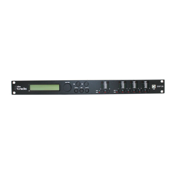
Page 16: Connections And Controls
Connections and controls Connections and controls Front panel digital speaker management system... - Page 17 Connections and controls 1 Display 2 [NAV/PM1] Rotary switch for setting of values in submenus. 3 [PM2] Rotary switch for setting of values in submenus. 4 [PM3] Rotary switch for setting of values in submenus. 5 [ENTER] Button to confirm changes and input values. 6 [ESC] Button to exit an open menu or a menu function.
- Page 18 Connections and controls 8 LED display input channel A / B The LEDs show the level of the input signal. [A], [B] Briefly pressing the button activates the edit mode for the input channel A and/or B, and the corresponding [EDIT] LED lights up blue.
- Page 19 Connections and controls Rear panel DSP 26...
- Page 20 Connections and controls 11 Mains switch to turn the device on and off. 12 IEC chassis plug with fuse holder for the power supply. 13 [MAIN | LIFT | GND] Switch to disconnect the signal ground from the chassis ground to avoid hum loops. 14 [RS485 OUT | IN] RS485 interface with output for looping through the signal to other devices.
-
Page 21: Operating
Operating Operating First switch on the speaker management system and then switch on the connected devices to avoid activation crackling and possible damage to the connected speakers. When the device is switched on, the model name, the start-up status, and the last active oper‐ ating mode (default: ‘2×3 WAY X-OVER’... -
Page 22: Utility Menu
Operating 6.1 UTILITY menu Press [UTILITY] to enter the ‘UTILITY’ menu. Select the required submenu with[NAV/PM1] and confirm with [ENTER]. Select the required option in the open submenu with[NAV/PM1] and confirm with [ENTER]. The selected menu item is marked with an asterisk (*). Adjust the settings with [PM2] or [PM3] and confirm by pressing [ENTER] to apply the new set‐... - Page 23 Operating UTILITY menu overview DSP 26...
- Page 24 Operating "System Utilities" – "Input This menu is used to select the input source. In the [UTILITY] menu, select the ‘System Utilities’ Source" option and confirm with [ENTER]. Select the ‘Input Source’ menu item and confirm with [ENTER]. The active input source is shown on the display.
- Page 25 Operating "System Utilities" - "Link Com‐ With this menu you can link the compressor and limiter settings of two output channels. In the pressor/Limiter 1/2; 3/4; 5/6" [UTILITY] menu, select the ‘System Utilities’ option and confirm with [ENTER]. Select the ‘Link CMP/LIM 1/2; 3/4; 5/6’ menu item and confirm with [ENTER]. Select the required operating mode with [PM2] or [PM3] and confirm by pressing [ENTER] to apply the new setting.
- Page 26 Operating "System Utilities" – "Delay This menu is used to adjust the delay unit. In the [UTILITY] menu, select the ‘System Utilities’ Units" option and confirm with [ENTER]. Select the ‘Delay Units’ menu item and confirm with [ENTER]. Press [PM2] or [PM3] to switch between the available units of meters (m) and milliseconds (ms). Select the required operating mode (Distance [m] or Time [ms]) with [PM2] or [PM3] and con‐...
- Page 27 Operating "Program Utilities" - "Recall a This menu is used to load stored configurations. A total of 24 storage locations are available for Program" configurations. In the [UTILITY] menu, select the ‘Program Utilities’ option and confirm with [ENTER]. Select the ‘Recall a Program’ menu item and confirm with [ENTER]. Select the required entry with [PM2] or [PM3] and confirm by pressing [ENTER] to apply the new setting.
- Page 28 Operating "Program Utilities" - "Save a Pro‐ This menu is used to save current device settings as a configuration. A total of 24 storage loca‐ gram" tions are available for configurations. In the [UTILITY] menu, select the ‘Program Utilities’ option and confirm with [ENTER].
- Page 29 Operating "Program Utilities" - "Delete a This menu is used to delete stored configurations. In the [UTILITY] menu, select the ‘Program Program" Utilities’ option and confirm with [ENTER]. Select the ‘Delete a Program’ menu item and confirm with [ENTER]. Highlight the configuration to be deleted with [PM2] or [PM3]. Confirm with [ENTER]. A corresponding confirmation prompt appears on the display.
- Page 30 Operating "Interface Utilities" - "Interface This menu is used to define which interface is used to control the device. Setup" In the [UTILITY] menu, select the ‘Interface Utilities’ option and confirm with [ENTER]. Select the ‘Interface Setup’ menu item and confirm with [ENTER]. The display shows the current setting.
- Page 31 Operating "Security Utilities" - "Show This menu is used to define if the device parameters are displayed or hidden. Parameter" In the [UTILITY] menu, select the ‘Security Utilities’ option and confirm with [ENTER]. Select the ‘Show Parameter’ menu item and confirm with [ENTER]. The display shows the cur‐ rent setting.
- Page 32 Operating "Security Utilities" – "Lock Unit" This menu is used to define the access rights to the different device parameters. In the [UTILITY] menu, select the ‘Security Utilities’ option and confirm with [ENTER]. Select the ‘Lock Unit’ menu item and confirm with [ENTER]. The display shows the current set‐ ting.
- Page 33 Operating "Security Utilities" - "User Pass‐ This menu is used to set a password to control access to the different device parameters. word" In the [UTILITY] menu, select the ‘Security Utilities’ option and confirm with [ENTER]. Select the ‘User Password’ menu item and confirm with [ENTER]. The ‘Insert Password’ prompt appears on the display.
- Page 34 Operating "Security Utilities" - "Enable This menu is used to activate or deactivate the password protection of the device. Password" In the [UTILITY] menu, select the ‘Security Utilities’ option and confirm with [ENTER]. Select the ‘Enable Password’ menu item and confirm with [ENTER]. The display shows the cur‐ rent setting.
-
Page 35: Input A/B Menu
Operating 6.2 INPUT A/B menu Press [A] or [B] to activate the edit mode for channel A or B and to open the ‘INPUT A/B’ menu. On the device, the [EDIT] display LED of the activated input channel A or B lights up blue. Press [ENTER]. - Page 36 Operating INPUT A/B menu overview digital speaker management system...
- Page 37 Operating "Name" This menu is used to edit the name of the input signal. Press [A] or [B] to activate the edit mode for channel A or B and to open the ‘Input A/B’ menu. Press [ENTER] to change the name in the ‘Name’...
- Page 38 Operating "Phase" This menu is used to invert the phase of the input signal. Press [A] or [B] to activate the edit mode for channel A or B and to open the ‘INPUT A/B’ menu. Press [ENTER] to make the relevant settings in the ‘Phase’...
- Page 39 Operating "EQ Bypass" With this menu you can activate bypassing of the equaliser (EQ). Press [A] or [B] to activate the edit mode for channel A or B and to open the ‘Input A/B’ menu. Press [ENTER] to make the rele‐ vant settings in the ‘EQ BYP’...
- Page 40 Operating "DLF" This menu can be used to activate a dynamic filter. Press [A] or [B] to activate the edit mode for channel A or B and to open the ‘Input A/B’ menu. Press [ENTER] to make the relevant settings in the ‘DLF’...
-
Page 41: Output 1/2/3/4/5/6 Menu
Operating 6.3 OUTPUT 1/2/3/4/5/6 menu Press [1], [2], [3], [4], [5] and/or [6], to activate the edit mode for channel 1, 2, 3, 4, 5 and/or 6 and open the ‘OUTPUT 1/2/3/4/5/6’ menu. On the device, the [EDIT] display LED of the acti‐ vated output channel lights up blue. - Page 42 Operating 1/2/3/4/5/6 menu overview digital speaker management system...
- Page 43 Operating "Name" This menu is used to edit the name of the output channel. Press the button of the output channel [1] - [6] you want to edit in order to activate the edit mode for the relevant channel. Press [ENTER] to change the name in the ‘Name’ menu. Use [NAV/PAR1] to select the letters to be edited;...
- Page 44 Operating "Phase" This menu is used to edit the phase of the output channel. Press the button of the output channel [1] - [6] you want to edit in order to activate the edit mode for the relevant channel. Press [ENTER] to change the phase in the ‘Phase’ menu. Use [PM2] or [PM3] to change the phase (normal or inverted).
- Page 45 Operating "HPF" This menu is used to adjust the high pass filter (low-cut). Press the button of the output channel [1] - [6] you want to edit in order to activate the edit mode for the relevant channel. Press [ENTER] to make the relevant settings in the ‘HPF’ menu. Press [ENTER] and adjust the cutoff frequency with [PM2].
- Page 46 Operating "EQ-X" This menu can be used to edit a frequency range of the equaliser (EQ) for one output channel. Press the button of the output channel [1] - [6] you want to edit in order to activate the edit mode for the relevant channel.
- Page 47 Operating "Load Channel Preset" This menu can be used to load a set of default settings (presets) for the output channel. Press the button of the output channel [1] - [6] you want to edit in order to activate the edit mode for the relevant channel.
-
Page 48: Channel Linkage
Operating 6.4 Channel linkage The device offers the option to freely link input and output channels, making it easier to edit the channel parameters. First edit an input or output channel as required, see Ä Chapter 6.1 ‘UTILITY menu’ on page 22, Ä... - Page 49 Operating Release the three buttons as soon as the following message appears on the display: ‘Please Wait … Memory Reset’ . Wait until the startup screen is displayed. DSP 26...
-
Page 50: Technical Specifications
Technical specifications Technical specifications Inputs 2 × XLR input socket, balanced Input level max. +20 dBu Outputs 6 × XLR output socket, balanced Output level max. +20 dBu Interfaces USB, RS485 Frequency response 20 Hz … 20 kHz 0.005 % Total harmonic distortion (THD+N) Signal-noise ratio (SNR) 110 dBA... - Page 51 Technical specifications Dimensions (W × H × D) 440 mm × 45 mm × 220 mm Weight 2.7 kg DSP 26...
-
Page 52: Plug And Connection Assignment
Plug and connection assignment Plug and connection assignment Introduction This chapter will help you select the right cables and plugs to connect your valuable equip‐ ment in such a way that a perfect sound experience is ensured. Please note these advices, because especially in ‘Sound & Light’ caution is indicated: Even if a plug fits into the socket, an incorrect connection may result in a destroyed power amp, a short circuit or ‘just’... - Page 53 Plug and connection assignment Since the interference affects both cores equally, by subtracting the phase-shifted signals, the interfering signal is completely neutralized. The result is a pure signal without any noise inter‐ ference. XLR plug (balanced) Ground, shielding Signal (in phase, +) Signal (out of phase, –) XLR plug (unbalanced) Ground, shielding...
-
Page 54: Cleaning
Cleaning Cleaning Device components Clean the device components that are accessible from the outside regularly. The cleaning fre‐ quency depends on the operating environment: damp, smoky or particularly dirty environ‐ ments can cause greater accumulation of dirt on the device components. Clean with a dry soft cloth. -
Page 55: Protecting The Environment
Protecting the environment Protecting the environment Disposal of the packaging mate‐ rial For the transport and protective packaging, environmentally friendly materials have been chosen that can be supplied to normal recycling. Ensure that plastic bags, packaging, etc. are properly disposed of. Do not just dispose of these materials with your normal household waste, but make sure that they are collected for recycling. - Page 56 Notes digital speaker management system...
- Page 57 Notes DSP 26...
- Page 58 Notes digital speaker management system...
- Page 60 Musikhaus Thomann · Hans-Thomann-Straße 1 · 96138 Burgebrach · Germany · www.thomann.de...
Need help?
Do you have a question about the T.racks DSP 26 and is the answer not in the manual?
Questions and answers