Table of Contents
Advertisement
Advertisement
Table of Contents

Related Manuals for Lumel KD7

Summary of Contents for Lumel KD7
- Page 1 SCREEN RECORDER KD7 TYPE USER’S MANUAL...
-
Page 2: Table Of Contents
Measuring views…....................… Service menu ......................Information messages. …..................Dialogues........................STARTING THE RECORDER................… Context menu ……………………………………………………………………..… Entry into the recorder parameter configuration, “KD7 control panel “ window…… CONFIGURING THE RECORDER............………….…… General settings ....................……… Ethernet ........................Modbus ........................Safety........................System information .....................…... - Page 3 9.5.1 General view......................… 9.5.2 View of the window to browse data from the CF card ........……. 9.5.3 View of the window with information about the KD7 recorder….……………………. 9.5.4 Configuration......................… 9.5.5 Symbols of the KD7 recorder on the web page............9.5.6 Firmware update thru the device web page 9.5.7...
-
Page 4: Introduction
1. INTRODUCTION 1.1 RECORDER APPLICATIONS The KD7 screen recorder is applied as a data acquisition station in measuring and control systems. It finds application to measure, visualize and supervise technical process parameters in various industrial branches, e.g. pharmacy, food, chemical and papermaking industries. -
Page 5: General Information
Protection of sensitive electrostatic systems (ESD) 2.2 Safety of service The KD7 recorder fulfils requirements related to safety of electrical measuring instruments for automation, acc. to EN 61010-1 standard and requirements concerning the resistance against interference occurring in industrial environment acc. to EN 61000-6-2 and EN 61000-6-4 standards. -
Page 6: Precautions In The Scope Of Esd Protection
• Lead individually connections of communication interface circuits in shields as above and by means of twisted wires, • Wires leading measuring signals for each measuring recorder channel should be twisted in pairs, and for resistance sensors in 3-wire connection, twisted of wires of the same length, cross- section and resistance, and led in shields as above. -
Page 7: Unpacking
3.1 Unpacking • Take the KD7 recorder out from the shipping packing The data plate with the version code, factory number and supply parameters is placed on the recorder housing. Before unpacking, check the conformity of the recorder version with the order. -
Page 8: Installation In A Panel
KD CONNECT program for the communication with KD7 through the USB interface, KD CHECK program to check the digital signature in archive files, USB drivers for the KD7 recorder and, according to the order version, KD7 SETUP and KD ARCHIVE programs with user’s manuals to service these programs. -
Page 9: Recorder Construction
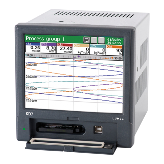
4. RECORDER CONSTRUCTION Alarms, binary inputs, Power analog outputs Housing pack Measuring systems LED diode Mounting brackets to fix screen the recorder in Door with lock the panel (access to CF card and USB) 4.1. LCD screen with touch screen For the visualization of measuring data and the configuration of recorder parameters, an LCD TFT 5,7”... -
Page 10: Compactflash Memory Card, Usb Interface, Led Diode
4.2. CompactFlash memory card, USB interface, LED diode A CompactFlash card with capacity up to 4 GB is foreseen for the measuring data storage in the KD7 recorder. It is recommended to apply CF cards produced by SanDisk company, in the recorder. - Page 11 USB bus operates correctly without amplification at the distance up to 5 m). In order that the KD7 recorder was seen in a PC with MS Windows operating system and serviced through USB, one must install drivers and the KD Connect program from the delivered CDR being in the recorder accessories (for description and program installation (see section 9.1 ) .
-
Page 12: Terminal Plate
4.3 Terminal plate Programmable, universal and/or standard measuring channels Alarms, binary inputs, Analog outputs Link for Suplly a.c.or d.c current range (AI 1) 2 auxiliary packs Temperature sensor Link for current range (AI 6) Ethernet 10 BASE-T Interface measuring input Interface RS485 (2) or RS232... -
Page 13: Connection Of Analog Signals
Symbol of terminal Terminal description group 1 and 2 Connecting sockets of measuring packages (AI 1..12 ) - 6 or 12 standard measuring inputs - 3, 6 or 12 measuring programmable inputs. Connecting sockets for alarm packages ( AL 1..32 ) 3 and 4 (8 or 16 electromechanical relays REL and 8 or 16 semiconductor OptoMos relays) -
Page 14: Analog Output Systems Ao 1
Two-wire connection: - Resistance thermometer RTD - Resistance transmitter Note: the balancing resistance R should have a resistance equal to the total resistance of both connecting wires of RTD and transmitter with terminals Three-wire connection: - Resistance thermometer RTD - Resistance transmitter - Potentiometric transmitter Note: wires connecting RTD with terminals 2 and 3 should have the same resistance... -
Page 15: Connection Of Digital Signals
4.3.2 Connection of digital signals 4.3.2.1 Alarm systems AL 1..32 and binary inputs BI 1..16 - Connection to terminals of the alarm system with semiconductor relays: AL1..16 (OptoMOS) and to terminals of the alarm system with electromechanical relays AL1..16 (REL.) Input parameters for the alarm system with electromechanical (REL.) and semiconductor relays (OptoMOS) are given in the section 10 “Technical data”. -
Page 16: Interfaces Rs485(1), Rs485(2), Rs232, Ethernet 10-Base-T
To connect the recorder with the hub (concentrator) or the switch, one must use a cable with leads 1:1 acc. to the description as on the drawing above. To a direct KD7 recorder connection with the PC, one must use a crossover cable: Tx +... -
Page 17: Recorder Supply (Ac Or Dc)
4.3.3 Recorder supply (AC or DC) Caution: The recorder must be earthed or zeroed. 5. GRAPHICAL SIGNS ON THE RECORDER SCREEN 5.1 Status bar The CF card in the recorder is partially filled Information about the opening possibility of the Context Menu, by the screen pressure in Alarm in the recorder any place. -
Page 18: Service Menu
5.3.Service menu Selection approval, introduction of changes. Cancellation without introduction of changes Buttons for global navigation Buttons for navigation on accessible options Buttons for global copying of settings between menu windows Introduction of a number or a character string. Option selection from the list or the dialogue Context help 5.4. -
Page 19: Dialogues
5.5.Dialogues - Selection: Single: Multiple: - Introduction of numbers - Introduction of a character string (small and capital letters, numbers and special characters, password) Small and capital letters Numbers and special characters: Password (replaced by dots) : 6. STARTING THE RECORDER After connecting the supply, the start screen with the producer’s logo. -
Page 20: Context Menu
Menu is displayed. Disabling of the context In the standard option, the basic set of functions necessary for the current service of the KD7 recorder is accessible in the menu. Selection for the edition of the next group from programmed 1...4 measuring groups on the screen. - Page 21 Opening of the KD7 Control Panel window with programming options of the recorder KD7 parameters. - transition to the configuration of recorder parameters in the “KD7 Control Panel” window, see section 6.2. The contents of the Context Menu can be extended (see p. 7.9) by extra options: transition into the archive mode (concerns the time and linear diagram, 2D), screen image shot on the CF card (in the format: *.bmp) ,...
-
Page 22: Entry Into The Recorder Parameter Configuration, "Kd7 Control Panel" Window
6.2. Entry into the recorder parameter configuration, “KD7 Control Panel” window In order to transit into the recorder configuration, one must select the KD7 Control Panel symbol in the Context Menu: Transition to the recorder configuration The window of the user’s selection appears, which will carry out the given configuration. -
Page 23: Configuring The Recorder
A renewed pressure of the button causes the return to the classical view. 7. CONFIGURING THE RECORDER The KD7 Control Panel is the window in which we obtain the direct access to the KD7 servicing menu: - general settings of the recorder, see section 7.1 - configuration of logic channels, see section 7.10... -
Page 24: General Settings
7.1 General settings After pressing the icon, the configuration of general parameters is coming open: recorder description, selection of the menu language, setting of the date and time, selection of the temperature unit, capacity of the event log (audits), time of screen blanking, setting of screen brightness. -
Page 25: Ethernet
Selection : - Disabled Disabled - Activate Math functions: - (activation procedure see section 7.10.3.3) 7.2 Ethernet pressing the icon, After the window of parameter configuration of the Ethernet interface is coming open. Programming menu of Ethernet interface parameters . Mark the selected function Enable DHCP Device IP... -
Page 26: Safety
Programming menu of Modbus Master and Modbus Slave interface parameters: Selection: ASCII 8N1, ASCII 7N2, ASCII 7N1, Mode: ASCII 7O1, RTU 8N2, RTU 8E1, RTU 8O1, RTU 8N2 RTU 8N1, Selection: 300, 600, 1200, 2400, 4800, 9600, 14400, Transmission: 19200, 28800, 38400, 56000, 57600, 28800 Master 115200, 128000, 256000... -
Page 27: System Information
Programming menu of access principles to KD7 configuration. Editing user: 1 (Admin), 2 (User 1)...8 (User 7) Selection: 1 (Admin) Enabled (access to all settings) User Selection: 2 (User 1)...8 (User 7) Enabled Disabled/ Enabled Name: Name edition User 1 Password: .. -
Page 28: Alarm And Analog Outputs
Free space on the CF card: 2,31MB (2364 KB) Total capacity of the CF card: 15,28 MB (15648 KB) State of internal buffer: Information about the number of free records and KD7 worktime to fill the buffer of each active measuring groups. Selection: File browser –... -
Page 29: Cf Card
Note: the alarm type, activation level and hysteresis are settled when configuring the given logic channel (Output icon), see section 8.5.2. Menu to program alarms and analog outputs: Selection: Selection of the alarm or analog output from the list of accessible outputs in the recorder. Selection: Disabled /Logic channel selection (1..32) / Choice of the... -
Page 30: Configuration, Visualization And Archiving Of The Channel Group
7.8. Configuration, visualization and archiving of the channel group After pressing the icon, the window of programming and visualization of 1...4 groups of channels is opening. One must define the group name, select 1..6 logic channels for the group and program visualization parameters and data archiving, (see section 8.2). -
Page 31: Context Menu
Selection: Arch. disabled by: Lack/Logic channel selection, the state of Events which influences the event Save data on CF: realization. Create new file: Edition Setting of the screen Auto-views delay: switching time in the given group Edition of parameter Events: value Lack, Lack Common... -
Page 32: Inputs (Logic Channels)
In the Customize context Menu window, one can mark selected functions for the context menu. The extended version of the context menu will be accessible after confirming the selection, exiting from the KD7 Control Panel, storage and setting the changed recorder configuration. 7.10 Inputs (logic channels) After pressing the icon, the programming window 1...32 logic channels... -
Page 33: Definition Of Logic Channel
7.10.1 Definition of the logic channel Logic channels are medium elements between inputs (see section 7.10) and outputs (see section 7.6 ) allowing to a flexible creation of connections between them. Analog inputs (AI 1..12), interface inputs (CI 1..24), mathematical functions (MT 1..16), binary inputs ( B1..16), logic channel alarms (A1,A2) and logic channel totalizers (1..32) are inputs for logic channels. - Page 34 Exemplary presentation of connections between logic channels, inputs and outputs: Possibilities resulting from the application of the intermediating element in the form of logic channels: • In successive logic channels, one can group inputs related with a defined process (independently on the kind of these inputs), what facilitates the configuration of outputs. •...
-
Page 35: Menu Of Logic Channel Programming
7.10.2 Menu of logic channel programming Logic channel Ch1 ... Ch32 / Copy to: copying of settings Selection : into the selected channel Selection: Disabled / Analog inputs, Modbus Master inputs, Mathem. functions, Binary AI1-Analog input ,0-10V inputs, Alarms as inputs. Input type: Menu of the selected input Configuration:... - Page 36 Selection: Alarm log: On/Off – storage of the alarm in the log file enabled Selection: Disabled, Integral, Counter Type: Integral Selection and edition: Unit, Totalizer disabled V, Lack, Lack Units and events through, Totalizer reset through Selection and edition: 0, Integral Decimal point, counting Totalizer 0.000000,...
-
Page 37: Selection And Configuration Of The Input For A Logic Channel
7.10.3 Selection and configuration of an input for a logic channel. In the selection menu and configuration of inputs, for the set logic channel, options to disable this channel are accessible or the selection and configuration of one of the accessible input. ▪... - Page 38 Programming menu of interface inputs (Modbus Master): Configuration CI1 - Modbus Master inputs Selection: State: Disabled/ enabled enabled Modbus device ID: Parameter edition General Edition of parameter values: Range: Min and Max of the range 0.0 – 100.0 Description: Description edition Register address: Parameter edition Selection:...
-
Page 39: Analog Input Ai 1
7.10.3.2 Analog input AI 1..16 a. Standard analog inputs AI 1 ... AI16: Configuration AI1 – Analog inputs 0…20mA Selection: Opening the menu General Range: 0.00 ... 20.mA of range programming Precision: Auto Edition of the Min: 5.00 parameter value Range Edition of the Max:... - Page 40 Choose the type of the output signal and set the input Signal. The value of the upper range limit (Max) must be higher than the value of the lower limit value (Min), preserving its minimal span acc. the table as above. Next, write the name and signal description in and set parameters of the output signal (Precision, Min, Max and unit.
- Page 41 After selecting the signal type, set the upper (Max) and lower (Min) limit of the input signal. The value of the upper range limit (Max) must be higher than the value of the lower limit value (Min), preserving its minimal span acc. the table as above. Cold junction compensation: Defines the way of the thermocouple cold junction - Internal (ACJC): Sets the self-acting cold...
- Page 42 The way of the Line Resistance parameter programming depends on the way of the sensor connection. - in a three-wire and two-wire connection with a balancing resistance, one must program the 0 Ω value. Each another value will be treated as the line resistance and taken into consideration when calculating the measurement, what causes the error uprising.
-
Page 43: Mathematical Functions Mt 1
KD7 Control Panel → General settings → Extensions menu: Enabled/disabled service of mathematical functions follows after the configuration storage. In the KD7 Control Panel → Inputs menu, the option to disable the selected logic channel or choice e-g , the mathematical function for this channel is accessible When mathematical functions are disabled (KD7 Control Panel →... - Page 44 Each from logic channels can be disabled. • Configuration menu of mathematical functions After entry into KD7 Control Panel → Inputs → Mathematical functions (MT1..16), one can start to the edition of the selected function:...
- Page 45 Output range of the logic channel. The data source for the configuration of mathematical functions are: Analog measuring inputs AI1..12, Binary inputs (BI1..16), Interface Modbus Master inputs (CI1..24), Alarms A1 and A2 in logic channels 1..32, Mathematical functions (MT1..16), Totalizers – integral or counter (TOTC1..32), Values of logic channels: Average (AVGC1..32), Minimal (MINC1..32) or Maximal (MAXC1..32) and functions, mathematic and logic operators (as below).
- Page 46 After the edition, write the description and the output function range. It should be determined at least in the area of its variability. Next, write the name and channel description in, and set output parameters of the logic channel ( for which the function is the signal source): description, output range of the logic channel, signal type, precision, unit.
- Page 47 Mathematical and logic functions: Function Description round(x) Returns the value x rounded to the nearest integer sin(x) Sine of number x Arc sine of number x asin(x) Hyperbolic sine of number x sinh(x) Cosine of number x cos(x) Arc cosine of number x acos(x) Hyperbolic cosine of number x cosh(x)
- Page 48 Mathematical and logic operators: Operator Function Description Addition x + y Subtraction x – y Multiplication x * y Division x / y x ^ y Raising to a power Negation of the number sign Modulo, returns the fractional part of the division x %y operation x/y >...
-
Page 49: Binary Input Bi 1
7.10.3.4. Binary input BI 1..16 For the logic channel as the input signal, one can select one of the accessible binary inputs BI 1..BI 16 The signal type of the output channel is set automatically as binary and will be visualized and archived in this form. -
Page 50: Alarm Of The Logic Channel 1
7.10.3.5. Alarm of the logic channel 1…32 For the given logic channel 1..32, one can choose as the input, one of two alarms from another logic channel. The type of output signal, for this channel, is set automatically as binary and it will be visualized and archived in this form (see section 8.2). -
Page 51: Configuration And Service Of Event Logs
For the chosen logic channel, one can select as the input, the totalizer (Counter or Integral) programmed in another logic channel. The programming of parameters in the Totalizer tab must be carried out acc. to the description as in section 8.5.3. ,, Totalizer programming (Counter / Integral)”. In the General tab one can write the name and description of the logic channel. -
Page 52: Review And Service Of Event Logs
Maximal capacity of the Statistic log is about 400 records. After exceeding this capacity, the log is overwritten. 7.11.1 Review and service of event logs After pressing the screen, during the visualization of measuring data, the Context menu is displayed. The pressure of the icon causes the view appearance of one of the event log and switching the successive views of other logs. -
Page 53: Programming Of Event Logs
7.11.2 Programming of event logs 1. Setting of the last records number to logs (Audit, Alarm and Statistics) shown on the recorder screen. 2. Setting in the Logic channel [1…32] the record of events to the alarm log (Enabled/Disabled). When selecting the record option: Disabled – messages will not appear in the log. When selecting the record option: Enabled –... - Page 54 - Select the Totalizer type (Integral or Counter) - After choosing the Unit and events menu in the open window Totalizer units and events select the option Enabled for the Record to the log menu. - The window Time setting of data storage to the Statistics log will be opening.
-
Page 55: Edition Of Operator Messages
4. Setting in the measuring group [1…4] the archive option of data from alarm and statistics logs. In the Arch. tag of the edited measuring group for the Alarm log and the Statistics log, and in the Common tag for the Audit log, one can set up the option of data archiving: Enabled –... - Page 56 During the recorder operation in the measuring and recording mode, in the option: Context menu - Operator’s messages – Choose the option – Own message , one can edit a message which is currently stored in the message log without the need to transit to the recorder configuration menu.
-
Page 57: Exit From The Recorder Configuration
( with proper names). Applying them, one can quickly adapt the recorder to current user’s needs. 3. One can also prepare configuration files in the PC computer through the KD7 Setup program (see section 9.2) -
Page 58: Selected Elements Of The Recorder Current Service
8. SELECTED ELEMENTS OF THE KD7 RECORDER CURRENT SERVICE 8.1 CompactFlash memory card For the data storage in the KD7 recorder, one can use CompactFlash memory cards with a capacity from 16 MB up to 4 GB. It is recommended to use CompactFlash cards from SanDisk ®... -
Page 59: Data Storage On The Cf Card (Card Storage Capacity)
During the recorder operation, when measuring data are stored in the recorder memory, the LED diode placed on the KD7 frontal panel, lights in green. When data from the recorder memory are reproduced on the CF card, the LED diode placed on the KD7 frontal plate changes the colour from green into red. - Page 60 Note: Using The Program KD Connect (see section 9.1) , one can copy data in the PC, from the inserted CF card in the recorder and its full clearing. During the recorder writer, data from each measuring group (see p. 8.2.1) are stored in the KD7 buffer.
-
Page 61: Visualization Of The Cf Card State On The Screen
8.1.5 Review and erasing of files from the CF card After selecting the o icon in the KD7 Control Panel window, names of files stored on the CF memory card are displayed in the Files Browser window. After selecting the given file and confirming the selection, this file is deleted from the CF card. -
Page 62: Removal/Replacement Of The Cf Card, Storage Of Archive Data
If the card is not inserted into the recorder or is not formatted, a message informing about its lack is displayed 8.1.6 Removal/replacement of the CF card, storage of archive data In order to take out safely the CF card from the recorder (without the loss of measuring data ), one must open the Context menu window, (by pressing the screen with a finger), press the icon of the option selection in it, and mark Remove CF card in the Select one option open window. -
Page 63: Programming Of Logic Channel Groups 1
1..4 measuring groups (each with 1 .. 6 channels) for which an individual set of parameters is settled. After selecting in the KD7 Control Panel window the icon , the window of channel group edition is open. -
Page 64: Programming Group Parameters
The analog output value of the logic channel higher than zero is interpreted in KD7 as a logic state (ON) of the given channel. - Create new files: Lack/New files with data of measuring groups will be created at the moment... - Page 65 Each from 4 channel groups can be disabled. Measuring data from particular groups are stored in the CF memory card of 8 MB capacity, in the format *.csv or binary ( see section 8.3.) The text file in format *.csv is serviced by the Excel program, and the binary file can be reviewed in the KD Archive program (see section 9.4).
-
Page 66: Digital View Of The Channel Group
Communication error – for logic channel with interface measuring input CI Signal of binary type Totalizer field (Integral, counter) The type and the alarm value, in the given logic channel, can be read out in the KD7 Control Panel, in the menu of the Input icon. -
Page 67: Linear Chart Of The Channel Group
To change the screen view from horizontal into vertical (concerns the linear screen and bargraph), one must choose the vertical chart orientation in the KD7 Control Panel – Visualization and archiving (see p. 8.2.1), in the Screen tab. - Page 68 Settings of the type and alarm value in the selected logic channel can be read out in the KD7 Control Panel channel, in the Output icon menu, Alarm tab. Totalizer data are not displayed on linear screens of the channel group.
-
Page 69: View Of The Channel Group In The Form Of Bargraphs
8.2.4 View of the channel group in the form of bargraphs - Vertical: Alarm state in the Alarm state in the channel channel Overflow of the Max range, alarm in the Alarm of Max type set Alarm of Max type set out channel beyond the upper range of the upper range limit. -
Page 70: Analog View Of The Channel Group
Index of the set alarm of Max type Alarm in the recorder Alarm in the channel Index of the alarm of Min/Max type set beyond the output range of the logic channel. Binary type of signal: 1 (ON) / 0 (OFF) 8.2.5 Analog view of the channel group Communication error. -
Page 71: Statistic View Of The Channel Group
The set area of the Max type alarm is marked in red color on the analog indicator. Overflow of Max range, alarm enabled in the channel Max alarm range Max alarm type enabled Overflow of Max range Dot indexes of measuring range overflow: Max (red) and Min (blue) Binary type of signal: 1 (ON) / 0 (OFF) 8.2.6 Statistic view of channel group... -
Page 72: Enabling/Disabling Of The Screen Automatic Switching In The Group
After programming in the edition group window, in the Common tab, the time of changing the screen views (the screen is common for all measuring groups), one can enable or disable during the visualization, the option of automatic screen switching without the necessity to enter into the KD7 Control Panel. -
Page 73: Zoom Scale Function Of The Signal (Measuring Magnifier)
Zoom scale (see section. 8.2.8). … KD7 Control Panel →Inputs: After programming the Zoom scale function , one can enable the display of the measurement result in limits of this parameter. -
Page 74: Selection Of The Measuring Data File Format (Digital Signature)
Output range of the 3 th logic channel The display switching of the measurement result of selected channels follows on the view in limits defined by the parameter Zoom scale (Logic channel (n) Visual) 3 th logic channel , Zoom scale is enabled To enable the Zoom scale function, one must in the option window of the Context menu, during the display of the linear screen, select again the function Zoom scale for signals and in the Select options window, disable marked previously channels (through tapping the screen by a finger... -
Page 75: Structure Of The Data Flow In Kd7 Recorder
The program shows the data area in which changes have been made. 8.4 Structure of the data flow in the KD7 recorder After selecting Input icons in the KD7 Control Panel window, the selection and programming the Logic channel window is accessible ( programming and explanation of the logic channel notion (see section 7.10) - Page 76 See sect. 8.2 See sect.. 8.1 Editing Group See sect. 8.2 1... 4 See sect. 7.10 Disabled / Input type: - Modbus Master Input: CI 1...24 Logic Channel - Analog Input: AI 1...12 Ch1...32 - Math. Function: MT 1...16 General - Binary Input: BI 1...16 Visual - Totalizer of the logic channel 1..32...
-
Page 77: Programming Logic Channel Parameters
8.5 Programming logic channel parameters After selecting the icon in the KD7 Control Panel window, the logic channel edition window is opening 8.5.1. Programming General, Visualization and Common parameters After selecting Input icon in the KD7 Control Panel window, select one of the accessible logic channels in the General tab for Configuration. - Page 78 In the General tab of the logic channel window, one must write the name and channel description and define its output range (input measuring data are proportionally converted into values in programmed limits of the output range and in output values are stored on the CF card, and displayed on the screen).
-
Page 79: Programming The Logic Channel Alarm
8.5.2 Programming of alarms in logic channels. In logic channels, choose and set alarm parameters in tags A1 and A2 (settings will be active after the write of the recorder configuration): • Alarm type: - Disabled or - Min, Max - alarm jest włączony gdy wartość kanału jest poniżej /powyżej/ ustawionej wartości alarmu - Range ON., Range OFF –... - Page 80 • Percentage (for type Percentage and Percentage Off) – edition of values in percentage of the channel range. • Hyst. value (for type Value and Value Off) – edition of values in channel range units (positive values) • Time (hysteresis value in time units) –...
- Page 81 Fig. 2 Functional diagram of the Value On alarm type. Fig. 3 Functional diagram of the MAX alarm type taking in consideration the hysteresis of Value and Time type • Alarm controls:...
- Page 82 - Confirm type: None – option disabled Latch – the alarm state is supported in the recorder till it will not be confirmed by the operator. Accept – switching off the alarm state in the recorder by the operator. During the recorder operation, one can choose in the context menu, the option of alarm confirmation acc.
-
Page 83: Programming Totalizer Parameters (Counter/Integral)
• storage in the log Disabled / Enabled – storage of alarm messages in alarmowych Alarm log. 8.5.3. Programming Totalizer parameters (Counter/Integral) Choose the type of programmed function in the Totalizer tab ( see section 8.3): Disabled, Integral or Counter ▪... - Page 84 Totalizer disabled by: select the logic channel which the logic state 1 (ON) disables the totalizer action (the state in the disabling moment will be preserved). Totalizer reset by: select the logic channel in which the change of the logic state from 0 (OFF) to 1 (ON) will cause the setting of the totalizer state on its value minimally programmed (see numeric settings) and the count restart.
- Page 85 • When choosing the type: Integral, one must set following groups of parameters: - Unit and events - Numeric settings - Time settings - Alarm settings In the window of parameters “Totalizer units and events” following parameters are programmed: Unit: select defined units or program the own unit. Record to the log: after selecting the “Enabled”...
-
Page 86: Programming Of Parameters: Common
In the window of parameters “Totalizer time settings” following parameters are programmed: Base time: 1 sec, 1 min, 1 hour, 1 day Time constrains: Continuous, Daily (24 hours), Daily (From – To), Weekly, Monthly Dayly time reset at hour: edition of the parameter Hour/min/sec, concerns the count type: Dayly (24 hours), Weekly, Monthly. -
Page 87: Totalizer Control (Counter/Integral)
8.5.5 Totalizer control (Counter/Integral) After the previously programming of the Totalizers function (Integral or Counter), one can control them choosing the Select options icon in the Context Menu Following control options of all active totalizers (Integral or Counter) are available: - Reset all/selected: Setting the state of all selected totalizers in logic channels on the level of programmed minimal values. -
Page 88: Programming Outputs
8.6. Programming outputs 8.6.1. Programming analog outputs After selecting the Outputs icon in KD7 Control Panel, the window for the signal source selection (of the Logic Channel 1...32) is opened for 1…8 analog outputs. Select the analog output (AO 1...8) from available outputs in the recorder, and assign the input signal source (Logic Channel 1..32) to it, in the General tab. - Page 89 8.6.2. Programming alarm outputs After selecting the Outputs icon in KD7 Control Panel, the window of the signal source selection (Logic channel 1...32 or Alarm of Logic Channel 1..32) for 1..16 alarm outputs. Select one from available alarm outputs (AL 1..32), assign to it in the General tab, the input signal source (Logic channel 1..32 or Alarm of Logic Channel 1..32).
-
Page 90: Edition Of Recorder Users
1 (ON) of the given channel. 8.7 Edition of recorder users After selecting the security icon in the KD7 Control Panel, one can set up parameters for individual recorder users in the Editing user window. -
Page 91: Review Of Archived Data
- selection of the time scale for the archive chart, - selection of visualized logic channels on the archive screen, - enabled/disabled Zoom scale parameter (set up in the menu: …KD7 Control Panel→Inputs – Logic channel 1..32→Visual →Zoom scale ) -
Page 92: Calibration Of The Touch Screen
8.9 Calibration of the touch screen After selecting the icon in the KD7 Control Panel window, on the LCD screen tab of the General settings window, the Touch screen calibration procedure is available. One must carry out the touch screen calibration in case of incorrect reaction occurrence when... -
Page 93: Updating Of The Recorder Software
The KD7 software is continually updated taking into consideration users’ opinions about the KD7 recorder, and as development works will be conducted in the company. New software versions, in the form of updated files will be available for users interested in KD7 on the page: http://www.lumel.com.pl After recopying the file on the CF memory card (e.g. -
Page 94: Service Of Data Stored On The Cf Card, Visualization
The KD Connect program (see section 9.1) is destined for the communication between the PC computer and the KD7 recorder by means of the USB interface. It enables to carry out following operations: 1) copying files from the CompactFlash card, directly from the recorder on the PC computer ( e.g. -
Page 95: Programs On Pc
• The appearance of dialogue windows highly depends on the system personalization (as e.g.: the size of systemic types. The result of work with the KD7 Setup program is the configuration file for a recorder of a defined hardware configuration (kind and number of cards, settlement of slots). -
Page 96: Installation Of The Kd Connect Program
After the correct driver installation (a restart of the system is not required) one can transit to the installation of the program delivered with the KD7 screen recorder. Select the catalogue with the KD Connect program on the annexed CD disk and start the KDConnect_install.exe program. - Page 97 3. Selection of the in-coming catalogue for the application (Note: the installation in the default catalogue indicated by the installator is recommended) 4. Selection of the group name for the Start menu 5. Possibility to insert shortcuts in different places of the desktop 6.
-
Page 98: Program Service
(through the USB interface) to the PC computer, informs about this message in the information window and blanked icons on the toolbar View on the main application window with the connected KD7 recorder to the PC. Toolbar Systemic information collected from the recorder... - Page 99 • Toolbar The application toolbar is situated on the upper part of the window and has the following appearance: This toolbar allows to a quick access to the most important program options. Explanations of symbols are given below. Call of the collection option of marked files from the recorder into the PC computer.
- Page 100 Program options allow to the change of application language settings. The selection of the language as Default means the application start in the language consistent with the language of the operating system if it is serviced by this program. In the contrary, the default language of the application is English.
- Page 101 or from the toolbar: The standard window for file selection will appear: After selecting, the data transmission begins. Note: The function is also serviced through the mechanism “Drag&Drop”. For this aim, one must drag the selected file, e.g. from the Explorer Windows on the area of the file lists of the KD Connect program.
-
Page 102: Example Of Using The Kd Connect Program
The goal is to show one of the method of data collecting from the CompactFlash card being in the recorder. To get all data from the KD7 recorder in the PC computer, one must carry out following steps: • Start the KD Connect program in the PC computer, which it was installed on, •... - Page 103 • One must select the Select all option from the program toolbar: Then, all elements will be marked on the file list as files to get: • Next one must select from the program toolbar the Get Files option Next one must select from the program toolbar the Get files option: •...
-
Page 104: Error Messages
One cannot upload data in the recorder 9.2 KD7 Setup program KD7 Setup is a program enabling to prepare a configuration file in the PC computer for the KD7 recorder. After recopying the configuration on the CF memory card, it can be used for reprogramming of settings in the given KD7 recorder. -
Page 105: Program Service
• The appearance of dialogue windows depends notably on the system personalization (e.g. the size of systemic character types) The result of work with the KD7 Setup program is the configuration file for the recorder with a defined hardware configuration (kinds and number of cards, settlement of slots). - Page 106 - On the PC computer side a. Start the KD7 Setup program, call the context menu (tap on the area of the recorder screen), and next press the input icon in order to configure the recorder. b. The logging dialogue appears. One must transit into the configuration dialogue.
-
Page 107: Kd Check Program
(to save the file in the CF card, one can use a standard commercial reader of memory card). On the KD7 recorder side a. On can get the saved configuration in KD7 from the CF card and open after transiting to the KD7 Control Panel – Configuration, option: Open configuration from file. -
Page 108: Kd Archive Program
9.5 Service of the WWW server The KD7 recorder renders accessible its own WWW server for the remote monitoring of measuring values and the device state. In particular, the recorder side allows to: • obtain information about the device (serial number, device number and others), •... -
Page 109: General View
9.5.1 General view Selection of channel group Current measuring values Language selection Frequency of the page updating 9.5.2 View of the window to browse data from the CF card Save archive data to CF card... -
Page 110: View Of The Window With Information About The Kd7 Recorder
(see section 11), the access to WWW page can be suitably secured. If the access to KD7 is authorized (for a current user, the access password is set for the KD7 configuration) and in Ethernet configuration options, the access is selected with the NTLM... -
Page 111: Symbols Of The Kd7 Recorder On The Web Page
The logging window appears, in which, one must give user’s data: 9.5.5 Symbols of the KD7 recorder on the web page Following marks are used by the recorder WWW page. Symbol Meaning Overflow of the upper range Overflow of the lower range... -
Page 112: Ftp Download Application
After sending an update file on the CF card the update progress appears. If system update finishes and device resets with success the main page will be displayed. 9.5.7 FTP Download Application The FTP Download is an application to automate a download process of data files from a device to PC. -
Page 113: Technical Data
10. TECHNICAL DATA ▪ Programmable measuring system: - number of measuring channels: 3, 6 or 12 > 10 MΩ (U, TC); =100 Ω (I) - input resistance - sampling rate 350 ms (for 1 measuring place) - measuring accuracy according to the table 1 - additional measuring error with the ≤... -
Page 114: Logic Inputs
Rated operating conditions and additional errors: Table 2 Influencing quantity or Value, range or Number Measurement influencing factor reference conditions of the range additional errors or type attenuation Ambient temperature 01...13 0...23...50°C 0.25 / 10°C 0.2 % × range Supply voltage 90...230...253 V 01...13 0.1 % ×... - Page 115 - load resistance < 500 Ω - isolation to the housing 500 V d.c. Voltage: 4 (or 8) galvanicaly isolated - output signal 0...5 V, 1..5V load resistance ≥ 250 Ω or 0...10 V, load resistance ≥ 500 Ω - additional error 0.2% - isolation to the housing 500 V d.c.
- Page 116 with a touch screen - external data carrier CompactFlash up to 4GB - internal RAM memory (buffer) 6 MB - built-in operators and functions arithmetical, logic, integral - working temperature 0...23...50ºC - related air humidity < 75% (without condensation) - supply voltage 90...230...253 Va.c.
-
Page 117: Order Codes
Softwares servicing the recorder from PC: KD Connect, KD Check KD Connect, KD Check, KD Archive, KD7 Setup Acceptance tests: without an extra quality inspection certificate with an extra quality inspection certificate according to user’s agreements 1) Write the range code from the item 2...6 as above: (slot 1) -
Page 118: Maintenance And Guarantee
5) A key for the activation of mathematical functions can be ordered separately 12. MAINTENANCE AND GUARANTEE The KD7 recorder does not require any periodical maintenance. In case of some incorrect operations: 1. After the dispatch date and within the period stated in the guarantee card One should return the instrument to the Manufacturer’s Quality Inspection Dept. - Page 119 ALL OUR INSTRUMENTS HAVE MARK . FOR MORE INFORMATION, PLEASE WRITE TO OR PHONE OUR EXPORT DEPARTMENT KD7-09G/1 Lubuskie Zakłady Aparatów Elektrycznych - LUMEL S.A. ul. Sulechowska 1 65-022 Zielona Góra – Poland Export Department: Tel.: (48-68) 32 95 1 00 (exchange) Tel.: (48-68) 329 53 02 or 53 04...
Need help?
Do you have a question about the KD7 and is the answer not in the manual?
Questions and answers