
Related Manuals for Texas Instruments MSP-EXP430G2


Summary of Contents for Texas Instruments MSP-EXP430G2
- Page 1 MSP-EXP430G2 LaunchPad Evaluation Kit User's Guide Literature Number: SLAU318F July 2010 – Revised January 2015...
-
Page 2: Table Of Contents
Getting Started With MSP-EXP430G2 LaunchPad ......................Getting Started ............Demo Application, Internal Temperature Measurement ............ Develop an Application With the MSP-EXP430G2 LaunchPad ....................Developing an Application ......... Program and Debug the Temperature Measurement Demo Application ..............Disconnect Emulator From Target With Jumper J3 ................ - Page 3 Code Composer Studio™ v4 in Debugging Mode ........MSP-EXP430G2 LaunchPad With Attached eZ430-RF2500 Target Board ....................... Device Pinout ............Schematics, MSP-EXP430G2 Emulator (1 of 2), Revision 1.4 ............Schematics, MSP-EXP430G2 Emulator (2 of 2), Revision 1.4 ............Schematics, MSP-EXP430G2 Target Socket, Revision 1.4 ............
-
Page 4: Msp-Exp430G2 Launchpad Overview
Preface: Read This First If You Need Assistance If you have any feedback or questions, support for the MSP430™ devices and the MSP-EXP430G2 is provided by the Texas Instruments Product Information Center (PIC) and the TI E2E Forum (http://e2e.ti.com/). Contact information for the PIC can be found on the TI web site at http://support.ti.com. -
Page 5: Features
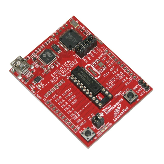
• High-quality 20-pin DIP socket for an easy plug-in or removal of the target device Figure 1. MSP-EXP430G2 LaunchPad Overview Kit Contents The MSP-EXP430G2 evaluation kit includes the following hardware: • LaunchPad emulator socket board (MSP-EXP430G2) • Mini USB-B cable, 0.5 m •... -
Page 6: Revisions
MSP430G2xx based application on the LaunchPad. Install the Hardware Connect the MSP-EXP430G2 LaunchPad socket board with the enclosed USB cable to a PC. The driver installation starts automatically. If prompted for software, allow Windows to install the software automatically. -
Page 7: Getting Started With Msp-Exp430G2 Launchpad
Getting Started With MSP-EXP430G2 LaunchPad Getting Started The first time the MSP-EXP430G2 LaunchPad Evaluation Kit is used, a demo application automatically starts as soon as the board is powered from the USB host. To start the demo, connect the MSP- EXP430G2 LaunchPad with the included mini USB cable to a free USB port. -
Page 8: Develop An Application With The Msp-Exp430G2 Launchpad
Section 2 offer support for the whole MSP430G2xx Value Line. The MSP-EXP430G2 LaunchPad needs only a connection to the USB of the Host PC—there is no external hardware required. The power supply and the Spy-Bi-Wire JTAG signals TEST and RST must be connected with jumper J3 to allow the onboard emulation connection to the device. -
Page 9: Disconnect Emulator From Target With Jumper J3
VCC must be opened, and a multi meter can used on the VCC Jumper to measure the current of the MSP-EXP430G2 target device and its peripherals. The jumper J5 VCC also must be opened if the LaunchPad board is powered with an external power supply over J6 Table 1 or the eZ430 interface J4. -
Page 10: Program Connected Ez430 Target Boards
TEST and RST of J3 must be open. The interface to the eZ430 target board is always connected to the MSP-EXP430G2 emulator, so the programming and debugging of a connected LaunchPad target device is possible only if the eZ430 target is not connected on the same time. The application UART, on the other hand, is connected directly to the LaunchPad target device, and jumper J3 can be closed to monitor the transmission from the LaunchPad target to the attached eZ430. -
Page 11: Connecting A Crystal Oscillator
Connecting a Crystal Oscillator The MSP-EXP430G2 LaunchPad offers a footprint for a variety of crystal oscillators. The XIN and XOUT signals of the LFXT1 oscillator can support low-frequency oscillators like a watch crystals of 32768 Hz or a standard crystal with a range defined in the associated data sheet. The signal lines XIN and XOUT can also be used as multipurpose I/Os or as a digital frequency input. - Page 12 Develop an Application With the MSP-EXP430G2 LaunchPad www.ti.com Table 3. Supported Devices (continued) Part Number Family Description 16-bit Ultra-Low-Power Microcontroller, 4KB Flash, 256B RAM, USI for SPI/I C, 16 Capacitive-Touch MSP430G2302 G2xx Enabled I/O Pins 16-bit Ultra-Low-Power Microcontroller, 8KB Flash, 256B RAM, USI for SPI/I...
-
Page 13: Msp-Exp430G2 On-Board Emulator
Develop an Application With the MSP-EXP430G2 LaunchPad www.ti.com MSP-EXP430G2 On-Board Emulator The MSP-EXP430G2 on-board emulator enables programming and debugging of supported MSP430 devices (see Section 4.7). It offers several features that are enabled by a 2-wire JTAG interface called Spy-Bi-Wire. For a more feature-complete emulator, the... -
Page 14: Schematics
MSP-EXP430G2 Hardware www.ti.com Schematics LED0 green Figure 6. Schematics, MSP-EXP430G2 Emulator (1 of 2), Revision 1.4 MSP-EXP430G2 LaunchPad Evaluation Kit SLAU318F – July 2010 – Revised January 2015 Submit Documentation Feedback Copyright © 2010–2015, Texas Instruments Incorporated... -
Page 15: Schematics, Msp-Exp430G2 Emulator (2 Of 2), Revision
MSP-EXP430G2 Hardware www.ti.com Figure 7. Schematics, MSP-EXP430G2 Emulator (2 of 2), Revision 1.4 SLAU318F – July 2010 – Revised January 2015 MSP-EXP430G2 LaunchPad Evaluation Kit Submit Documentation Feedback Copyright © 2010–2015, Texas Instruments Incorporated... -
Page 16: Schematics, Msp-Exp430G2 Target Socket, Revision
MSP-EXP430G2 Hardware www.ti.com QUARZ5 100nF 100nF Figure 8. Schematics, MSP-EXP430G2 Target Socket, Revision 1.4 MSP-EXP430G2 LaunchPad Evaluation Kit SLAU318F – July 2010 – Revised January 2015 Submit Documentation Feedback Copyright © 2010–2015, Texas Instruments Incorporated... -
Page 17: Schematics, Msp-Exp430G2 Emulator (1 Of 2), Revision
MSP-EXP430G2 Hardware www.ti.com LED0 green Figure 9. Schematics, MSP-EXP430G2 Emulator (1 of 2), Revision 1.5 SLAU318F – July 2010 – Revised January 2015 MSP-EXP430G2 LaunchPad Evaluation Kit Submit Documentation Feedback Copyright © 2010–2015, Texas Instruments Incorporated... -
Page 18: Schematics, Msp-Exp430G2 Emulator (2 Of 2), Revision
MSP-EXP430G2 Hardware www.ti.com Figure 10. Schematics, MSP-EXP430G2 Emulator (2 of 2), Revision 1.5 MSP-EXP430G2 LaunchPad Evaluation Kit SLAU318F – July 2010 – Revised January 2015 Submit Documentation Feedback Copyright © 2010–2015, Texas Instruments Incorporated... -
Page 19: Schematics, Msp-Exp430G2 Target Socket, Revision
MSP-EXP430G2 Hardware www.ti.com QUARZ5 100nF 100nF Figure 11. Schematics, MSP-EXP430G2 Target Socket, Revision 1.5 SLAU318F – July 2010 – Revised January 2015 MSP-EXP430G2 LaunchPad Evaluation Kit Submit Documentation Feedback Copyright © 2010–2015, Texas Instruments Incorporated... -
Page 20: Pcb Layout
MSP-EXP430G2 Hardware www.ti.com PCB Layout Figure 12. Layout, LaunchPad Top Layer MSP-EXP430G2 LaunchPad Evaluation Kit SLAU318F – July 2010 – Revised January 2015 Submit Documentation Feedback Copyright © 2010–2015, Texas Instruments Incorporated... -
Page 21: Layout, Launchpad Bottom Layer
MSP-EXP430G2 Hardware www.ti.com Figure 13. Layout, LaunchPad Bottom Layer SLAU318F – July 2010 – Revised January 2015 MSP-EXP430G2 LaunchPad Evaluation Kit Submit Documentation Feedback Copyright © 2010–2015, Texas Instruments Incorporated... -
Page 22: Layout, Launchpad Silkscreen
MSP-EXP430G2 Hardware www.ti.com Figure 14. Layout, LaunchPad Silkscreen MSP-EXP430G2 LaunchPad Evaluation Kit SLAU318F – July 2010 – Revised January 2015 Submit Documentation Feedback Copyright © 2010–2015, Texas Instruments Incorporated... -
Page 23: Bill Of Materials (Bom)
2X05 pin header male 6 pin header male 1.28mm 2x02 pin header male 3-pin header, male, TH S1, S2 Push button SLAU318F – July 2010 – Revised January 2015 MSP-EXP430G2 LaunchPad Evaluation Kit Submit Documentation Feedback Copyright © 2010–2015, Texas Instruments Incorporated... -
Page 24: Suggested Reading
See MSP-FET430 Flash Emulation Tool User's Guide (SLAU138) for details on using MSP430 USB FET and the Gang Programmer for a 2-wire Spy-Bi-Wire interface. Do not try to connect the standard JTAG connector to the MSP-EXP430G2 pinheads, as this could result in damage to the attached hardware. - Page 25 If you are experiencing difficulties in communicating to the attached MSP430 target device, even though all the communication drivers for the MSP-EXP430G2 are loaded correctly, the emulator is probably set to a wrong communication state. This can be fixed by reconnecting the LaunchPad evaluation kit and restarting the communicating application.
-
Page 26: Revision History
Corrected the description of jumper settings in the paragraph that starts "Jumpers 4 and 5 connect the UART ..........................interface..." NOTE: Page numbers for previous revisions may differ from page numbers in the current version. Revision History SLAU318F – July 2010 – Revised January 2015 Submit Documentation Feedback Copyright © 2010–2015, Texas Instruments Incorporated... - Page 27 IMPORTANT NOTICE Texas Instruments Incorporated and its subsidiaries (TI) reserve the right to make corrections, enhancements, improvements and other changes to its semiconductor products and services per JESD46, latest issue, and to discontinue any product or service per JESD48, latest issue.
- Page 28 Mouser Electronics Authorized Distributor Click to View Pricing, Inventory, Delivery & Lifecycle Information: Texas Instruments MSP-EXP430G2...
Need help?
Do you have a question about the MSP-EXP430G2 and is the answer not in the manual?
Questions and answers