Table of Contents
Advertisement
Quick Links
SERVICE AND
OPERATION
SEE
PAGE
i
FOR
LIMITED WARRANTY. AND LIMITATION OF LIABILITY.
4-INDENT DIE-LESS
DI ....
d D
wM
IIIIIIII-
DATE: 12/01
REVISION: C
COPYRIGHTC 2001
ALL RIGHTS RESERVED
MANUAL
IMPORTANT
INFORMATION
- - -,,- - - - - -i I::===\ �
00
0
0
0
Cl
HC134
CRIMP TOOL
DANIELS MANUFACTURING CORP.
ORLANDO, FLORIDA
CAGE 11851
-==
CONCERNING
DANIELS MANUFACTURING CORP.
526 THORPE
ROAD
ORLANDO, FL 32824
PHONE (407) 655-6161
FAX (40'7) 855-6884
WWW.DMCTOOLS.COM
E-MAIL: DMC@DMCTOOLS.COM
HC134-DB
Advertisement
Table of Contents

Related Manuals for DMC HC134


Summary of Contents for DMC HC134
- Page 1 SERVICE AND OPERATION MANUAL PAGE IMPORTANT INFORMATION CONCERNING LIMITED WARRANTY. AND LIMITATION OF LIABILITY. - - -,,- - - - - -i I::===\ � HC134 4-INDENT DIE-LESS CRIMP TOOL DI ..DANIELS MANUFACTURING CORP. ORLANDO, FLORIDA IIIIIIII- CAGE 11851 DATE: 12/01 DANIELS MANUFACTURING CORP.
- Page 2 180 days after delivery by DMC to the original purchaser. and written notice of any defect shall have been given to DMC within 30 days from the date such defect is first discovered. (c) Products for warrant y consideration shall be returned with all transportation charges prepaid to DMC.
-
Page 3: Table Of Contents
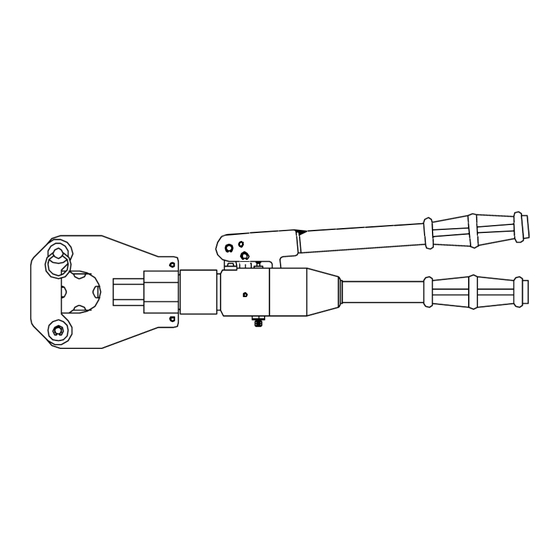
TABLE OF CONTENTS Warranty Inside Front Cover GENERAL OPERATION AND MAINTENANCE: Warning ..................... Cold Weather Note ................... Storage ..................... CAUTION: Crimping Small Diameter Splices and Terminals ....Preventative Maintenance Tool Requirements ......... Care of Hydraulic Tools ................Operating Instructions ................Conductor Preparation ................ - Page 4 BRIDGE LOCKING PIN HINGE PIN 4 INDENTERS (1 FIXED) (3 MOVABLE) RELEASE ROD GAUGE ADAPTOR � FITTING \--�� HANDLE RELEASE PIN PUMPING STROKE RETRACT MANUAL ADVANCE MANUAL RETRACT ROTATE AND DEPRESS HANDLE TO RETRACT INDENTERS ADVANCE HANDLE PUMP HANDLE RELEASE HANDLE FIGURE 1 1 OF 28...
-
Page 5: General Operation And Maintenance
These items can become lodged between the tool head and the indenter system (see Figure 4 ). GENERAL MAINTENANCE: The HC134 is a h y draulic crimp tool which requires well trained, experienced personnel having a clean work area equipped with adequate tools for major repairs, adjustments or maintenance. -
Page 6: Care Of Hydraulic Tools
CARE OF HYDRAULIC TOOLS This tool requires well trained, experienced personnel for major repairs, adjustm ents or maint enance . The following ru les for use in the field will prolong the time between major repair wo rk and help assure the dependability of the tool. 1. -
Page 7: Operating Instructions
OPERATING INSTR U CTION S CON DUCTOR PREPARATION : U s i n g a p ro p e r i n s u l a t i o n s t ri p p i n g too l , s t ri p t h e i n s u l a t io n fro m t h e co n d u cto r , b e i n g c a re f u l n ot t o n i c k t h e w i re stra n d s . -
Page 8: Removing A Spliced Cable
FIG U RE 3 WAR N ING Certai n s m a l l conn ectors w h e n not pro p e rly positio ned , ca n s e verely d a mage t h i s too l by becoming wedged b etween the indente rs a n d the tool hea d (see Figu re 4). -
Page 9: Preventative Maintenance
CHEC K THE SYSTEM P R E S S U R E : Check relief valve pressure setting using a DMC HPG-1 P ressure Gauge (see ADJU STING P U M P SYSTEM PRE SSU RE ) . - Page 10 l '� �1 ..y H P 1 036 H YDRAU LI C PU M P B- 1 244 115/32 X 1 .1 25 LC. SPRINC PIN 1 -1 079 1 /4-ZO X 1 Lil, 501ll<ET CN' 5CR. 4 - 1 058 E- RI N G ( 51 33-31 ) 1 -1 6 21 10-32.
-
Page 11: Tool Head Assembly
G REAS E FIG U RE 6 TO O L H EA D DISASS E M B LY : ( S E E FIG U R E 1 ) F u l ly ret ra c t t h e i n d e n t e rs by tu r n i n g th e a dva n c e h a n d l e c o u n te rc l ockwis e to t h e STO P po siti o n . - Page 12 FIGURE 7 HP1 036-22 SPRING RETAIN ER HEAD ADAPTOR HP1 0.36 - 1 9 H P1 0Jfi - 1 8 H P1 0Jfi - 1 2 PLUNGER ADVANCE HAN DLE HP1 0J6 - 9 HP1 03B - 4- COVER HP1 D36 - 1 PU MP BODY 8 - 1 1 B5 PLUN GER SPRING...
-
Page 13: Replacement Of Oil Plunger 0-Ring
CA UTION : THE OIL S U P P LIED I N EAC H KIT IS NOT FOR COLD WEATH E R O PERATIO N ( S [ E COLD W EAT H ER NOT E ) . D O NOT US[ BRA K [ rLUID! Rotate the ad vance han d le full y c ounte rclockwise to ret ract the i n dente rs and ret urn the oil to the oil chamber. -
Page 14: Inspection / Replacement Of Pressure Adjusting Valve
1:illIE. C over the open end of the oil cylinder with a cloth or p ap er towel! Slowly apply pressure to the relief rod (see Figure 1 ) to bleed any air out of the system. This procedure may have to be repeated several times to remove <l ll of the air that ma y be trapped in the sys tem . -
Page 15: Adjustment Of Pump System Pressure
ADJU STMENT OF PU MP SYSTEM PRESS URE: Adjusting t he system pressure req uires a DMC H PG1 Pressure Gau g e . Screw th e HPG - 1 Gaug e onto t he gauge ad a pter 4 5 lo cated o n t h e b ottom side of the pum p (see Figure 1 0 ) . -
Page 16: Removal Of Ram Lip Seal
RE MOVAL O F RA M LI P SEAL: (SEE FIG URE 7) CAUTIO N : REMOVAL OF RAM LIP SEAL S H O U LD N OT B E ROUTINELY U N DERTAKEN. THIS SEAL SHO U L D BE REMOVED ONLY AS A LAST RESORT. WHEN HANDLING THIS S EAL, PARTIC ULAR CAR E S H O U LD B E TAKE N TO PROTECT THE SEALING S U RFACE AND NOT TO DISTO RT T HE SPRING ENERGIZER... - Page 17 � ( � PO RT FAR SI D E (SEE N OTE PAG E 1 6) FIG U RE 1 2 1 - 1 657 3/8- 24 X 5/B H P1 036 - 1 5 PSI VALVE B-1 1 91 SP RI NG, PSI B-1 1 8B SPR IN G, OU TSI D E...
-
Page 18: Removal Of Ram Return Spring
.tillIE. Care should be taken to en sure that c rush was he r 1 9 is replaced ( see Figure 7). R E M OVAL OF' RA M R E T U R N S P RING: Follow ste ps for t he RE MOVAL O F RAM S EAL steps t hrou g h Grasp t h e top o f the spring 2 9 with an appropriate pair of pliers an d remove... -
Page 19: Removal Of Bypass Valve Ball
1 0. P ush re ta i n i n g rin g 1 7 do w n firm l y w ith a s u it a ble p i n pu n c h BY H AN D O N LY u ntil it b o ttom s out o n t h e s h o u l d e r . - Page 20 _ I _ I [ fr FIGURE 1 6 6- 1 258 1/4 X 1 - 1 /8 LG. SP R IN G PI N HP1 036- 5 STEEL BACKUP RI N G H ANDLE PI N H P 1 0J6- 21 H P 1 036-1 7 PI STON H P l 0.36- 1 3...
-
Page 21: Installation Of Pump Piston Seals
I NSTALLATI ON OF PUM P PISTON SEALS: Inspect pump piston cavity and piston for damage (see Figures 15 & 16 ). There should be no s c r a tche s , holes o r any su rface imperfect i o n s . Lubricate th e 0-ring 2 1 , tw o backup was h ers 2 2 and th e pump cavity bore wit h th e proper hydraulic oil . -
Page 22: Replacement Of Relief Rod Seal
R E P LACEM ENT OF RELIEF ROD SEAL (SEE FIGU RE 1 7) : Clean rel i ef rod 4 B a n d a pp ly a coa t i n g of hy dra ulic oil or grea s e t o the rin g g roove a rea of the ro d. -
Page 23: Replacement Of Gauge Adaptor Seals
I NS P ECTI O N OF RELIEF BALL VALVE : Before dis assemble, first remove advance handle coil s p ring following steps 1 through 5 of AD DITI ON OF HYDRAU LIC OIL. Loose n relief valve nut 42 until almos t out but DO N OT R [ MOVE ! (see Figure 1 6 ) . -
Page 24: Maintenance Tl Ps
MAI N T E N A N C E T l P S : G re a s e : M a g n a l u be®- G . M a g n a l u b e®- G i s a m u l t i p u rp o s e extre m e p re s s u re l u b ri c a n t c o nta i n i n g Tefl o n e, m a n u fa ctu re d b y : S a u n d e rs E nte rp ri ses , I n c . - Page 25 3 / 1 6 " DIA. 1 /4" DIA. ALL POSITI O N S ALL POSITI ONS U S I N G BALL 25 U S I N G BALL 2 6 (9/32" DIA. ) U S E ( 3/ 1 6" DIA . ) U S E 1 /4 "...
- Page 26 - � p � � SIDE PORT ON (SEE NOTE ..,E 1 6)
- Page 27 � 8-1 1811 !PRING, OUT 8-1 187 SPRING, INLE:T �I 15- 1 1 1115 SPRNO, HANlLE AETIJRN SPRINO , PUJNIER 15-1 1B!! SPRIN� R ... 11 RElURN 1 /4 X 1-1 /a LONG SPRING PIN 11-1 184 B-1 2=18 .3/11-24 X !I / II ADJ. S� 1 -1115"7 ( 2 } B-1 145...
- Page 28 6-1 03.2 6-1 1 39 "' 6-1 00J HC134-7B HC1J4-1 4 HC1 34-1 3 HC1 J4-1 2 HC134 - 1 1 HC1.34 - 1 0 PIN S PIN H INGE HC1 J4-9 HC1 34-8 PIN , LOCK HC1 J4-7A BUSHI NG...
-
Page 29: Troubleshooting, Diagnosis And Remedies
TROU B LES HOOTI NG, DIAGNOS IS A N D REM ED I ES TR O U B LE CAU S E O F TR O U B LE R E PAI R I N STR U CTI O N S 1 . - Page 30 TR OU BLE CAUSE OF TROU BL E REPAIR INSTRUCTIONS 4. Ba ll valve 2 6 o r bal l 4. If the hand le spring s back valve 2 5 lea king. a fter rea ching bottom of stroke when pumping, o ut let ba II valve 2 5 is leaking.
- Page 31 TROU B L E CAU S E OF TROU B L E REPAI R I N STRU CTIONS 5 . Oil l ea k a t release 1 . Fai l u re of relief rod sea l. 1 . � ol l ow recom mended p roce d u res va lve.
Need help?
Do you have a question about the HC134 and is the answer not in the manual?
Questions and answers