Lenovo ThinkStation P320 Hardware Maintenance Manual
Machine types: 30bj, 30bk, and 30bs
Hide thumbs
Also See for ThinkStation P320:
- User manual (84 pages) ,
- User manual (48 pages) ,
- User manual (140 pages)
Table of Contents
Advertisement
Quick Links
Advertisement
Table of Contents
Troubleshooting

Related Manuals for Lenovo ThinkStation P320


Summary of Contents for Lenovo ThinkStation P320
- Page 1 P320 Hardware Maintenance Manual Machine Types: 30BJ, 30BK, and 30BS...
- Page 2 1 “Read this first: Important safety information” on page 1 and Appendix G “Notices” on page 161. Second Edition (June 2017) © Copyright Lenovo 2017. LIMITED AND RESTRICTED RIGHTS NOTICE: If data or software is delivered pursuant to a General Services Administration “GSA”...
-
Page 3: Table Of Contents
(Windows 7 only) ..Enabling or disabling a device ..An introduction to Lenovo programs ..Enabling or disabling the automatic power-on of your computer . - Page 4 CD or DVD problems ... Lenovo Web site... . . 141 Intermittent problems ...
- Page 5 Appendix H. Trademarks ..163 © Copyright Lenovo 2017...
- Page 6 P320 Hardware Maintenance Manual...
-
Page 7: About This Manual
Use this manual along with the advanced diagnostic tests to troubleshoot problems effectively. Before servicing a ThinkStation computer, be sure to read and understand Chapter 1 “Read this first: Important safety information” on page 1. © Copyright Lenovo 2017... - Page 8 P320 Hardware Maintenance Manual...
-
Page 9: Chapter 1. Read This First: Important Safety Information
Do not use any power cords where the electrical contacts on either end show signs of corrosion or overheating or where the power cord appears to have been damaged in any way. © Copyright Lenovo 2017... - Page 10 P320 Hardware Maintenance Manual...
-
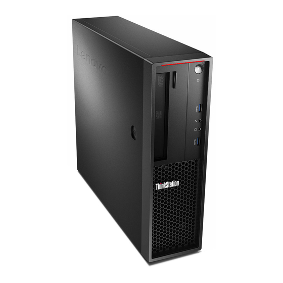
Page 11: Chapter 2. Product Overview
USB 3.0 connector Card reader (some models) Optical-drive eject/close button Press the button to eject or close the tray of the optical drive. Power indicator When the power indicator is on, the computer is turned on. Power button © Copyright Lenovo 2017... -
Page 12: Rear View
Press the power button to turn on your computer. If your computer is unresponsive, you can turn off the computer by pressing and holding the power button for four or more seconds. Storage drive activity indicator This indicator shows the status of the internal storage drives (such as hard disk drives or solid-state drives). On: The storage drives are active and data is being transferred. - Page 13 Figure 2. Rear panel Power-cord connector VGA connector ® Serial connector DisplayPort connectors (2) USB 3.0 connectors (4) USB 2.0 connectors (2) Microphone connector Audio line-out connector Audio line-in connector PCIe card area* Optional serial connector Ethernet connector Cable-lock slots (2) PS/2 keyboard and mouse connectors (some models) Security-lock slot Padlock loop...
- Page 14 Use this connector to attach an external modem, a serial printer, or other devices that use a 9-pin serial connector. DisplayPort connector (2) Use this connector to attach a high-performance monitor, a direct-drive monitor, or other compatible devices. USB 3.0 connectors (4) Use this connector to attach a USB-compatible device, such as a USB keyboard, mouse, storage drive, or printer.
-
Page 15: Computer Components
Use this connector to attach a Personal System/2 (PS/2) keyboard or a PS/2 mouse. Security-lock slot Attach a Kensington-style cable lock to the security-lock slot to secure your computer. For more information, see “Attaching a Kensington-style cable lock” on page 33. Padlock loop Connect a padlock to secure your computer. -
Page 16: Major Frus And Crus
Major FRUs and CRUs The following illustration shows the locations of the major FRUs and CRUs in the computer. To remove the computer cover, see “Preparing your computer and removing the computer cover” on page 69. Note: Depending on the model, some of the following components might not be available. P320 Hardware Maintenance Manual... - Page 17 Figure 4. Major FRUs and CRUs Chapter 2 Product overview...
- Page 18 The following table lists the major FRUs shown in Figure 4 “Major FRUs and CRUs” on page 9 and identifies which FRUs are also self-service CRUs or optional-service CRUs. Notes: • Self-service CRUs: Parts to be installed or replaced by customer themselves. •...
-
Page 19: Parts On The System Board
Number FRU description Self-service CRU Optional-service CRU Heat sink and fan assembly Lenovo factory recovery USB key Lenovo recovery disc set Miscellaneous parts kits Power cord Keyboard Mouse Parts on the system board Note: The system board might look slightly different from the illustrations. -
Page 20: Internal Storage Drives
4-pin SATA power connectors Thunderbolt™ connector Parallel connector eSATA connector SATA connectors Power fan connector USB hardware disable header Front bezel connector (for connecting LED indicators and the power button) Front USB 3.0 connector (for connecting USB USB 2.0 connectors (for connecting front USB 2.0 connectors on the front panel) connector, card reader connector, or Bluetooth connector) - Page 21 Figure 6. Drive bay locations Optical-drive bay Card-reader bay (available on some models) Primary hard-disk-drive bay Secondary hard-disk-drive bay PCIe card slots (4) Optical-drive bay The optical-drive bay supports the following devices. Depending on your computer model, one of them might be installed: •...
-
Page 22: Machine Type And Model Label
PCIe solid-state drives or other PCIe cards might be installed in the slots. Machine type and model label The machine type and model label identifies your computer. When you contact Lenovo for help, the machine type and model information helps support technicians to identify your computer and provide faster service. - Page 23 1. Depending on your Windows version, do one of the following: – For Windows 7: Click the Start button to open the Start menu. Right-click Computer, and then click Properties. – For Windows 10: Right-click the Start button to open the Start context menu. 2.
- Page 24 • Discrete audio card installed in one of the PCIe card slots (available on some models) (the connectors vary by audio card) Input/Output (I/O) features • 100/1000 Mbps Ethernet connector • Audio connectors (audio line-in connector, audio line-out connector, microphone connector, and headphone connector) •...
- Page 25 ® • Intel Standard Manageability (ISM) Intel Standard Manageability builds certain functionalities into computer hardware and firmware. Therefore, computers are less expensive for businesses and easier to monitor, maintain, update, upgrade, and repair. • Intel Active Management Technology (Intel AMT) With specific Intel platform capabilities and third-party management and security applications, Intel Active Management Technology enables IT administrators or managed service providers to easily and remotely discover, repair, and protect their networked computing assets.
-
Page 26: Computer Specifications
Accessing a program on your computer Note: For Windows 7, depending on your computer model, some of the Lenovo programs might be ready to be installed, so you must install them manually. Then, you can access and use these programs. -
Page 27: Installing A Program That Is Ready To Be Installed (Windows 7 Only)
An introduction to Lenovo programs This section provides information about the major Lenovo programs available on your operating system. Note: Depending on your computer model, some of the following programs might not be available. - Page 28 Category, click Hardware and Sound ➙ Devices and Printers, and then double-click the device with your computer name. Lenovo ID The Lenovo ID program enables you to create and manage your Lenovo ID. With a Lenovo ID, you can connect to everything Lenovo through a single (Windows 10) account.
-
Page 29: Chapter 3. Using Your Computer
When you register your computer with Lenovo, you enter required information into a Lenovo database. The information enables Lenovo to contact you when there is a recall or other severe problem and provide quicker service when you call Lenovo for help. In addition, some locations offer extended privileges and services to registered users. -
Page 30: Playing And Removing A Disc
• To remove dust or fingerprints, wipe the disc with a clean, soft cloth from the center to the outside. Wiping the disc in a circular direction might cause loss of data. • Do not write or stick paper on the disc. •... -
Page 31: Connecting To A Network
2. Open Windows Media Player. See “Accessing a program on your computer” on page 18. 3. Follow the instructions on the screen. • Burn a disc from an ISO file. 1. Insert a recordable disc into the optical drive that supports recording. 2. - Page 32 To connect to a Bluetooth-enabled device, do the following: 1. Turn on the Bluetooth feature of your computer. Ensure that the Bluetooth-enabled device is located within a distance of about 10 m (32.8 ft) from your computer. 2. Click the Bluetooth icon in the Windows notification area on the taskbar. Then, click Add a Device and follow the instructions on the screen.
-
Page 33: Chapter 4. You And Your Computer
• Length of the cables that are connected to other devices Comfort Although no single working position is ideal for everyone, here are a few guidelines to help you find a position that suits you best. The following figure sets an example for your reference. © Copyright Lenovo 2017... -
Page 34: Accessibility Information
Accessibility information Lenovo is committed to providing users who have hearing, vision, and mobility limitations with greater access to information and technology. This section provides information about the ways these users can get the most out of their computer experience. You also can get the most up-to-date accessibility information from the following Web site: http://www.lenovo.com/accessibility... - Page 35 • For Windows 10: Click Settings ➙ Ease of Access. 3. Choose the appropriate tool by following the instructions on the screen. Ease of Access Center mainly includes the following tools: • Magnifier Magnifier is a useful utility that enlarges the entire screen or part of the screen so that you can see the items better.
- Page 36 http://www.nvaccess.org/ Screen resolution You can make the text and images on your screen easier to read by adjusting the screen resolution of your computer. To adjust the screen resolution, do the following: 1. Right-click a blank area on the desktop. 2.
-
Page 37: Cleaning Your Computer
Then, you can type a message on your computer and send it to the telephone. Documentation in accessible formats Lenovo provides electronic documentation in accessible formats, such as properly tagged PDF files or HyperText Markup Language (HTML) files. Lenovo electronic documentation is developed to ensure that visually impaired users can read the documentation through a screen reader. -
Page 38: Keeping Your Computer Current
The cause of a problem might be change in hardware, change in software, or any other actions that might have taken place. A log book can help you or a Lenovo technician determines the cause of a problem. • Create Product Recovery discs. -
Page 39: Moving Your Computer
3. Follow the instructions on the screen. Note: The device drivers provided by Windows Update might not be tested by Lenovo. It is recommended that you get device drivers by using Lenovo programs or from the Lenovo Web site at http://www.lenovo.com/... - Page 40 P320 Hardware Maintenance Manual...
-
Page 41: Chapter 5. Security
The cable lock also locks the buttons used to open the computer cover. This is the same type of lock used with many notebook computers. You can order such a cable lock directly from Lenovo by searching for Kensington at: http://www.lenovo.com/support... -
Page 42: Attaching A Cable Lock
Figure 9. Kensington-style cable lock Attaching a cable lock A cable lock can be used to secure devices, such as the keyboard and the mouse, by locking the device cables to your computer. The cable lock attaches to the cable-lock slots on the rear of your computer. To attach a cable lock, do the following: 1. -
Page 43: Viewing And Changing Security Settings In The Setup Utility Program
Figure 10. Cable lock Viewing and changing security settings in the Setup Utility program To view and change security settings in the Setup Utility program, do the following: 1. Start the Setup Utility program. See “Starting the Setup Utility program” on page 39. 2. -
Page 44: Using Fingerprint Authentication
• For Windows 7: Use the Fingerprint Manager Pro or ThinkVantage Fingerprint Software program provided by Lenovo. To open the program, see “Accessing a program on your computer” on page 18. For more information about using the program, refer to the help system of the program. -
Page 45: Protecting Data Against Viruses
Your computer is preinstalled with an antivirus program to help you guard against, detect, and eliminate viruses. Lenovo provides a full version of antivirus software on your computer with a free 30-day subscription. After 30 days, you must renew the license to continue receiving the antivirus software updates. - Page 46 P320 Hardware Maintenance Manual...
-
Page 47: Chapter 6. Advanced Configuration
Then, select Yes in the window displayed, and press Enter. Enabling or disabling the automatic power-on of your computer The Automatic Power On item in the Setup Utility program provides various options for you to make your computer start up automatically. © Copyright Lenovo 2017... -
Page 48: Enabling Or Disabling The Erp Lps Compliance Mode
Then, select Yes in the window displayed, and press Enter. Enabling or disabling the ErP LPS compliance mode Lenovo computers meet the eco-design requirements of the ErP Lot 3 regulation. For more information, go http://www.lenovo.com/ecodeclaration You can enable the ErP LPS compliance mode in the Setup Utility program to reduce the consumption of electricity when your computer is off or in sleep mode. -
Page 49: Enabling Or Disabling The System To Record Thermal Alert Logs
1. Start the Setup Utility program. 2. Select Power ➙ Intelligent Cooling Engine (ICE) and press Enter. 3. Select ICE Performance Mode and press Enter. 4. Select Better Acoustic Performance or Better Thermal Performance as desired and press Enter. 5. To save settings and exit the Setup Utility program, press F10 or Fn+F10 (depending on the keyboard settings). -
Page 50: Using Bios Passwords
4. Select Yes in the window displayed and press Enter to confirm your selection. 5. To save settings and exit the Setup Utility program, press F10 or Fn+F10 (depending on the keyboard settings). Then, select Yes in the window displayed, and press Enter. Using BIOS passwords By using the Setup Utility program, you can set passwords to prevent unauthorized access to your computer and data. -
Page 51: Selecting A Startup Device
Setting, changing, or deleting a password To set, change, or delete a password, do the following: 1. Start the Setup Utility program. 2. Select Security. 3. Depending on the password type, select Set Power-On Password, Set Administrator Password, or Hard Disk Password and press Enter. 4. -
Page 52: Selecting A Temporary Startup Device
To update the BIOS, do the following: 1. Go to http://www.lenovo.com/support 2. To update the BIOS from your operating system, download the flash BIOS update driver according to your operating system version. To update the BIOS from a flash update disc, download the ISO image version (used to create a flash update disc). -
Page 53: Bios Level
• To determine the currently installed BIOS level, start the Setup Utility program and view the BIOS Revision Level on the Main page. • Sources for obtaining the latest BIOS level available – Lenovo support Web site: http://www.lenovo.com/support – Lenovo Customer Support Center –... -
Page 54: Configuring The System Bios To Enable Sata Raid Functionality
• RAID Level 0 – Striped disk array – Two hard disk drives minimum – Better performance without fault tolerance • RAID Level 1 – Mirrored disk array – Two hard disk drives minimum – Improved read performance and 100% redundancy To install a secondary hard disk drive, refer to “Secondary hard disk drive”... -
Page 55: Resetting Disks To Non-Raid
5. After deleting a RAID volume, you can: • Return to step 2 to delete additional RAID volumes. • See “Creating RAID volumes” on page 46 for RAID volume creation. • Use the up and down arrow keys to select Exit and press Enter. Resetting disks to non-RAID To reset your hard disk drives to non-RAID, do the following: 1. - Page 56 P320 Hardware Maintenance Manual...
-
Page 57: Chapter 7. Troubleshooting, Diagnostics, And Recovery
4. Run the diagnostic program. If the diagnostic program does not resolve your problem, continue with the next step. 5. Recover your operating system. 6. If none of these actions solve your problem, contact the Lenovo Customer Support Center. For a list of Lenovo Support phone numbers, go to http://www.lenovo.com/support/phone Service checkout and symptom-to-FRU index This chapter provides information about general service checkout and symptom-to-FRU index. -
Page 58: Problem Determination Tips
4. Turn on all external devices. 5. Turn on the computer. • Look for displayed error codes. • Listen for beep codes. • Look for readable instructions or a main menu on the display. If you did not receive the correct response, proceed to step 6 on page 50. If you do receive the correct response, proceed to step 7 on page 50. -
Page 59: Symptom-To-Fru Index
6. Have the same Diagnostic Diskettes (version) 7. Have the same configuration options set in the system 8. Have the same setup for the operating system control files Comparing the configuration and software set-up between “working and non-working” systems will often lead to problem resolution. -
Page 60: Beep Symptoms
Check/Verify FRU/Action Check the following for proper installation. Reseat connectors • Power cord • On/Off switch connector • On/Off switch power supply connector • System board power supply connectors • Microprocessor connection Check the power cord for continuity. Power cord Power-on switch Check the power-on switch for continuity. - Page 61 If the POST detects a problem, an error message appears on the screen. A single problem might cause several error messages to appear. When you correct the cause of the first error message, the other error messages probably will not appear on the screen the next time. POST error message Description/Action Error code...
-
Page 62: Miscellaneous Error Conditions
8998 Not enough shadow RAM resources This error message is displayed for OPTION ROM, not all devices when the shadow RAM resources initialized. Suggest to remove some for option ROM are insufficient. add-on cards, or change to UEFI If the legacy option ROM is mode in BIOS setup. - Page 63 Message/Symptom FRU/Action Diskette drive in-use light remains on or does not light 1. Diskette Drive when drive is active. 2. System Board 3. Diskette Drive Cable Blank screen except for flashing cursor. 1. System Board 2. Primary Hard Disk Drive 3.
-
Page 64: Undetermined Problems
Message/Symptom FRU/Action RPL computer does not RPL from server 1. Check the startup sequence. 2. Check the network adapter LED status. Serial or parallel connector device failure (system board 1. External Device Self-Test OK? connector) 2. External Device 3. Cable 4. -
Page 65: Startup Problems
Startup problems The computer does not start up when you press the power button. Solutions: Ensure that: • The power cord is correctly connected to the rear of the computer and to a working electrical outlet. • If your computer has a secondary power switch on the rear of the computer, ensure that it is switched on. •... -
Page 66: Cd Or Dvd Problems
The sound comes from one of the external speakers. Solutions: • Ensure that the speaker cable is inserted completely into the connector on the computer. • Depending on your Windows version, do one of the following: – For Windows 7: Click the volume icon in the Windows notification area on the taskbar. Then, click the speaker icon on top of the volume control. -
Page 67: Intermittent Problems
• Check the disc or package for regional coding. You might need to purchase a disc with coding for the region where you are using your computer. No audio or only an intermittent audio comes out while a DVD movie is playing. Solutions: •... -
Page 68: Ethernet Lan Problems
• Ensure that the computer starts up from the correct storage drive. Set the storage drive, on which the operating system resides, as the first startup device in the Setup Utility program. Note: In rare cases, the storage drive with the operating system might get corrupted or damaged. If this problem occurs, replace the storage drive. -
Page 69: Wireless Lan Problem
Wireless LAN problem Note: The wireless LAN feature is available only on some models. The wireless LAN feature does not work. Solutions: • Enable the wireless LAN feature in the Setup Utility program. Refer to “Using the Setup Utility program” on page 39. -
Page 70: Performance Problems
• Update or reinstall the Bluetooth driver. See “Keeping your computer current” on page 30. No sound comes from the Bluetooth headset or headphones. Solution: Set the Bluetooth headset or headphones as the default device. 1. Exit the application that uses the sound device (for example, Windows Media Player). 2. -
Page 71: Serial Connector Problem
• Right-click a blank area on the taskbar and open Task Manager. Then, end some tasks you are not performing. • Install additional memory modules. To purchase memory modules, go to: http://www.lenovo.com Serial connector problem USB device problems A USB device cannot be accessed. -
Page 72: Software And Driver Problems
• If you are unable to isolate and repair the problem yourself after running Lenovo Solution Center, save and print the log files created by the program. You need the log files when you speak to a Lenovo technical support representative. -
Page 73: Uefi Diagnostic Program
Note: If you are unable to isolate and repair the problem yourself after running Lenovo Companion, save and print the log files created by the program. You need the log files when you speak to a Lenovo technical support representative. -
Page 74: Recovery Information
1. Select the recovery medium as the startup device. 2. Follow the instructions on the screen to choose the appropriate recovery solution. • Use the recovery disc set provided by Lenovo to restore the entire storage drive to the factory-default settings. - Page 75 – Select the recovery medium you created earlier with the Windows tool as the startup device. Then, follow the instructions on the screen to choose the appropriate recovery solution. • Use the recovery USB key provided by Lenovo to restore the entire storage drive to the factory-default settings.
- Page 76 P320 Hardware Maintenance Manual...
-
Page 77: Chapter 8. Hardware Removal And Installation
2. Unlock any locking device that secures the computer cover. See “Locking your computer” on page 33. 3. Remove the two screws that secure the computer cover. 4. Press the cover-release button on the side of the computer and slide the cover to the rear of the computer to remove the cover. © Copyright Lenovo 2017... -
Page 78: Installing Or Replacing Hardware
• When installing or replacing an option, use the appropriate instructions in this section along with the instructions that come with the option. • In most areas of the world, Lenovo requires the return of the defective CRU. Information about this will come with the CRU or will come a few days after the CRU arrives. -
Page 79: Pcie Card
2. Release the three plastic tabs on the top of the front bezel and pivot the front bezel outward to remove it from the computer. Figure 12. Removing the front bezel 3. To reinstall the front bezel, first align the three plastic tabs on the bottom of the front bezel with the corresponding holes in the chassis. - Page 80 Your computer has two PCIe x1 card slots, one PCIe x4 card slot (negotiable link width x4, x1), and one PCIe x16 graphics card slot. To install or replace a PCIe card, do the following: 1. Prepare your computer. See “Preparing your computer and removing the computer cover” on page 69. 2.
-
Page 81: M.2 Solid-State Drive
Figure 16. Installing a PCIe card Note: If you are installing a PCIe x16 graphics card, ensure that the memory-slot retaining clips are closed before you install the card to avoid any interference during the installation. What to do next: •... - Page 82 b. The heat sink is secured by two mounting studs. Pinch the clips of the studs inward and push the studs upward to release the heat sink. Then, lift the heat sink off the M.2 solid-state drive adapter Figure 17. Removing the heat sink from the M.2 solid-state drive adapter c.
- Page 83 Figure 19. Installing the thermal pad 5. Insert the new M.2 solid-state drive into the M.2 slot. Then, insert the plug of the retention latch into the hole to secure the new drive. Figure 20. Installing the M.2 solid-state drive 6.
-
Page 84: Coin-Cell Battery
Figure 21. Installing the heat sink 7. Install the M.2 solid-state drive adapter into the appropriate PCIe card slot on the system board. See “PCIe card” on page 71. Note: It is recommended that you install the M.2 solid-state drive adapter into the PCIe x4 card slot. See “Parts on the system board”... -
Page 85: Memory Module
Figure 22. Removing the old coin-cell battery 4. Install a new coin-cell battery. Figure 23. Installing a new coin-cell battery 5. Reinstall the computer cover and connect the cables. See “Completing the parts replacement” on page 139. Note: When the computer is turned on for the first time after replacing the coin-cell battery, an error message might be displayed. - Page 86 Figure 24. Memory module installation order To install or replace a memory module, do the following: 1. Prepare your computer. See “Preparing your computer and removing the computer cover” on page 69. 2. Lay the computer on its side for easier access to the system board. 3.
- Page 87 Figure 25. Removing a memory module • If you are installing a memory module, open the retaining clips of the memory slot into which you want to install the memory module. Figure 26. Opening the retaining clips 6. Position the new memory module over the memory slot. Ensure that the notch on the memory module is aligned with the key in the slot.
-
Page 88: Optical Drive
Figure 27. Installing a memory module 7. Reinstall the PCIe x16 graphics card if you have removed it. What to do next: • To work with another piece of hardware, go to the appropriate section. • To complete the installation or replacement, go to “Completing the parts replacement” on page 139. Optical drive Attention: Do not open your computer or attempt any repair before reading and understanding the Chapter 1 “Read this first: Important safety information”... - Page 89 Figure 28. Pivoting the drive bay assembly upward 4. Depending on whether you are installing or replacing an optical drive, do one of the following: • If you are installing a new optical drive, do the following: a. Remove the metal static shield from the bay. b.
- Page 90 Figure 29. Removing the optical drive 5. Install the optical-drive retainer on the side of the new optical drive. Figure 30. Installing the optical-drive retainer 6. Slide the new optical drive into the drive bay until the optical drive snaps into position. P320 Hardware Maintenance Manual...
-
Page 91: Hard Disk Drive In The Front-Access Storage Enclosure
Figure 31. Installing the optical drive 7. Connect any required cables. For the optical drive, connect the power cable and the signal cable to the rear of the optical drive. What to do next: • To work with another piece of hardware, go to the appropriate section. •... - Page 92 2. Unlock the enclosure cover with the provided key as shown. Press the notch to open the enclosure cover. Figure 32. Opening the front-access storage enclosure cover 3. Press the pit on the bracket cover, and then grasp the tilted cover to pull the bracket out of the front- access storage enclosure.
- Page 93 Figure 35. Installing the 3.5-inch storage drive into the bracket 6. Slide the bracket with the new 3.5-inch storage drive into the front-access storage enclosure until it snaps into position. Press the notch to secure the enclosure cover and lock the enclosure cover with the key.
- Page 94 Figure 37. Opening the front-access storage enclosure cover 3. Press the pit on the bracket cover, and then grasp the tilted cover to pull the bracket out of the front- access storage enclosure. Figure 38. Removing the bracket from the front-access storage enclosure 4.
- Page 95 Figure 40. Removing the metal bracket from the plastic frame of the converter c. Carefully flex both sides of the metal bracket to remove the storage drive from the bracket. Figure 41. Removing the storage drive from the metal bracket 5.
- Page 96 Figure 43. Inserting the metal bracket into the plastic frame of the converter c. Push the metal bracket down until the tab is slightly curved. Then, push the bracket with the storage drive forward as shown until the tab snaps into position. Figure 44.
-
Page 97: Device In The Multi-Drive Conversion Kit
Figure 45. Installing the converter with the 2.5-inch storage drive into the plastic bracket 6. Slide the plastic bracket with the new 2.5-inch storage drive into the front-access storage enclosure until it snaps into position. Press the notch to secure the enclosure cover and lock the enclosure cover with the key. - Page 98 Note: The instructions on how to install or replace a slim optical drive in the kit also applies to the Slim Optical Drive Adapter. 1. Slide the kit out of the chassis. See “Optical drive” on page 80. 2. If you are replacing an old slim optical drive, do the following: a.
- Page 99 Figure 49. Installing the bracket to the new slim optical drive 4. Insert the new slim optical drive into the kit until you hear a click. The slim optical drive is secured in place. Figure 50. Installing the slim optical drive into the kit 3.5-inch internal storage drive To install or replace a 3.5-inch internal storage drive in the kit, do the following: 1.
- Page 100 Figure 51. Opening the kit from the rear 3. If you are replacing an old 3.5-inch internal storage drive, do the following: a. Press both clips simultaneously toward each other and slide the 3.5-inch internal storage drive out of the rear of the kit. Figure 52.
- Page 101 Figure 53. Flexing both sides of the bracket to remove the 3.5-inch internal storage drive 4. Flex the bracket and align pins , and on the bracket with the corresponding holes in the new 3.5-inch internal storage drive. Then install a new 3.5-inch internal storage drive into the bracket. Do not touch the circuit board on the internal storage drive.
- Page 102 Figure 55. Sliding the new 3.5-inch internal storage drive into the kit 6. Pivot the rear cover of the kit inward until you hear a click. The rear cover is secured in place. Figure 56. Pivoting the rear cover inward 2.5-inch internal storage drive To install or replace a 2.5-inch internal storage drive in the kit, do the following: 1.
- Page 103 Figure 57. Opening the kit from the rear 3. If you are replacing an old 2.5-inch internal storage drive, do the following: a. Press both clips simultaneously toward each other and slide the 2.5-inch internal storage drive out of the rear of the kit. Figure 58.
- Page 104 4. Flex the bracket and align pins , and on the bracket with the corresponding holes in the new 2.5-inch internal storage drive. Then install a new 2.5-inch internal storage drive into the bracket. Do not touch the circuit board on the internal storage drive.
- Page 105 Figure 62. Pivoting the rear cover inward Replacing a 3.5-inch internal storage drive with a 2.5-inch internal storage drive To replace a 3.5-inch internal storage drive with a 2.5-inch internal storage drive, do the following: 1. Ensure that the 3.5-inch internal storage drive is removed from the bracket first. See “3.5-inch internal storage drive”...
- Page 106 Figure 64. Pivoting the bracket 4. Fold the bracket as shown. Figure 65. Folding the bracket 5. Insert tabs into the corresponding slots until you hear a click. Ensure that the tab is secured in place. P320 Hardware Maintenance Manual...
- Page 107 Figure 66. Inserting tabs into the corresponding slots 6. Install a 2.5-inch internal storage drive into the bracket. See “2.5-inch internal storage drive” on page 94. Replacing a 2.5-inch internal storage drive with a 3.5-inch internal storage drive To replace a 2.5-inch internal storage drive with a 3.5-inch internal storage drive, do the following: 1.
- Page 108 Figure 68. Releasing tabs , and from the corresponding slots 4. Unfold the bracket as shown. Figure 69. Unfolding the bracket 5. Insert tabs into the corresponding slots. Ensure that the tab is secured in place. P320 Hardware Maintenance Manual...
-
Page 109: Solid-State Drive
Figure 70. Inserting tabs into the corresponding slots 6. Install a 3.5-inch internal storage drive into the bracket. See “3.5-inch internal storage drive” on page 91. What to do next: • To work with another piece of hardware, go to the appropriate section. •... - Page 110 Figure 71. Installing the solid-state drive into the storage converter 3. Remove the 3.5-inch storage drive bracket out of the chassis. 4. To install the storage converter into the 3.5-inch storage drive bracket, flex the bracket and align pin , pin , and pin on the bracket with the corresponding holes in the storage converter.
- Page 111 Replacing the solid-state drive To replace the solid-state drive, do the following: 1. Prepare your computer. See “Preparing your computer and removing the computer cover” on page 69. 2. Locate the desired storage drive bay. See “Internal storage drives” on page 12. 3.
- Page 112 Figure 75. Installing the new solid-state drive into the storage converter 8. To install the storage converter into the 3.5-inch storage drive bracket, flex the bracket and align pin , pin , and pin on the bracket with the corresponding holes in the storage converter. Figure 76.
-
Page 113: Heat Sink And Fan Assembly
• To complete the installation or replacement, go to “Completing the parts replacement” on page 139. Heat sink and fan assembly Attention: Do not open your computer or attempt any repair before reading and understanding the Chapter 1 “Read this first: Important safety information” on page 1. CAUTION: Avoid contact with hot components inside the computer. - Page 114 Figure 78. Screws that secure the heat sink and fan assembly 7. Lift the failing heat sink and fan assembly off the system board. Notes: • You might have to twist the heat sink and fan assembly gently to free it from the microprocessor. •...
-
Page 115: Power Supply Assembly
Figure 79. Installing the heat sink fan duct What to do next: • To work with another piece of hardware, go to the appropriate section. • To complete the installation or replacement, go to “Completing the parts replacement” on page 139. Power supply assembly Attention: Do not open your computer or attempt any repair before reading and understanding the Chapter 1 “Read this first: Important safety information”... - Page 116 3. Gently pivot the two plastic retaining clips that secure the heat sink fan duct outward, and then lift the heat sink fan duct out of the chassis. Figure 80. Removing the heat sink fan duct 4. Press the release tab as shown and pivot the drive bay assembly upward.
- Page 117 Then, install the three screws to secure the new power supply assembly in place. Note: Use only screws provided by Lenovo. Chapter 8 Hardware removal and installation...
- Page 118 Figure 83. Installing the power supply assembly 10. Connect the new power supply assembly cables to all drives and the system board. See “Parts on the system board” on page 11. 11. Press the release tab as shown and pivot the drive bay assembly downward until it snaps into position.
-
Page 119: Primary Hard Disk Drive
12. Position the heat sink fan duct on the top of the heat sink as shown. Then, press the heat sink fan duct straight down until it snaps into position. Figure 85. Installing the heat sink fan duct What to do next: •... - Page 120 Figure 86. Pivoting the drive bay assembly upward 4. Locate the primary hard disk drive. See “Internal storage drives” on page 12. 5. Disconnect the signal cable and the power cable from the hard disk drive. 6. Pull the blue handle to slide the hard disk drive out of the drive cage. Figure 87.
-
Page 121: Secondary Hard Disk Drive
Figure 88. Installing the hard disk drive into the bracket 9. Slide the new hard disk drive into the drive cage until it snaps into position. Figure 89. Installing the primary hard disk drive 10. Connect the signal cable and the power cable to the new hard disk drive. What to do next: •... - Page 122 1. Prepare your computer. See “Preparing your computer and removing the computer cover” on page 69. 2. Remove the front bezel. See “Front bezel” on page 70. 3. Press the release tab as shown and pivot the drive bay assembly upward. Figure 90.
- Page 123 Figure 92. Positioning the cage onto the bottom of the primary hard-disk-drive bay 8. Slide the secondary hard-disk-drive cage to the left of the chassis until it snaps into position and the screw hole in the cage is aligned with the screw hole in the bay.
- Page 124 Figure 94. Installing the screw to secure the secondary hard disk drive cage 10. To install a new hard disk drive into the blue bracket, flex the bracket and align pin , pin , pin , and on the bracket with the corresponding holes in the hard disk drive. Do not touch the circuit board on the bottom of the hard disk drive.
-
Page 125: Microprocessor
Figure 96. Installing the secondary hard disk drive 12. Connect the signal cable and the power cable to the new secondary hard disk drive. What to do next: • To work with another piece of hardware, go to the appropriate section. •... - Page 126 Figure 97. Accessing the microprocessor 6. Lift the microprocessor straight up and out of the microprocessor socket. Notes: • Your microprocessor and socket might look different from the one illustrated. • Touch only the edges of the microprocessor. Do not touch the gold contacts on the bottom. •...
-
Page 127: System Board
Figure 99. Installing the microprocessor 10. Close the microprocessor retainer and lock it into position with the small handle. Ensure that the new microprocessor is securely seated in the socket. 11. Reinstall the heat sink and fan assembly. See “Heat sink and fan assembly” on page 105. 12. - Page 128 Figure 100. Pivoting the drive bay assembly upward 5. Remove all installed memory modules and PCIe cards. See “Memory module” on page 77 and “PCIe card” on page 71. 6. Remove the heat sink and fan assembly. See “Heat sink and fan assembly” on page 105. 7.
- Page 129 9. Slide the system board to the front of the computer and then carefully lift the system board out of the chassis. 10. Remove the microprocessor from the failing system board and install it on the new system board. See “Microprocessor”...
-
Page 130: Front Audio And Usb Assembly
Note: Your microprocessor socket and cover might look slightly different from the illustration. Figure 103. Installing the microprocessor socket cover 3. Carefully check the four corners of the socket cover to ensure that the cover is seated securely. 4. Follow any additional instructions that are included with the replacement part you received. Front audio and USB assembly Attention: Do not open your computer or attempt any repair before reading and understanding the Chapter 1 “Read this first: Important safety information”... -
Page 131: System Fan
6. Remove the screw that secures the front audio and USB assembly bracket to the chassis. Remove the bracket from the chassis. Figure 105. Removing the front audio and USB assembly 7. Remove the two screws that secure the front audio and USB assembly and remove the failing front audio and USB assembly from the bracket. - Page 132 Figure 106. Pivoting the drive bay assembly upward 4. Disconnect the system fan cable from the power fan connector on the system board. See “Parts on the system board” on page 11. 5. The system fan is attached to the chassis by four rubber mounts. Remove the system fan by cutting the rubber mounts and lifting the system fan out of the chassis.
-
Page 133: Internal Speaker
Figure 108. Installing the system fan 7. Connect the system fan cable to the power fan connector on the system board. See “Parts on the system board” on page 11. What to do next: • To work with another piece of hardware, go to the appropriate section. •... - Page 134 Figure 109. Pivoting the drive bay assembly upward 4. Locate and disconnect the internal speaker cable from the system board. See “Parts on the system board” on page 11. 5. Push the metal tab outward and slide the internal speaker toward the system fan to remove it from the chassis.
-
Page 135: Thermal Sensor
Figure 111. Installing the internal speaker 7. Connect the internal speaker cable to the internal speaker connector on the system board. See “Parts on the system board” on page 11. What to do next: • To work with another piece of hardware, go to the appropriate section. •... - Page 136 Figure 112. Removing the thermal sensor 5. Insert the cable of the new thermal sensor into the left hole in the chassis. Then align the two tabs on the plastic holder with the two holes in the chassis. Press the plastic holder until it snaps into position.
-
Page 137: Cover Presence Switch
Cover presence switch Attention: Before you replace any FRU, be sure to read and understand Chapter 1 “Read this first: Important safety information” on page 1. To replace the cover presence switch, do the following: 1. Prepare your computer. See “Preparing your computer and removing the computer cover” on page 69. 2. -
Page 138: Wi-Fi Units
6. Connect the cover presence switch cable to the cover presence switch connector on the system board. See “Parts on the system board” on page 11. 7. Reinstall the front bezel. See “Front bezel” on page 70. What to do next: •... - Page 139 5. Press the release tab as shown and pivot the drive bay assembly upward. Figure 117. Pivoting the drive bay assembly upward 6. Disconnect the front antenna cable from the Wi-Fi card module. 7. Remove the front antenna and cable from the front of the computer. Figure 118.
- Page 140 Figure 119. Removing the rear Wi-Fi antenna Wi-Fi adapter card To remove the Wi-Fi adapter card, do the following: 1. Remove all media from the drives and turn off all attached devices and the computer. Then, disconnect all power cords from electrical outlets and disconnect all cables that are connected to the computer. 2.
- Page 141 Figure 121. Removing the Wi-Fi adapter card Note: The card fits tightly into the slot. If necessary, alternately move each side of the card a small amount until the card is removed from the slot. Wi-Fi card module To remove the Wi-Fi card module, do the following: 1.
- Page 142 Figure 123. Removing the screw that secures the Wi-Fi card module 4. Pull the Wi-Fi card module out of the mini PCIe slot. Figure 124. Removing the Wi-Fi card module What to do next: • To work with another piece of hardware, go to the appropriate section. •...
- Page 143 Figure 125. Pivoting the drive bay assembly upward 4. Peel off the paper that protects the sticker on the front antenna and remove the plastic cover from the front antenna cable connector. Figure 126. Peeling off the paper that protects the sticker and removing the plastic cover 5.
- Page 144 Figure 127. Installing the front Wi-Fi antenna 6. Connect the front antenna cable to the Wi-Fi card module. Wi-Fi card module To install the Wi-Fi card module, do the following: 1. Insert the Wi-Fi card module into the mini PCIe slot. Figure 128.
- Page 145 Figure 129. Installing a screw to secure the Wi-Fi card module 3. Connect the front and rear antenna cables to the Wi-Fi card module. Figure 130. Installing the Wi-Fi antenna cables Wi-Fi adapter card To install the Wi-Fi adapter card, do the following: 1.
- Page 146 Figure 131. Installing the Wi-Fi adapter card Rear Wi-Fi antenna To install the rear Wi-Fi antenna, do the following: 1. Remove all media from the drives and turn off all attached devices and the computer. Then, disconnect all power cords from electrical outlets and disconnect all cables that are connected to the computer. 2.
-
Page 147: Completing The Parts Replacement
Completing the parts replacement CAUTION: After replacing a CRU, reinstall all protective covers, including the computer cover, before connecting power and operating the computer. This action is important to help prevent unexpected electrical shock and help ensure the containment of an unexpected fire that could happen under extremely rare conditions. - Page 148 Figure 134. Reinstalling the computer cover 5. Install the screws to secure the computer cover. 6. Place the computer in an upright position. 7. If a locking device is available, lock the computer cover. See “Locking your computer” on page 33. 8.
-
Page 149: Chapter 9. Getting Information, Help, And Service
Chapter 9. Getting information, help, and service This chapter provides information about getting help and support from Lenovo. Information resources You can use the information in this section to access useful resources relating to your computing needs. Accessing the user guide in various languages To access the user guide in various languages, go to: http://www.lenovo.com/support... -
Page 150: Lenovo Support Web Site
• Engineering Change management - There might be changes that are required after a product has been sold. Lenovo or your reseller will make selected Engineering Changes (ECs) that apply to your hardware available. -
Page 151: Using Other Services
For technical assistance with the installation of or questions related to Service Packs for your preinstalled Microsoft Windows product, go to . You also can contact the Lenovo Customer http://support.microsoft.com Support Center for help. Some fees might apply. Purchasing additional services During and after the warranty period, you can purchase additional services. - Page 152 P320 Hardware Maintenance Manual...
-
Page 153: Appendix A. System Memory Speed
– Intel Pentium (for models with the Windows 10 operating system): G4560 – Intel Core: – For models with the Windows 10 operating system: i7-7700K, i7-7700, i5-7600, i5-7500, i5-7400, i3- 7300, i3-7100 – For models with the Windows 7 operating system: i7-6700, i5-6500, i5-6400, i3-6100 © Copyright Lenovo 2017... - Page 154 P320 Hardware Maintenance Manual...
-
Page 155: Appendix B. Supplemental Information About The Ubuntu Operating System
The LLW also is preinstalled on the computer. To access the LLW, go to the following directory: /usr/share/doc/lenovo-doc If you cannot view the LLW either from the Web site or from your computer, contact your local Lenovo office or reseller to obtain a printed version of the LLW. - Page 156 P320 Hardware Maintenance Manual...
-
Page 157: Appendix C. Regulatory Information
• Consult an authorized dealer or service representative for help. Lenovo is not responsible for any radio or television interference caused by using other than specified or recommended cables and connectors or by unauthorized changes or modifications to this equipment. - Page 158 Lenovo cannot accept responsibility for any failure to satisfy the protection requirements resulting from a non-recommended modification of the product, including the installation of option cards from other manufacturers. This product has been tested and found to comply with the limits for Class B equipment according to European Standards harmonized in the Directives in compliance.
-
Page 159: Eurasian Compliance Mark
Dieses Gerät ist berechtigt, in Übereinstimmung mit dem Deutschen EMVG das EG-Konformitätszeichen - CE - zu führen. Verantwortlich für die Konformitätserklärung nach Paragraf 5 des EMVG ist die Lenovo (Deutschland) GmbH, Meitnerstr. 9, D-70563 Stuttgart. Informationen in Hinsicht EMVG Paragraf 4 Abs. (1) 4: Das Gerät erfüllt die Schutzanforderungen nach EN 55024 und EN 55032 Klasse B. -
Page 160: Mexico Wireless-Radio Compliance Information
All regulatory notices are available on the Lenovo Support Web site in electronic format. To access electronic copies of the documentation, go to http:// www.lenovo.com/support... -
Page 161: Appendix D. Weee And Recycling Information
Collecting and recycling a disused Lenovo computer or monitor If you are a company employee and need to dispose of a Lenovo computer or monitor that is the property of the company, you must do so in accordance with the Law for Promotion of Effective Utilization of Resources. -
Page 162: Recycling Information For Brazil
If you need to replace it with a new one, contact your place of purchase or contact Lenovo for service. If you need to dispose of a disused lithium battery, insulate it with vinyl tape, contact your place of purchase or an industrial-waste-disposal operator, and follow their instructions. -
Page 163: Battery Recycling Information For The European Union
If the battery needs to be replaced, contact your place of purchase or contact Lenovo for service. If you need to dispose of a lithium battery, insulate it with vinyl tape, contact your place of purchase or a waste-disposal operator, and follow their instructions. - Page 164 P320 Hardware Maintenance Manual...
-
Page 165: Appendix E. Restriction Of Hazardous Substances (Rohs) Directive
For more information about Lenovo worldwide compliance on RoHS, go to: www.lenovo.com/rohs-communication China RoHS Turkish RoHS The Lenovo product meets the requirements of the Republic of Turkey Directive on the Restriction of the Use of Certain Hazardous Substances in Waste Electrical and Electronic Equipment (WEEE). © Copyright Lenovo 2017... - Page 166 Ukraine RoHS India RoHS RoHS compliant as per E-Waste (Management) Rules. Taiwan RoHS P320 Hardware Maintenance Manual...
-
Page 167: Appendix F. Energy Star Model Information
For more information about ENERGY STAR, go to: http://www.energystar.gov Lenovo encourages you to make efficient use of energy an integral part of your day-to-day operations. To help in this endeavor, set the following power-management features to take effect when your computer has been inactive for a specified duration: Table 2. - Page 168 4. Follow the instructions on the screen. P320 Hardware Maintenance Manual...
-
Page 169: Appendix G. Notices
Lenovo representative for information on the products and services currently available in your area. Any reference to a Lenovo product, program, or service is not intended to state or imply that only that Lenovo product, program, or service may be used. Any functionally equivalent product, program, or service that does not infringe any Lenovo intellectual property right may be used instead. - Page 170 P320 Hardware Maintenance Manual...
- Page 171 Appendix H. Trademarks The following terms are trademarks of Lenovo in the United States, other countries, or both: Lenovo The Lenovo logo ThinkStation The ThinkStation logo ThinkVantage Microsoft, Windows, and Windows Media are trademarks of the Microsoft group of companies.
- Page 172 P320 Hardware Maintenance Manual...