Table of Contents
Advertisement
Quick Links
Mar.2004
TABLE OF CONTENTS
SPECIFICATIONS............................................................. 2
LOCATION OF CONTROLS .......................................... 4
LOCATION OF CONTROLS PARTS LIST ................... 6
EXPLODED VIEW ............................................................ 8
EXPLODED VIEW PARTS LIST ................................... 11
WIRING DIAGRAM....................................................... 12
PARTS LIST...................................................................... 14
PROCEDURE................................................................... 24
CHECKING THE VERSION NUMBER....................... 24
USERS DATA SAVE AND LOAD................................ 25
TEST MODE..................................................................... 25
RESTORING THE FACTORY SETTINGS................... 33
SYSTEM SOFTWARE UPDATE PROCEDURE ......... 33
KEYBOARD PARTS LIST .............................................. 36
KEYBOARD CIRCUIT BOARD .................................... 37
KEYBOARD CIRCUIT DIAGRAM .............................. 38
KEYBOARD DISASSEMBLY ........................................ 39
BLOCK DIAGRAM......................................................... 42
CIRCUIT BOARD(MAIN 1) .......................................... 44
CIRCUIT BOARD(MAIN 2) .......................................... 45
CIRCUIT DIAGRAM(MAIN 1)..................................... 46
CIRCUIT DIAGRAM(MAIN 2)..................................... 48
CIRCUIT DIAGRAM(MAIN 3)..................................... 50
CIRCUIT DIAGRAM(MAIN 4)..................................... 52
Copyright © 2004 ROLAND CORPORATION
All rights reserved. No part of this publication may be reproduced in any form without the written permission
of ROLAND CORPORATION.
CIRCUIT DIAGRAM(MAIN 5)..................................... 54
PANEL-B KEYTOP)........................................................ 56
PANEL-B KEYTOP)........................................................ 58
PANEL-C KEYTOP, INLET) ......................................... 60
PANEL-C KEYTOP, INLET) ......................................... 62
CIRCUIT DIAGRAM(JACK 1) ...................................... 64
CIRCUIT DIAGRAM(JACK 2) ...................................... 66
CIRCUIT DIAGRAM(JACK 3) ...................................... 68
CIRCUIT DIAGRAM(JACK 4) ...................................... 70
CIRCUIT DIAGRAM(JACK 5) ...................................... 72
CIRCUIT DIAGRAM(PANEL-C KEYTOP) ................ 74
CIRCUIT DIAGRAM(LCD)........................................... 76
CIRCUIT DIAGRAM(INVERTER) ............................... 77
CIRCUIT DIAGRAM(INLET) ....................................... 77
CIRCUIT BOARD(EXP BASE) ...................................... 78
CIRCUIT DIAGRAM(EXP BASE)................................. 80
CIRCUIT BOARD(PC CARD 1).................................... 82
CIRCUIT BOARD(PC CARD 2).................................... 82
CIRCUIT DIAGRAM(PC CARD) ................................. 83
ERROR MESSAGES........................................................ 84
17058252E0
SERVICE NOTES
Issued by RJA
Printed in Japan (0500) (AS)
FANTOM-X6
Advertisement
Table of Contents

Related Manuals for Roland Fantom-X6


Summary of Contents for Roland Fantom-X6
-
Page 1: Table Of Contents
CIRCUIT DIAGRAM(PC CARD) ......... 83 CIRCUIT DIAGRAM(MAIN 3)........50 ERROR MESSAGES............84 CIRCUIT DIAGRAM(MAIN 4)........52 Copyright © 2004 ROLAND CORPORATION All rights reserved. No part of this publication may be reproduced in any form without the written permission of ROLAND CORPORATION. 17058252E0... -
Page 2: Specifications
Mar.2004 SPECIFICATIONS Sampling Section Data Format Fantom-X6 16-bit linear (File Type: .WAV/.AIFF) Synthesizer Keyboard (Conforms to General MIDI 2 System) Sampling Frequency Keyboard 61 keys (with velocity and channel aftertouch) 44.1 kHz (fixed) Maximum Sampling Time Sound Generator Section • When sampling memory isn’t expanded (32 MB) Maximum Polyphony mono: 360 sec. -
Page 3: Chord Memory
FANTOM-X6 Chord Memory Sticker:(#40565990) PC Card Protector:(#03120712) Preset: Power Cord User: 100V:(#03340956) Display 120V:(#00894378) 230V:(#00894389) Graphic 320 x 240 dots backlit LCD (Color) 240VA:(#23495124) Pads 240VE:(#00907001) 16 pads, Velocity and Aftertouch sensitive Options Controllers Wave Expansion Board: SRX Series Pitch Bend/Modulation Lever... -
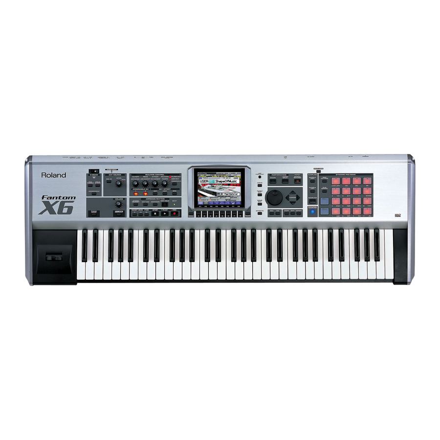
Page 4: Location Of Controls
Mar.2004 FANTOM-X6 LOCATION OF CONTROLS fig.panel-x6 [REAR] [TOP] 10 12... -
Page 5: Location Of Controls Parts List
Mar.2004 LOCATION OF CONTROLS PARTS LIST [TOP] PART CODE CATEGORY PART NAME DESCRIPTION Q’TY 03562134 CASING TOP PANEL 03562112 CASING DISPLAY COVER 03560889 DISPLAY UNIT KCG057QV1DB-G00 03565245 CASING DISPLAY ESCT 03565234 KNOB,BUTTON J R-KNOB SF-ELA BLK/SLV 03126167 POTENTIOMETER 12M/M ROTARY POTENTIOMETER EVJY10FB6A24 03565234 KNOB,BUTTON... - Page 6 FANTOM-X6...
-
Page 7: Exploded View
Mar.2004 EXPLODED VIEW fig.FANTOM-6_explo1_e... - Page 8 FANTOM-X6 fig.FANTOM-6_explo2_e...
- Page 9 Mar.2004 fig.FANTOM-6_explo3_e...
-
Page 10: Exploded View Parts List
NOTE:When you replace the MAIN BOARD ASSY for repairng, be sure to perform the "MAIN BOARD SETTING FOR SELECTING MODEL PROCEDURE"(to see P24). In addition, we supply the MAIN BOARD ASSY of FANTOM-X6 setting for spare parts. 72564245 PWB ASSY... -
Page 11: Wiring Diagram
Mar.2004 WIRING DIAGRAM fig.wiring-x6 D 2PIN POWER INLET INVERTER SWITCH BOARD A 2PIN BOARD BOARD CN102 CN403 C 2PIN E 20PIN B 7PIN H 50PIN CN20 CN21 CN10 F 34PIN EXPANSION PC CARD MAIN BOARD BOARD BOARD G 34PIN CN22 I 18PIN J 15PIN K 38PIN... - Page 12 FANTOM-X6...
-
Page 13: Parts List
Mar.2004 PARTS LIST fig.part1e CONSIDERATION ON PARTS ORDRING SAFETY PRECAUTIONS: When ordering any parts listed in the parts list, please specify the following items in the order sheet. The parts marked have PART NUMBER DESCRIPTION MODEL NUMBER safety-related characteristics. Use 22575241 Sharp Key C-20/50... - Page 14 NOTE: When you replace the MAIN BOARD ASSY for repairng, be sure to perform the "MAIN BOARD SETTING FOR SELECTING MODEL PROCEDURE"(to see P24). In addition, we supply the MAIN BOARD ASSY of FANTOM-X6 setting for spare parts. 72564245 PC CARD BOARD ASSY NOTE: ‘PC CARD BOARD ASSY’...
- Page 15 Mar.2004 03562223 UPD23C128040BLGY-819-MJH IC (MASK ROM) IC104 on MAIN BOARD 03124978 UPD23C128040ALGY-536-MJH IC (MASK ROM) IC28 on MAIN BOARD 03124989 UPD23C128040ALGY-535-MJH IC (MASK ROM) IC33 on MAIN BOARD 03560589 TC58DVM92A1TG00BBH IC (FLASH MEMORY) IC53 on MAIN BOARD ******** MBM29LV160BE70TN-E1 IC (FLASH MEMORY) IC19 on MAIN BOARD 03237689 M12L64164A-7T...
- Page 16 FANTOM-X6 TRANSISTOR 03126145 2SA933ASTPR TRANSISTOR Q2 on PANEL-A BOARD 15129626 2SD1468S TP Q TRANSISTOR Q3 on PANEL-A BOARD DIODE 01780045 RB051L-40 SCHOTTKY DIODE D4 on MAIN BOARD 15339130 MA142WK-(TX) ARRAY DIODE DA1,DA2,DA3,DA4 on JACK BOARD, DA8,DA6,DA7,DA9 on MAIN BOARD, DA503,DA505,DA502,DA501,DA504,DA51...
- Page 17 Mar.2004 RESISTOR 00567023 RPC05T 101 J MTL.FILM RESISTOR R45,R53,R71,R77,R156,R177,R184,R231,R31 on JACK BOARD ,R315,R316,R183,R246,R245,R187,R182,R18 1,R58,R57,R51,R320,R318,R54,R321,R331,R3 69,R370,R371,R372,R375,R378,R454,R317 on MAIN BOARD ,R505,R501,R504,R507,R508,R510,R511,R50 2 on PANEL-C BOARD 00567067 RPC05T 221 J MTL.FILM RESISTOR R80,R125,R82,R81,R79 on JACK BOARD ,R421,R422 on MAIN BOARD 00567112 RPC05T 471 J MTL.FILM RESISTOR R27,R21,R20,R26,R28,R29,R30,R57,R84,R91, R92,R100,R108,R25 on JACK BOARD...
- Page 18 FANTOM-X6 RESISTOR 01450490 NTH5G1M33B103J THERMISTOR RESISTOR R519 on PANEL-C BOARD 03128889 EXBV8V222JV RESISTOR-ARRAY RA502,RA503,RA504,RA501 on PANEL-C BOARD 15399561 RPC18T 330 J CARBON RESISTOR R61 on JACK BOARD 15399567 RPC18T 560 J CARBON RESISTOR 15399573 RPC18T 101 J CARBON RESISTOR R226 on JACK BOARD...
- Page 19 Mar.2004 CAPACITOR ,C103,C102,C101,C100,C98,C124,C143,C175 ,C173,C438,C170,C435,C169,C130,C144,C17 8,C142,C141,C140,C138,C137,C136,C135,C1 34,C133,C167,C413,C404,C336,C406,C407,C 408,C409,C410,C272,C412,C403 ,C334,C333,C307,C305,C299,C297,C280,C27 9,C439,C275,C411,C385,C340,C342,C343,C3 44,C346,C350,C352,C405,C372,C402,C387, C390,C391,C392,C393,C394,C396,C399,C40 0,C401,C353,C424,C230,C276,C420,C421,C4 22,C423,C229,C270,C227,C418,C425,C427,C 428,C429,C226,C430,C431,C432,C433,C434, C228,C241,C267,C261,C259,C257,C252,C24 8,C247,C419,C245,C417,C238,C237,C236,C2 33,C66, C231,C97,C414,C415,C416,C246,C36,C52,C 51,C50,C49,C48,C47,C45,C43,C42,C41,C40, C39,C53,C37,C14,C15,C16,C17,C18,C38,C96 ,C35,C20,C21,C6,C23,C30,C33,C34,C19,C20 0,C54,C70,C69,C68,C73,C77,C65,C64,C63,C 92,C93,C57,C56,C55,C74 on MAIN BOARD ,C521,C520,C519 on PANEL-C BOARD,C2 on PC CARD BOARD? 01674334 ECUV1H101JCV CERAMIC CAPACITOR C204,C75,C193,C191,C190,C91,C158,C203, C92,C143,C97,C96,C95,C94,C166,C77,C76,C 78,C79,C192,C93,C90,C80,C81,C87,C89,C88 ,C82,C86,C85,C84,C83 on JACK BOARD ,C232,C447,C139,C234,C240,C243,C265,C99...
- Page 20 FANTOM-X6 CAPACITOR 15369152 ECEV1CA100SR CHEMICAL CAPACITOR C4,C3,C2,C6,C25,C5,C17 on EXP BASE BOARD INDUCTOR, COIL, FILTER 03125167 SLF12565T-470M2R4 CHOKE COIL L1 on MAIN BOARD 03566334 EMI FILTER NFW31SP106X1E4L 01565578 N1608Z601T01 FERRITE-BEAD L21,L22,L23,L26,L27,L37,L29,L18,L30,L31,L 33,L35,L36,L28,L10,L1,L2,L3,L4,L5,L20,L7,L 19,L11,L12,L13,L14,L15,L16,L17,L34,L6,L32 on JACK BOARD, L36,L35,L34,L33,L32,L31,L30,L29,L28,L27,L 26,L8,L20,L24,L23,L7,L22,L6,L21,L25,L19 ,L14,L13,L12,L11,L10,L9,L37,L5 on MAIN...
- Page 21 Mar.2004 TRANSFORMER 03561389 EL-INVERTOR DHE1105B-5VE TRANSFORMER MOD401 on INVERTER BOARD PICKUP, SENSOR 03128767 PRESSURE SENSOR SHEET SCREW 40010345 SCREW M4X10 BINDING MACHINE FE BZC 40454045 SCREW 3X8 FLAT TAPTITEB NI FLANGE SOCKET 40011056 SCREW 3X6 BINDING TAPTITE B ZC 40011101 SCREW 3X8 BINDING TAPTITE B BZC 40011123...
- Page 22 FANTOM-X6...
-
Page 23: Main Board Setting For Selecting Model Procedure
Mar.2004 MAIN BOARD SETTING FOR Press the [F1],[F2] or [F3] to select the model. [F1]: 61keys -> Fantom-X6 SELECTING MODEL [F2]: 76keys -> Fantom-X7 [F3]: 88keys -> Fantom-X8 PROCEDURE Turn off and turn on the power again Turn on the power of the Fantom. -
Page 24: Users Data Save And Load
FANTOM-X6 USERS DATA SAVE AND TEST MODE LOAD The display sample is for Fantom-X7. about X6,X8 display portion of X7 is X6 and X7. Backing Up User Data (User Required equipment Backup) Monitor speakers Here’s how all user data in the user area can be saved on a memory card. -
Page 25: Version Check
Mar.2004 14. Pad Adjustment fig.test710_70 15. Pad Velocity Test 16. Pad Aftertouch Test 17. A/D Test 18. Keyboard Test 19. USB 20. Noise Test 21. Factory Reset 22. Completed 0. VERSION check When you enter Test mode, you will begin from the VERSION check item. fig.test710_70 Basic operation in Test mode Basic operation of the controls will be as follows. - Page 26 FANTOM-X6 2. DEVICE test fig.test714_70 This tests various devices located on the main board. When you enter the DEVICE test, the LCD display will show as follows, and device testing will begin automatically. fig.test712_70 If the test result is OK, you will automatically proceed to the next test item.
- Page 27 Mar.2004 7. Encoder fig.test684_70 When you enter the Encoder test, the LCD display will show as follows. fig.test659_70 One by one, press each switch shown in the LCD display. Verify that the indication in the LCD display for the corresponding switch becomes lighter.
- Page 28 FANTOM-X6 fig.test-lcd1_70 fig.test-sound1_70 When you press the [8] knob, you will proceed to the all-pixels-displayed test. Next you will test the circuitry of the [OUTPUT A R] jack. The LCD display will show as follows. Connect the stereo side of the PCS-31 to the [OUTPUT A R] jack, connect the fig.test647_70...
- Page 29 Mar.2004 13. D-Beam test fig.test-sound4_70 This tests the operation of the [D BEAM] controller. When you begin the D-Beam test, the LCD display will show as follows. fig.test623_70 Press the [8] button to proceed to the next test item. 12. D-Beam Adjustment test First you will test the [D BEAM] controller.
- Page 30 FANTOM-X6 fig.test-pad-adj1_70 fig.test769_70 Using the push-pull gauge you provided, apply pressure of 3 (kgf) to Strongly and slowly press each [DYNAMIC PAD] from [1] through [16]. [DYNAMIC PAD 4]. Verify that the LED of the [DYNAMIC PAD] you press changes from blinking...
-
Page 31: Factory Reset
Mar.2004 18. Keyboard Connect a USB cable to your computer (one that has a USB connector; the OS can be either Windows Me, Windows 2000, or Windows XP). This tests the keyboard. If the test result is OK, the display will indicate “Status: Connect USB Test When you enter the keyboard test, the LCD display will show as follows. -
Page 32: Restoring The Factory Settings
FANTOM-X6 SYSTEM SOFTWARE UPDATE fig.test778_70 PROCEDURE The Fantom-X uses flash memory as its program ROM, and can be updated using either of the following two methods. 1. Updating from a computer via a USB cable (Time required: approximately 3 minutes) 2. -
Page 33: Required Items
14. Insert the UPDATE CD-ROM (#17041420) into your computer, and navigate to the “Roland” folder of the CD-ROM. 15. Copy the file “fanx.bin” file (located within the “Roland” folder) to the Fantom-X (removable disk). The Fantom-X will receive the data from the computer. - Page 34 Insert the UPDATE CD-ROM (#17041420) into your computer, and navigate to the “Roland” folder within the CD-ROM. Copy the entire “Roland” folder with its contents onto the PC card. Turn on the power of the Fantom-X. Press the [MENU] button to access the Menu window.
-
Page 35: Keyboard Parts List
Mar.2004 KEYBOARD PARTS LIST fig.sk-961-L-4... -
Page 36: Keyboard Circuit Board
FANTOM-X6 KEYBOARD CIRCUIT BOARD fig.keyboard-board... -
Page 37: Keyboard Circuit Diagram
Mar.2004 KEYBOARD CIRCUIT DIAGRAM fig.keyboard-circit... -
Page 38: Keyboard Disassembly
FANTOM-X6 KEYBOARD DISASSEMBLY <Attaching the RUBBER SWITCHES and PCB> To fasten the SK-9 PWB, be sure to use 3*10mm BINDING VWH (PART No.40233545). Turn the chassis over as shown in fig.1. Next, place 4 pieces of RUBBER SWITCH 12P in turn, on the chassis from the left end (the bass side of keyboard), aligning them with the long holes provided on the chassis. - Page 39 Mar.2004 Aligning the cutouts in the PWB with the lugs on the chassis, put one side of the PCB into the chassis hooks. Place the PCB on the Chassis so that the chassis positioning pins fit into the positioning holes. (See fig.3) At this point, the chassis positioning reference pin should first be fitted into the hole. There are two PCBs, LOW and HI, as shown in fig.4.
- Page 40 FANTOM-X6 <Key removal> Hold the tip of the key, put pliers into the bearing side, and spread out. (Refer to fig.6) fig.6-e <Key installation> Place a spring on the chassis. Next, place a key (see fig.7) and press the bearing side.
-
Page 41: Block Diagram
Mar.2004 FANTOM-X6 BLOCK DIAGRAM fig.block PANEL-A,B,C BOARD LCD UNIT PCMCIA BOARD COLOR LCD PC CARD D-Beam QVGA DynamicPAD 320x240dot LCDBOARD DC-AC INVERTER DHE1105-5VE 20.000MHz SDRAM Flash ROM Flash ROM IC2,IC6 H8/3061 128Mbit x 2 IC53 IC19 20MHz LCDC 16Mbit Work RAM... -
Page 42: Circuit Board(Main 1)
Mar.2004 CIRCUIT BOARD(MAIN 1) fig.b-x678-main1 View from components side... -
Page 43: Circuit Board(Main 2)
FANTOM-X6 CIRCUIT BOARD(MAIN 2) fig.b-x678-main2 View from foil side... -
Page 44: Circuit Diagram(Main 1)
Mar.2004 FANTOM-X6 CIRCUIT DIAGRAM(MAIN 1) fig.c-x678-main1 D[31..0] BD[15..0] D[31..0] BD[15..0] A[25..0] BA[15..0] A[25..0] BA[15..0] EEPDI 3. 3 HD6417706F133 IC19 DQ15/A-1 3. 3 XWE3 XWE3 RA88 R341 WE3/DQMUU/ICIOWR/PTC[2] DQ14 XWE2 XWE2 R342 WE2/DQMUL/ICIORD/PTC[1] DQ15 DQ13 XWE1 XWE1 RA12 BS/PTC[0] A10/AP DQ14 DQ12 3. -
Page 45: Circuit Diagram(Main 2)
Mar.2004 FANTOM-X6 CIRCUIT DIAGRAM(MAIN 2) fig.c-x678-main2 BD[15..0] C222 C224 C225 C226 C227 IC47A C228 XBRD C229 XSMRE XSMBUS IC47B XNDBUS R133 R134 SmartMedia XBWE0 C230 XSMWE 2.2k IC128 8bit_single_color BA[15..0] 24FMN-BMTTN-TF S1D13705F00A (Format-2) IC129A SMDIR XWPSW AB16 BA15 SMCLE XWPSW... -
Page 46: Circuit Diagram(Main 3)
Mar.2004 FANTOM-X6 CIRCUIT DIAGRAM(MAIN 3) fig.c-x678-main3 C397 EEE-A@SP 3. 3 C398 EEE-A@SP 100/6.3 100/6.3 C399 C400 C401 C402 C403 C404 IC20 10/16 C166 3. 3 C405 C406 IC28 DSA11 DD31 EEE-S@SR DQ15 C407 C408 WA23 WD15 DSA10 DD30 34FMN-BMTTN-TF O15/A-1... -
Page 47: Circuit Diagram(Main 4)
Mar.2004 FANTOM-X6 CIRCUIT DIAGRAM(MAIN 4) fig.c-x678-main4 MA147-(TX) R159 4.7k IC58 BIAS + 15 TA7805F R161 C266 C267 4.7k C270 C271 C272 C273 10/16 10/16 10/16 DIR_INL R407 R163 R162 MCR50J@ R164 4.7k C274 R165 R166 R167 2SK880GR TER1 TER2 TER3... -
Page 48: Circuit Diagram(Main 5)
Mar.2004 FANTOM-X6 CIRCUIT DIAGRAM(MAIN 5) fig.c-x678-main5 BA[10..0] BA[10..0] PC-D[0..15] 3. 3 BD[15..0] C428 C429 BD[15..0] PC-A[0..25] CARD_POWER PC-D10 PC-D11 PC-D9 PC-D8 BD10 PC-D8 PC-D9 RA104 BD11 PC-D11 PC-D10 100k BD12 PC-D12 PC-D13 BD13 PC-D13 PC-D14 BD14 PC-D14 PC-D15 IC113A BD15... -
Page 49: Circuit Board(Panel-A Keytop, Panel-B Keytop)
Mar.2004 FANTOM-X6 CIRCUIT BOARD(PANEL-A KEYTOP, PANEL-B KEYTOP) fig.b-x678-panel View from components side ”scale=0.95 ”... -
Page 50: Circuit Diagram(Panel-A Keytop, Panel-B Keytop)
Mar.2004 FANTOM-X6 CIRCUIT DIAGRAM(PANEL-A KEYTOP, PANEL-B KEYTOP) fig.c-x678-panel-a To:JACK BOARD CN5 100/16 OUTSEND_R 1SS133 1SS133 1SS133 1SS133 1SS133 1SS133 1SS133 1SS133 PADTRIGGER SOLOSYNTH INPUTS ASSIGN1 ASSIGN2 -OCT +OCT OUTSEND_L 100/16 EVQ11A05R EVQ11A05R EVQ11A05R EVQ11A05R EVQ11A05R EVQ11A05R EVQ11A05R EVQ11A05R (+5V) VR1A... -
Page 51: Circuit Board(Lcd, Inverter, Jack, Panel-C Keytop, Inlet)
Mar.2004 FANTOM-X6 CIRCUIT BOARD(LCD, INVERTER, JACK, PANEL-C KEYTOP, INLET) fig.b-x678-jack-t Not Used Not Used View from components side ”scale=0.95 ”... -
Page 52: Circuit Board(Lcd, Inverter, Jack, Panel-C Keytop, Inlet)
Mar.2004 FANTOM-X6 CIRCUIT BOARD(LCD, INVERTER, JACK, PANEL-C KEYTOP, INLET) fig.b-x678-jack-b Not Used Not Used View from foil side ”scale=0.95 ”... -
Page 53: Circuit Diagram(Jack 1)
Mar.2004 FANTOM-X6 CIRCUIT DIAGRAM(JACK 1) fig.c-x6-jack1 N1608Z to MAIN N1608Z N1608Z MNR14@ IC1G N1608Z board N1608Z HD74LV14ATELL N1608Z XRST_SUB ENC_B IC1E N1608Z HD74LV14ATELL XRST5 XRST_IN XRST_SUB IC1A IC1B SH3_TXD0 MNR14@ H8S_RXD1 HD74LV14ATELL HD74LV14ATELL SH3_RXD0 H8S_TXD1 0.01 SH3_XCTS2 H8_XCTS IC1C IC1D... -
Page 54: Circuit Diagram(Jack 2)
Mar.2004 FANTOM-X6 CIRCUIT DIAGRAM(JACK 2) fig.c-x6-jack2 for SK961 for PA-5 RA13 RA15 SC10 SC10 RA12 CN14 PR10 PR10 D[0..7] C31 NIU C32 NIU C33 NIU C34 NIU RA16 C35 NIU C36 NIU SC10 RA14 C37 NIU PR10 C38 NIU MNR14@... -
Page 55: Circuit Diagram(Jack 3)
Mar.2004 FANTOM-X6 CIRCUIT DIAGRAM(JACK 3) fig.c-x6-jack3 to PANEL A LS[0..3] LLS5 LLD4 LLS4 LD[0..7] LLD3 TC74VHC138F LLD7 LLD2 RN2427 LLD5 LLD1 LLD6 SD[0..7] RN2427 C194 SSS5 BEAT_GREEN RN2427 IC22 BEAT_RED TC7S04F LLD0 DBPLUS_OUT SSS4 DBPLUS 330/16 LLS6 RN2427 SSS3 + 15... -
Page 56: Circuit Diagram(Jack 4)
Mar.2004 FANTOM-X6 CIRCUIT DIAGRAM(JACK 4) fig.c-x6-jack4 MA147-(TX) 100k IC21A N1608Z HOLD NJM2904M C108 C104 HOLD C109 C110 0.01 N1608Z YKB21-5074 IC11 L10 N1608Z YKF51-5041 N1608Z R231 PC410LK RN2307 MA147-(TX) N1608Z 4.7k MIDI_IN C224 L12 N1608Z 1000P L13 N1608Z L14 N1608Z... -
Page 57: Circuit Diagram(Jack 5)
Mar.2004 FANTOM-X6 CIRCUIT DIAGRAM(JACK 5) fig.c-x6-jack5 R227 + 15 R228 TO PANEL BOARD A (AUDIO) R111 CN18 + 15 5.6K R112 5.6K CN10 COA_IN C127 C225 C128 AUDIO_IN_RTN_L 100/25 AUDIO_IN_RTN_R C129 NIU TER1 TER2 TER3 R114 R188 AUDIO_IN_SEND_R MCR50J MCR50J... -
Page 58: Circuit Diagram(Panel-C Keytop)
Mar.2004 FANTOM-X6 CIRCUIT DIAGRAM(PANEL-C KEYTOP) fig.c-x6-panel-c DA501 WRITE PTN501 PTN502 PTN503 PTN504 SW501 EVQ11A05R CBN-M-1 CBN-M-1 CBN-M-1 CBN-M-1 PAD-13 PAD-14 PAD-15 PAD-16 MA142WK-(TX) PAD15 PAD15 PAD14 PAD11 RA501 PAD13 PAD07 EXBV8V@JV DA502 DA503 DA504 DA505 PAD12 PAD03 2.2k MIXER LAYER... -
Page 59: Circuit Diagram(Lcd)
Mar.2004 CIRCUIT DIAGRAM(LCD) fig.c-x6-lcd 3. 3 C301 ECEA-KS@ C302 L301 N1608Z@T01 3. 3 L302 N1608Z@T01 L303 N1608Z@T01 From:Main Board To:LCD L304 N1608Z@T01 IC301 CN20 CN301 CN302 3. 3 3. 3 LOAD DISP CONTRAST VCONT HD74LV245ATELL L305 N1608Z@T01 L306 N1608Z@T01 L307 N1608Z@T01 L308 N1608Z@T01... -
Page 60: Circuit Diagram(Inverter)
FANTOM-X6 CIRCUIT DIAGRAM(INVERTER) fig.c-x6-inver C404 C405 RA2-V@M RPE@ + 15 CN401 CN402 B7B-XH-A B8B-XH-A NIU - 1 5 CN404 MOD401 FL401 CN403 C402 C401 C403 RPE@ RA2-V@M RPE@ 100/16 SS11V-10062 B2B-PH-K-S B2(4-2R3)B-XH-A DHE1105-5VE CIRCUIT DIAGRAM(INLET) fig.c-x6-inlet SW601A CN601 SDKLA1-B JK601... -
Page 61: Circuit Board(Exp Base)
Mar.2004 CIRCUIT BOARD(EXP BASE) fig.b-x678-exp2 View from components side fig.b-x678-exp1 View from foil side... - Page 62 FANTOM-X6...
-
Page 63: Circuit Diagram(Exp Base)
Mar.2004 FANTOM-X6 CIRCUIT DIAGRAM(EXP BASE) fig.c-x678-exp 3 . 3 3WA23 TWA23 EWA23 3WA22 TWA22 EWA22 3WA21 TWA21 EWA21 3WA20 TWA20 EWA20 3WA19 TWA19 EWA19 To:MAIN BOARD 3WA18 TWA18 EWA18 D 3 . 3 3. 3 10/16 3 . 3 3 . 3 3 . -
Page 64: Circuit Board(Pc Card 1)
Mar.2004 CIRCUIT BOARD(PC CARD 1) fig.b-x678-pc1 View from foil side CIRCUIT BOARD(PC CARD 2) fig.b-x678-pc2 View from components side... -
Page 65: Circuit Diagram(Pc Card)
FANTOM-X6 CIRCUIT DIAGRAM(PC CARD) fig.c-x678-pc PC-CARD SLOT PC-D3 PC-CD1 PC-D4 PC-D11 PC-D5 PC-D12 PC-D6 PC-D13 PC-D7 PC-D14 CE1A PC-A10 PC-D15 PC-A9 PC-A10 PC-A8 CE2A PC-A7 CARD_XRD PC-A6 CARD_XIORD PC-A5 PC-A9 PC-A4 CARD_XIOWR PC-A3 PC-A8 PC-A2 CARD_XWR PC-A1 PC-A0 PC-A7 CARD_POWER... -
Page 66: Error Messages
The contents of memory may have been damaged. Please perform the Factory Reset operation. If this does not resolve the problem, please contact your dealer or the nearest Roland Service Center. Memory Full! Saving is not possible because there is insufficient space Delete unneeded data.
Need help?
Do you have a question about the Fantom-X6 and is the answer not in the manual?
Questions and answers