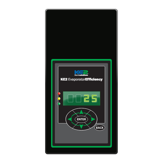
KE2 Therm Solutions Evaporator Efficiency Installation Instructions Manual
Hide thumbs
Also See for Evaporator Efficiency:
- Installation manual (20 pages) ,
- Quick start manual (20 pages) ,
- Installation instructions manual (16 pages)
Table of Contents
Advertisement
KE2 EvaporatorEfficiency
Installation Instructions
Providing Advanced Energy Saving Technology
for Commercial Refrigeration and AC Systems.
Installation N.1.1
Benefits of KE2 Smart Access
It's easier than ever to set up every controller you
service to provide alarm notifications via text or
e-mail
KE2 Smart Access auto connects, and can
eliminate the need for costly IT support
Easy setup of remote monitoring & system
control
Doesn't require port forwarding or a vpn
Customized dashboard lets you remotely view all
the controllers on one page
KE2 Therm Solutions
July 2015
Advertisement
Table of Contents

Summary of Contents for KE2 Therm Solutions Evaporator Efficiency
- Page 1 Easy setup of remote monitoring & system control Doesn’t require port forwarding or a vpn Customized dashboard lets you remotely view all the controllers on one page KE2 Therm Solutions Providing Advanced Energy Saving Technology for Commercial Refrigeration and AC Systems.
-
Page 2: Table Of Contents
Page 11 (1) Air sensor mount Figure 6: Evaporator Efficiency Diagram ....Page 6 (5) Self-tapping screws Figure 7: Typical Piping Diagram - Hot Gas ... . . Page 7 (1) Installation Instructions Figure 8: Wiring Schematic - New Install . -
Page 3: Location
8 inches from the coil surface. thermsolutions KE2 EvaporatorEfficiency Figure 2 - Return Air Sensor Placement ENTER BACK ~2/3 down from top At the entrance 8-10” Sensor KE2 EvaporatorEfficiency thermsolutions ENTER BACK Return Air ©Copyright 2015 KE2 Therm Solutions, Inc., Washington, Missouri 63090... -
Page 4: Defrost 2
An alternate method of positioning places the sensor vertically between the coil fins. Figure 5 shows the proper way to secure the coil sensor. ©Copyright 2015 KE2 Therm Solutions, Inc., Washington, Missouri 63090... -
Page 5: Mounting The Controller
The relay is not intended to control the compressor directly. It mounting tab allowing the controller to install over the screws. is designed to be used to control the liquid line solenoid or as ©Copyright 2015 KE2 Therm Solutions, Inc., Washington, Missouri 63090... - Page 6 Pressure Transducer Part Number black 20222 Beacon brown Wiring Detail Beacon® II green replacement white controller green black required. signal Pressure Transducer ground Temperature Sensors (4) Beacon® II blue white black ©Copyright 2015 KE2 Therm Solutions, Inc., Washington, Missouri 63090...
- Page 7 Defrost Solenoid Valve KE2 Evap Additional circuits thermsolutions KE2 EvaporatorEfficiency ENTER BACK Note: Controllers must be bonded and MULTI EVAP DEFROST setpoint must be set to INDEPENDENT Piping shown for illustration purposes only. ©Copyright 2015 KE2 Therm Solutions, Inc., Washington, Missouri 63090...
- Page 8 N.1.1 July 2015 Page 8 KE2 EvaporatorEfficiency Installation Instructions Figure 8 - Wiring Schematic - Controller New Install ©Copyright 2015 KE2 Therm Solutions, Inc., Washington, Missouri 63090...
- Page 9 N.1.1 July 2015 Page 9 KE2 EvaporatorEfficiency Installation Instructions Figure 9 - Wiring Schematic - Controller with KE2 Contactor Box ©Copyright 2015 KE2 Therm Solutions, Inc., Washington, Missouri 63090...
-
Page 10: Dimensions
N.1.1 July 2015 Page 10 KE2 EvaporatorEfficiency Installation Instructions Figure 10 - KE2 Evaporator Efficiency - Dimensions (front view) Dimensions - Inches Depth 2.45” Pressure Transducer 5.75 0.95 0.67 2.03 1.40 2.03 female 1/4” SAE with 11.75 6.75 depressor Temperature Sensor 0.187... -
Page 11: Controller Setup
The controller will prompt the user for a password PASSWORD when the user attempts to access set- points they do not have permission to change. ©Copyright 2015 KE2 Therm Solutions, Inc., Washington, Missouri 63090... - Page 12 6 The Setpoint parameters shown TEMP UNITS in BOLD ITALIC are used for AIR TEMP DIFF bonded controllers only. EXTREME TEMP DIFF PROPORTIONAL 7 Only displayed when Run Time INTEGRAL Defrost is selected. DERIVATIVE ©Copyright 2015 KE2 Therm Solutions, Inc., Washington, Missouri 63090...
-
Page 13: Manual Menu
ONLY FOR SITEVIEW MANAGER: No communication to the ftp server defined in Settings/Logging Options SNTP COMMUNICATION ALARM ONLY FOR SITEVIEW MANAGER: No communication to the SNTP server defined in Settings/Siteview Options ©Copyright 2015 KE2 Therm Solutions, Inc., Washington, Missouri 63090... -
Page 14: Setpoint Menu
N.1.1 July 2015 Page 14 KE2 EvaporatorEfficiency Installation Instructions Setpoints Menu Parameter Name Description ROOM TEMP Walk-in freezer or cooler room temperature to be maintained Method of defrost used on the evaporator coil: Electric, Air, Hot Gas with Liquid Line Solenoid/Compressor relay off, Hot Gas with DEFROST TYPE Liquid Line Solenoid/compressor relay on VALVE TYPE... - Page 15 N.1.1 July 2015 Page 15 KE2 EvaporatorEfficiency Installation Instructions Range Default Current -50°F to 90°F -10°F ELEC, AIR, HOT GAS COMP ON, HOT GAS COMP OFF ELEC MECHANICAL, KE2 RSV, KE2 HSV, SER/SEI 1 TO 20, SER B TO L, SEI 30, SEI 50, SEH, ETS12 TO 50, MECHANICAL ETS100, ETS250/400, CAREL, CUSTOM;...
-
Page 16: Communication
Sensor Specs: -60° to 150°F moisture resistant package KE2 Therm Solutions, Inc. ©Copyright 2015 KE2 Therm Solutions, Inc., Washington, Missouri 63090 Bulletin N.1.1 July 2015 supersedes Bulletin N.1.1 June 2015 and all prior publications. 12 Chamber Drive . Washington, MO 63090...


Need help?
Do you have a question about the Evaporator Efficiency and is the answer not in the manual?
Questions and answers