Table of Contents
Advertisement
Quick Links
Advertisement
Table of Contents

Related Manuals for Askey RAC2V1K


Summary of Contents for Askey RAC2V1K
- Page 1 Wireless Router User Manual...
-
Page 2: Table Of Contents
Table of Contents 1 Hardware Setup ......................3 1.1 Getting to know your router ................. 3 1.2 Unpack Router’s box .................... 4 1.3 Hardware Features ....................5 1.3.1 Front Panel ..................... 5 1.3.2 Rear Panel ...................... 6 1.4 Position Your Router.................... 7 2 Normal User Settings .................... - Page 3 3.2 Router ....................... 114 3.2.1 Static Routing .................... 114 3.2.2 Dynamic Routing ..................116 3.2.3 Multiple NAT .................... 117 3.3 TR-069 ......................118 3.4 Operation Mode ....................119 3.4.1 Wireless Router Mode ................120 3.4.2 Access Point Mode ..................120 3.4.3 Media Bridge Mode ...................
-
Page 4: Hardware Setup
1 Hardware Setup 1.1 Getting to know your router This product is designed for new flagship service: Managed Service Home Router. Managed Service Home Router provides: 1. High performance: Dual-Core ARM up to 1.7G/1GB DDR RAM. Dual-Band wireless up to AC2550 (2.4G 200M * 4 + 5G 433M * 4). Gigabyte 2x WAN/ 4x LAN Ethernet ports. -
Page 5: Unpack Router's Box
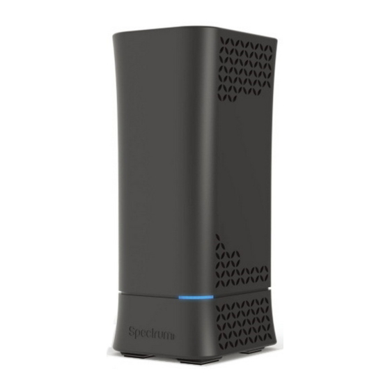
1.2 Unpack Router’s box Open the box and remove the router, cables, and installation guide. Wireless router Ethernet Cable Power Adapter Figure 1. Check the package contents The box contains the following items: Wireless router. AC power adapter (plug varies by region). Ethernet cable. -
Page 6: Hardware Features
1.3 Hardware Features Before setup please take a moment to become familiar with the label and front, side, and back panels of your router. Pay particular attention to the LED on the front panel. 1.3.1 Front Panel The router front and side panels feature the status LED and buttons as shown in the following figure. -
Page 7: Rear Panel
connection). Blue alternate blinking: Updating firmware (or any scenario where device must not be restarted). solid: Critical issues (hardware or otherwise). LED on front of device will dim to low (65%) when there is no settings activity or connectivity issues for 120 hours. If any settings are changed or connectivity issues occur LEDs will return to normal (100%) brightness. -
Page 8: Position Your Router
WAN Port: Connect a network cable for WAN (Wide Area Network) connection. This connects the Ethernet and other access lines e.g. modem. USB 3.0 Port: Connect a USB Printer, U-Disk or USB drive. For printer and folder sharing, reference Services on page 19. Power Port(DC-IN): Use the bundled AC adapter to connect your router to a power source. -
Page 9: Normal User Settings
2 Normal User Settings The wireless router contains an intuitive graphical user interface (GUI) based on web, which allows administrator to easily configure its features through a web browser. 2.1 Login 1. Open a web browser, then key in the router’s default IP address: http://192.168.1.1, and click Enter key in the keyboard;... - Page 10 On the right top side, there are two command buttons: Change Password and Logout. It’s highly recommended to click the Logout button who locates on the right top side when administrator intends to leave the webpage. When Change Password button has been clicked, the browser will navigate administrator to corresponding webpage.
-
Page 11: Wizard Setup
On this page, administrator should just type in new password in New Password and Retype New Password, then click Apply button. 2.2 Wizard Setup The wizard can navigate administrator to configure basic settings for wireless router, which makes it become easy enough to set up the router. Internet Setup After administrator has clicked the Wizard button, the Internet Setup page will come up. - Page 12 used by cable modem service providers. WAN MAC: MAC address of WAN port. Some ISPs monitor devices’ MAC address who are connecting to their networks, and only these devices with a valid MAC address can be served. If router can’t get access to internet, administrator can do either of the followings: * Contact your ISP and request to update the MAC address associated with your ISP subscription.
- Page 13 password. If you have no idea of the username and password, please contact your ISP. Username: This field is only available when you set the WAN Connection Type as PPPoE, PPTP or L2TP. Password: This field is only available when you set WAN Connection Type as PPPoE, PPTP or L2TP.
- Page 14 their services, and will disallow Internet connection for invalid MAC addresses. Click Next. Note: All of the parameters in Static IP connection type should be provided by your ISP. If you have no idea of them, please ask the ISP for help. 4.
- Page 15 Gateway: If your WAN connection requires a static IP address, type in the gateway IP address in this field. Connect to DNS Server: Select Yes to let the device connect to a DNS Server automatically, or No to enter DNS address manually below. DNS1 &...
-
Page 16: Network Setup
Network Setup After you have clicked Next icon in Internet Setup page, you comes here. 1. SSID: Name for a wireless network, that’s to say it’s used to identify a wireless network. Wi-Fi devices automatically detect all networks within its communication range, if they own the key. - Page 17 Config Overview After click the Apply icon, administrator comes to Config Overview page, which displays a summary of configuration information. If the settings are all correct, administrator should click Apply icon.
-
Page 18: Basic Setup
2.3 Basic Setup 2.3.1 My Router From the navigation panel, go to Basic > My Router. Note: The Reset Icon in the picture is used to restart/reboot router manually! Wireless: This module is implemented to configure some basic settings for router’s wireless connection. -
Page 19: Wps Setup
automatically detect all networks within its communication range. The maximum length of a SSID is 32 characters. 2. Key: A string used for connection authentication. Its length ranges from 0 to 63 characters(letters, numbers or a combination) or from 8 to 64 hex digits. 3. - Page 20 Note: Authentication methods supported by WPS are: Open system, WPA-Personal and WPA2-Personal. Not supported methods are: Shared Key, WPA-Enterprise, WPA2-Enterprise and RADIUS. 4. Connection Status 愪 The connection status of WPS. 5. Configured: The configured status of WPS. 6. AP PIN Code: Key in the router's PIN code in the client's WPS utility and configure the network name and security settings.
-
Page 21: Lan Setup
2.3.3 LAN Setup This module makes it easier for administrator to modify the default LAN IP Address. Steps to modify LAN IP settings: 1. From the navigation panel, go to Basic > My Router. 2. LAN IP: The LAN IP address of the wireless router. Its default value is 192.168.1.1. -
Page 22: Wan Setup
2.3.4 WAN Setup Click WAN button to configure the WAN connection settings: 1. Connection Type: Choose the Internet Service type. There are five options are DHCP, PPPoE, Static, PPTP, and L2TP. Consult your ISP if you are unsure what kind of WAN connection type to select. 2. - Page 23 DNS 1 & DNS 2: Either of them indicates IP address of a DNS server. Click Apply. 3. If you select PPPoE: Username: This field is only available when you set the WAN Connection Type as PPPoE, PPTP or L2TP. Password: This field is only available when you set WAN Connection Type as PPPoE, PPTP or L2TP.
- Page 24 4. If you select Static, below show the steps to set IP: If WAN connection requires a static IP address, key in the IP address in • this field. Subnet Mask: If WAN connection requires a static IP address, key in the •...
- Page 25 5. If you select PPTP: Username: This field is only available when you set the WAN Connection • Type as PPPoE, PPTP or L2TP. Password: This field is only available when you set WAN Connection Type • as PPPoE, PPTP or L2TP. Get the WAN IP Automatically: Select Yes to get WAN IP automatically •...
- Page 26 6. If you select L2TP: Please reference to PPTP above for relevant settings descriptions and enter the required information.
-
Page 27: Parental Control
2.3.5 Parental Control Parental Control allows administrator to control the behavior of the router. Steps to set parental control function: 1. From the navigation panel, go to Base > Parental Control. 2. Enable Parental Control: Select On to enable parental control, Select Off to disable parental control. - Page 28 3. Client Name: Select client from the list. The name in the list stands for the client that is communicating with the router. 4. Client MAC: MAC address of the selected client. Note: Client Name just makes it easier for administrator to distinguish lan-side devices.
-
Page 29: Services
2.3.6 Services 2.3.6.1 USB Printer Sharing USB Printer sharing allows administrator to plug a USB printer to router’s USB port and set up the print server. Steps to set up USB Printer sharing: From the navigation panel, go to Basic > Service > USB Printer sharing > Add Printer. - Page 30 the upload button. 4. Printer tab displays whether your printer is operating correctly with the print server, as below. To check whether your printer is working correctly or not, input the LAN address (192.168.1.1) for the printer in Windows Finder. Double-click the printer icon and if you see the status interface as shown below, the installation was successful.
-
Page 31: Ftp Server
You can view print status information in the Print Jobs tab. Active: All active jobs, including processing and pending jobs. Processing: The job currently processing/communicating print data. All Jobs: All print jobs. 2.3.6.2 FTP Server FTP Server enables an FTP server to share files from USB disk to other devices via your local area network or via the Internet. - Page 32 Display information on FTP Server: 1. From the navigation panel, go to Basic > Services > FTP Server. 2. Connect an external USB hard disk drive or USB flash drive to your router, and your device will be displayed here. 3.
- Page 33 From the navigation panel, go to Basic > Services > Samba Server. Connect an external USB hard disk drive or USB flash drive to your router, and your device will be displayed here. Enable Share: Click the On/Off to enable/disable Internet access to Samba service.
- Page 34 2.3.6.4 WebDAV The client can write operations in WebDAV directory with appropriate permissions. This page shows information about the WebDAV Server. To set up WebDAV go to Advanced > Servers > WebDAV. 1. From the navigation panel, go to Basic > Services > WebDAV Server. 2.
- Page 35 the local area network (default value: 80). 4. HTTPS Access Port: The port to access the WebDAV server for HTTPS protocol in the local area network (default value: 443). 5. Enable Outside Access: Select On/Off to enable/disable access to WebDAV server by wide area network.
- Page 36 your device will be displayed here. 3. Enable DLNA Media Server: Switch DLNA media server on or off. 4. Media Server Name: The DLNA server's name, which will be displayed by the media player such as VLC or Windows Media Player. 5.
- Page 37 2.3.6.7 NFS Network File System Server is used to share the USB disk with clients via network. Clients can mount the remote disk to a local directory for a faster speed than using a Samba server. This page shows information about the NFS Server. To setup NFS, go to Advanced >...
-
Page 38: System
2.3.7 System The system module allows administrator to configure router. Administrator can change the username and password used to login to the router GUI and other miscellaneous settings such as Time Zone, Auto Logout and NTP Server. Steps to set the System settings: 1. -
Page 39: Advanced Setup
8. Click Apply. 2.4 Advanced Setup 2.4.1 Network 2.4.1.1 WAN Settings 2.4.1.1.1 Internet Settings Router supports several WAN connection types. Select the type from the WAN Connection Type dropdown menu. - Page 40 Steps to configure WAN connection settings: 1. From the navigation panel, go to Advanced > Network > WAN > Internet. 2. WAN Connection Type: Choose the Internet Service Provider type. There are 5 options: DHCP, PPPoE, Static , PPTP, and L2TP. If you are unsure which type to select, please consult your ISP.
- Page 41 unset, pppd uses the first discovered one. 15. Additional Pppd Options: Additional command line arguments to pass to the pppd daemon. 16. Host Name: This field allows you to provide a host name for your router. It is usually provided by ISP. 17.
- Page 42 Steps to set up DDNS: 1. From the navigation panel, go to Advanced > Network > WAN > DDNS. 2. Enable the DDNS Client: Yes means enable DDNS function, No means disable DDNS function. 3. Server: Select the Supported DDNS provider’s URL from the list. Host Name: Specifies the host name to be updated.
-
Page 43: Port Trigger
systems) to be controlled via an IP-based network with or without a central control unit. Under the help of UPnP, one device can be discovered once it has connected to network, then device can be remotely configured to support P2P applications, interactive gaming, video conferencing, and web or proxy servers. - Page 44 Steps to set up Port Trigger: From the navigation panel, go to Advanced > Network > WAN > Port Trigger. Enable Port Trigger: Check to enable or disable Port Triggering. Well-Known Applications: Select popular games and web services to add to the Port Trigger List.
-
Page 45: Port Forward
2.4.1.1.5 Port Forward Port forwarding is a method used to direct network traffic from Internet to a specified port. Setting up Port Forwarding allows traffic from outside to get access to specified services provided by lan-side device. NOTE: When Port Forward is enabled, router blocks unsolicited inbound traffic from the Internet and only allows replies from outbound requests from the LAN. - Page 46 7. Port Range: Defines the range of port in wan side. NOTES: A network makes use of ports in order to exchange data, with each port assigned a port number and a specific task. For example, port 80 is used for HTTP. A specific port can only be used by one application or service at a time.
- Page 47 Port triggering will work even without setting up a specific LAN IP address. Unlike port forwarding, which requires a static LAN IP address, port triggering allows dynamic port forwarding using the router. Predetermined port ranges are configured to accept incoming connections for a limited period of time. Port triggering allows multiple computers to run applications that would normally require manually forwarding the same ports to each PC on the network.
- Page 48 Steps to set up DMZ: 1. From the navigation panel, go to Advanced > Network > WAN > DMZ. 2. Enable DMZ: Check to enable or disable DMZ. 3. IP Address of Exposed Station: LAN IP address of a client who can provide DMZ service.
- Page 49 2.3.1.1.7 NAT Pass Through NAT Pass Through allows a Virtual Private Network (VPN) connection to pass through the router to the network server. Steps to set up NAT Pass Through: To configure NAT Pass Through settings, go to Advanced > Network > WAN > NAT Pass Through.
- Page 50 protocol suite for securing Internet Protocol (IP) communications by authenticating and encrypting each IP packet of a communication session. SSL Passthrough: Secure Sockets Layer(SSL) is cryptographic protocols that provide communications security over a computer network. RTSP Passthrough: Enable or disable. The Real Time Streaming Protocol (RTSP) is a network control protocol designed for use in entertainment and communications systems to control streaming media servers.
-
Page 51: Lan Settings
2.4.1.2 LAN Settings 2.4.1.2.1 LAN The LAN IP module allows administrator to modify lan-side IP address of the router. Steps to modify the LAN IP settings: 1. From the navigation panel, go to Advanced > Network > LAN > LAN IP. 2. -
Page 52: Dhcp Server
2.3.1.2.2 DHCP Server DHCP server can assign each client an IP address and informs the client of DNS server’s IP, default gateway’s IP and etc. This wireless router can allocate up to 253 IP addresses for lan-side devices. Steps to configure the DHCP server: 1. - Page 53 Server. This field only contains alphanumeric characters and dash symbols. 4. IP Pool Starting Address: Starting address that can be allocated to lan-side devices. 5. IP Pool Ending Address: Ending address that can be allocated to lan-side devices. 6. Lease Time: Defines the time that lan-side devices can use the assigned IP address.
-
Page 54: Wireless Settings
2.4.1.3 Wireless Settings 2.4.1.3.1 Basic Basic settings allow you to set up the basic wireless settings. Steps to set up the basic wireless settings: 1. From the navigation panel, go to Advanced > Network > Wireless > Basic Basic. Basic Basic 2. - Page 55 5. SSID: A name whose length is less than 32 characters is used to identify a wireless network. WiFi devices automatically detect all networks within its communication range. 6. Hide SSID: If [Yes] is selected, SSID does not show in site surveys by wireless mobile clients and they can only connect to wireless router by manually entering SSID.
- Page 56 2.4.1.3.2 WPS WPS (Wi-Fi Protected Setup) is a wireless security standard that allows you to easily connect devices to a wireless network. You can configure the WPS function via the PIN code or WPS button. WPS supports the authentication of Open system, WPA-Personal and WPA2-Personal.
- Page 57 WPA-Enterprise, WPA2-Enterprise, and RADIUS encryption method 4. Connection Status: The connection status of WPS. 5. Configured: The configured status of WPS. 6. AP PIN Code: This is your router’s WPS PIN code. Enter this in the client's WPS utility to make a connection. 7.
- Page 58 2.4.1.3.3 ACL ACL can be used to allow or disallow one device to send packets. Steps to set up the ACL: 1. From the navigation panel, go to Advanced > Network > Wireless > ACL. 2. Frequency: In the frequency field, select the frequency band that you want to use for the ACL settings.
- Page 59 AP/router, or specifically indicates which MAC addresses can associate with the AP/router. 8. When done, click Apply. 2.4.1.3.4 Professional The Professional module provides advanced configuration options. NOTE: We recommend that administrators use the default settings. In this module, administrator can configure the followings: 1.
- Page 60 2. Frequency: Select the frequency band to configure professional settings. 3. Index: Indicates witch SSID is under setting. 4. SSID: A name whose length is less than 32 characters is used to identify a wireless network. 5. Enable TX STBC: Enables or disables the Space Time Coding Block (STBC) feature, as described in 802.11n specification, in transmitting (TX) direction.
- Page 61 Beamforming.) 15. Click Apply. 2.4.1.3.5 Radio Administrator can set some advanced feature for radio of the router. Steps to set Radio: 1. From the navigation panel, go to Advanced > Network > Wireless > Radio.
- Page 62 2. Frequency: Selecting the frequency band that the router is running. 3. Enable Wireless Scheduler: Switch wireless schedule on or not. 4. Date to Enable (Weekdays): Select weekdays to enable Wi-Fi. 5. Time of Day To Enable: Set weekday time to enable Wi-Fi. 6.
- Page 63 second). Lower the Beacon Interval to improve transmission performance in unstable environment or for roaming clients, but it will be power consuming. 18. AMPDU Aggregation: Enables or disables Tx AMPDU aggregation for the entire interface. Receiving aggregate frames will still be performed, but no aggregate frames will be transmitted if this is disabled.
- Page 64 Steps to set Guest module: 1. From the navigation panel, go to Advanced > Network > Wireless > Guest. 2. Enable Guest: Enable/disable the guest SSID. 3. SSID: Name of the Guest wireless network. 4. Authentication Method: Choose way to exchange authentication data. 5.
- Page 65 2.4.1.4 IPv6 The module is used to set some basic functions related to IPv6. For IPv6 service is not yet widely available, contact your ISP to make sure whether IPv6 service is provided. Steps to set up IPv6: 1. From the navigation panel, go to Advanced > Network > IPv6.
- Page 66 2. Connection Type: Select IPv6 connection type to configure Disable, Native, Static IPv6. DHCP-PD: Dhcpv6 prefix delegation. WAN IPv6 Address: Set the wan interface’s ipv6 address. WAN Prefix Length: Set the wan interface’s ipv6 prefix length. WAN IPv6 Gateway: Set the wan interface’s ipv6 gateway 7.
- Page 67 22. IPv6 DNS Server 1: IPv6 address for DNS server. 23. IPv6 DNS Server 2: IPv6 address for DNS server. 24. IPv6 DNS Server 3: IPv6 address for DNS server. 25. Port Ranges Valid for Port Forwarding: The "port ranges" are set by Map-T mode, and the port setting for port forwarding must be in these ranges.
- Page 68 2.4.1.7 Parental Control Refer to 2.3.5 Parental Control for relevant setting descriptions. 2.4.1.8 Multicast Enable multicast. The sender and receiver achieve a point to multipoint connection. Steps to set up Multicast: From the navigation panel, go to Advanced > Network > Multicast. IPv4 Multicast Route: Select an IPv4 Multicast Route.
- Page 69 IPv6 Multicast Route: Select an IPv6 Multicast Route. *MLD Proxy: The MLD proxy is used in IPv6 environments. This feature enables a device to learn proxy group membership information, and forward multicast packets based upon that information. If a device is acting as RP for route proxy entries, MLD membership reports for these entries can be generated on user specified proxy interface.
- Page 70 2.4.1.9 Routing This module can be used to build a static NAT table between WAN IP address and LAN IP address. Steps to set up Routing: 1. From the navigation panel, go to Advanced > Network > Routing. 2. Enable 1:1 NAT: Check [Yes] to enable this function, check [No] to disable this function.
-
Page 71: Services
2.4.2 Services 2.4.2.1 USB Printer sharing Refer to 2.3.6.1 USB Printer sharing for relevant setting descriptions. 2.4.2.2 FTP Server FTP Server enables an FTP server to share files from USB disk to other devices via your local area network or via the Internet. To set up FTP Server: 9. - Page 72 To create a new account: 1. Add new account. 2. In the Account and Password fields, key in the name and password of your network client. Retype the password to confirm. Click Add to add the account to the list. To add a folder: 1.
- Page 73 2.4.2.3 Samba Samba Share allows you to set up the accounts and permissions for the Samba service. To set up Samba: 1. From the navigation panel, go to Advanced > Services > Samba Server. 2. Connect an external USB hard disk drive or USB flash drive to the router, and your device will be displayed here.
- Page 74 1. Add new folder. 2. Enter a folder name. The folder that you created will be added to the folder list. To set up permissions on the folder for Samba server: 1. From the list of folders, choose one of the shared folders and add the share name, and choose the type of access permission that you want to assign for specific users: R/W: Select this option to assign read/write access.
- Page 75 2.4.2.4 WebDAV The client can write operation in WebDAV directory with appropriate permissions. To set up WebDAV: 1. From the navigation panel, go to Advanced > Services > WebDAV Server. 2. Connect an external USB hard disk drive or USB flash drive to your router, and your device will be displayed here.
- Page 76 Add new folder. Enter a folder name. The folder that you created will be added to the folder list. To set up permissions on the folder for WebDAV server: 1. From the list of folders, choose one of the shared folders and add the share name, then choose the type of access permission that you want to assign for specific users: R/W: Select this option to assign read/write access.
- Page 77 2.4.2.5 DLNA DLNA (Digital Living Network Alliance) allows you to share audio, image and video. Your router allows DLNA-supported devices to access multimedia files from the USB disk connected to your router. To set up DLNA: 1. From the navigation panel, go to Advanced > Services > DLNA Server. 2.
- Page 78 that will be shared by the DLNA server. 6. Media Server Directory: The folders that will be shared by the DLNA. 7. Shared Content Type: The media type that will be shared by the DLNA server: audio, image, video. 8. Safely Remove Disk: Click to safely remove the disk. When the USB disk is ejected successfully, the USB status shows 'No device '.
- Page 79 1. Add new account. 2. In the Account and Password fields, key in the name and password of your network client. Retype the password to confirm. Click Add to add the account to the list. To add a folder: 1. Add new folder. 2.
- Page 80 2.4.2.7 NFS Network File System Server is used to share the USB disk with clients via network. Clients can mount the remote disk to a local directory for a faster speed than using a Samba server. To setup NFS: 1. From the navigation panel, go to Advanced > Services > NFS Server. 2.
-
Page 81: Security
with "read and write" permission. 2) Allows two clients to access the shared partition. The client with IP address 192.168.1.2 has "read only" permission, and the client with IP address 192.168.1.3 "read write" permission. > 192.168.1.2,ro;192.168.1.3,rw 3) Allows all clients to access the destination shared partition with the "read only"... - Page 82 NOTE: Before setting up a VPN connection, you need the IP address or domain name of the VPN server you are trying to access. Steps to set up access to PPTP VPN server: 1. From the navigation panel, go to Advanced > Security > VPN > PPTP VPN Server.
- Page 83 Connect to WINS Server Automatically: WINS of PPTP clients. MRU/MTU: The Maximum Receive Unit (MRU) or Maximum Transmission Unit (MTU) sizes are sent to the client as part of the PPTP parameters to use during the PPTP session. We recommend that you do not change MTU or MRU values unless you are sure the change corrects a known problem with your PPTP sessions.
- Page 84 Advanced settings. Username and Password: The user information of OpenVPN server. Input the user name and password for the VPN server and click the button. 2. Advanced VPN server settings: Interface Type: "TUN" will create a routed IP tunnel, "TAP" will create an Ethernet tunnel.
- Page 85 Username / Password Auth. Only: Yes requires only username and password for authentication, No also requires authentication certificate. Extra HMAC Authorization: If enabled, a tls_auth key will be used on the server. Every client must also have the key. VPN Subnet / Subnet Mask: VPN subnet and subnet mask settings. Poll Interval: The interval time for crontab of VPN server starting.
- Page 86 2.4.3.1.3 VPN Client View the VPN server list and add profiles. There are three types of VPN servers: PPTP, L2TP and OpenVPN. Steps to setup a VPN Client: 1. From the navigation panel, go to Advanced > Security > VPN > VPN Client. 2.
- Page 87 7. VPN Server: VPN Server IP address or URL. 8. Username: VPN authentication username. 9. Password: VPN authentication password. 10. PPTP Options: PPTP Encryption method. Select Auto for automatic Microsoft Point-to-Point Encryption (MPPE) and select No Encryption to disable MPPE. Select MPPE 40 for 40-bit MPPE with PPTP Server and select MPPE 128 for 128-bit MPPE with PPTP Server.
-
Page 88: Ipv4 Firewall
2.4.3.2 IPv4 Firewall Enable the firewall to protect local area network against attacks from outside. Firewall filters the incoming and outgoing packets based on rules. NOTE: Firewall is enable by default. 2.4.3.2.1 Common Steps to set up basic Firewall settings: 1. - Page 89 router. Check No to deny IGMP packages. 6. Click Apply. 2.4.3.2.2 Net Service Filter Under the help of this module, administrator can set black list to block certain services, or set white list to let some services to pass through the router. Steps to set Net Service Filter 愪...
- Page 90 address such as "192.168.122.1"; (b) enter IP addresses within one subnet or within the same IP pool such as "192.168.123.*" or "192.168.*.*"; or (c) enter all IP addresses as "*.*.*.*". 6. Port Range: For source or destination port range, you can either: a) enter a specific port, such as "95";...
- Page 91 2.4.3.2.3 Client ACL This module is used by administrator to prevent router from routing packets which are from specified lan-side devices. Steps to set up Client ACL 愪 1. From the navigation panel, go to Advanced> Security> IPv4 Firewall> Client ACL.
-
Page 92: Ipv6 Firewall
2.4.3.3 IPv6 Firewall 2.4.3.3.1 Common Steps to set up common IPv6 Firewall: 1. From the navigation panel, go to Advanced > Security >IPv6 Firewall > Common. 2. Enable Firewall: Disabling the firewall will deactivate all related functions. 3. Respond to Ping Request from WAN: This feature allows router to make a response to ping request from WAN. - Page 93 2.4.3.3.1 IPv6 Firewall All outbound traffic coming from lan-side IPv6 hosts is allowed, as well as related inbound traffic. Any other inbound traffic must be specifically allowed here. You can leave the remote IP empty to allow traffic from any remote host. A subnet can also be specified.
-
Page 94: Qos
7. Port Range: Port range accepts various formats such as Port Range (300:350), individual ports (566,789) or Mix (1015:1024, 3021). 8. Protocol: The protocol the service uses to transport the packages e.g. (UDP, TCP). 9. ICMPv6 Message Type: Make router process the defined types of ICMPv6 packet from specified host. - Page 95 1. From the navigation panel, go to QoS > Prio Mark > SSID. 2. SSID: Choose the name of t Wi-Fi which is going to provide QoS service. 3. DSCP Value: Its value is used to indicate the priority for uploading data. 4.
- Page 96 2.4.4.1.2 Server For different remote servers, this setting can let the connections get different priorities. Steps to set up : 1. From the navigation panel, go to QoS > Prio Mark > Server. 2. Server IP: IP address of remote server. 3.
- Page 97 2.4.4.1.3 Client Steps to set up : 1. From the navigation panel, go to QoS > Prio Mark > Client. 2. Client: MAC address of the lan side device. 3. DSCP Value: It’s value is used to indicate priority of connections to the lan-side device.
- Page 98 2.4.4.1.4 Application Steps to set up : 1. From the navigation panel, go to QoS > Prio Mark > Application. 2. Application: The name of application that is going to use QoS. 3. DSCP Value: It’s value is used to indicate priority of application. 4.
- Page 99 Steps to set up Speed Limit: 1. From the navigation panel, go to QoS > Speed Limit. 2. Enable Upload Limit: . Check [Yes] to enable upload speed limit and Check [No] to disable upload speed limit. 3. Upload Speed: The highest speed that the router can provide for data uploading.
- Page 100 1. From the navigation panel, go to Advanced > QoS > Airtime Fairness. 2. Enable ATF: Enable or disable. ATF require primarily focuses on scheduling fairness for transmission of traffic from Access Point (AP), and efficient Wi-Fi bandwidth utilization. 3. Frequency: In the frequency field, select the frequency band that you want to use for the ATF settings.
-
Page 101: Admin
2.4.5 Admin 2.4.5.1 System The System page allows you to configure your wireless router settings. Steps to set System: 1. From the navigation panel, go to Advanced > Admin > System. 2. Username: Router’s login name. 3. New Password: New password. - Page 102 4. Retype New Password: Retype new password. 5. Enable SSH Access from WAN: Enable or disable SSH connection from WAN port. 6. Enable SSH Access from LAN: Enable or disable SSH connection from LAN port. NOTE: Three SSH accounts can be used to login the router. 1.
- Page 103 2.4.5.2 Configuration Steps to save/reset/restore router’s configuration: 1. From the navigation panel, go to Advanced > Admin > Configuration. 2. Click Save, and then the browser will automatically download router’s setting files. 3. Click Reset to Default, this will this resets all settings to factory default settings. 4.
- Page 104 2.4.5.3 Log System Log contains logs on network activities in the router. Steps to set router’s log: 1. From the navigation panel, go to Advanced> Admin> Log. 2. Clear: Clear contents in log file. 3. Save: Download log file from router. 4.
-
Page 105: Tools
2.4.6 Tools 2.4.6.1 Diagnostic Tools Various diagnostic tools are available such as ping, ping6, traceroute and nslookup. Steps to use Diagnostic Tools: 1. From the navigation panel, go to Advanced> Tools> Diagnostic Tools 2. Method: Choose a specified method to test network. 3. -
Page 106: Wake On Lan
2.4.6.2 Wake on LAN Wake on LAN is a power management function. It allows network admins to wake up LAN side devices from standby or hibernation mode. This function requires motherboard support on LAN-side devices. Steps to set Wake on LAN: 1. -
Page 107: Status
2.4.7 Status 2.4.7.1 System Information System Information displays basic System, WAN, LAN and USB information. From the navigation panel, go to Advanced > Status > System Information. -
Page 108: Dhcp Lease
2.4.7.2 Wireless Wireless shows status information for wireless clients. From the navigation panel, go to Advanced > Status >Wireless . 2.4.7.3 DHCP Lease Show DHCP Lease status information, including MAC, IP and Hostname information. From the navigation panel, go to Advanced > Status > DHCP Lease. -
Page 109: Routing Table
2.4.7.4 Routing Table Show IPv4 and IPv6 routing table and status information. From the navigation panel, go to Advanced > Status > Routing Table. -
Page 110: Port Forwarding
2.4.7.5 Port Forwarding This module is used to show port forwarding status information. From the navigation panel, go to Advanced > Status > Port Forwarding. -
Page 111: Connection List
2.4.7.6 Connection List Show active connections status information. From the navigation panel, go to Advanced > Status > Connection List. 2.4.7.7 IPv6 Information Shows details on WAN and LAN IPv6 information. From the navigation panel, go to Advanced > Status > IPv6 Information. - Page 112 2.4.7.8 Snooping Table Displays snooping table for client joins/leaves for both wired and wireless client streams. From the navigation panel, go to Advanced > Status > Snooping Table.
-
Page 113: Current Users
2.4.7.9 Current Users Display current user who is permitted to get access to Internet through the router. From the navigation panel, go to Advanced > Status > Current User Table. 2.4.7.10 Blocked Users Display current users who are not permitted to get access to Internet through the router. -
Page 115: Root User Settings
3 Root User Settings You can login to the GUI as a root user for more configuration options. Root user settings are hidden and cannot be configured by normal users. 3.1 Login Root user of the router owns more privilege than Normal User. Following shows the steps to log in Root User’s GUI: 1. - Page 116 be useful when there are several devices who are connecting with router. Steps to set Static Routing: 1. From the navigation panel, go to Root > Router > Static Routing. 2. Enable Static Routes: Select [Yes] to enable static routes. 3.
-
Page 117: Dynamic Routing
3.2.2 Dynamic Routing Dynamic routing means router can automatically maintain its routing table. Dynamic routing has two basic functions: maintain routing table, and exchange routing table with other routers. Steps to set up Dynamic Routing: 1. From the navigation panel, go to Root > Router > Dynamic Routing. 2. -
Page 118: Multiple Nat
10. RIPDefaultGateway: Gateway IP for RIPIP 11. On/Off: Enable or disable this item rule. 12. When done, click Apply. 3.2.3 Multiple NAT This can let you limit range of ipaddress that is going to use NAT function. Steps to set Multiple NAT: 1. -
Page 119: 118
3.3 TR-069 TR-069 is a technical standard defined by DSL forum. Its full name is CPE WAN management protocol. This module can provide a general framework and protocol to a centralized router from remote Internet for next-generation network-management family equipment configuration. Steps to set TR-069: 1. -
Page 120: Operation Mode
the ACS using the CPE WAN Management Protocol. This username is used only for HTTP-based authentication of the CPE. 6. Password: Password used to authenticate the CPE when making a connection to the ACS using the CPE WAN Management Protocol. This password is used only for HTTP-based authentication of the CPE. -
Page 121: Wireless Router Mode
Steps to set operating mode: 1. From the navigation panel, go to Root > Operation Mode 2. Select the mode that you want the router to run. 3. Click Apply. 3.4.1 Wireless Router Mode In wireless router mode, the router connects to the Internet via PPPoE, DHCP, PPTP, L2TP or Static IP and shares the wireless network to LAN clients or devices. - Page 122 Steps to set up Access Point mode: 1. Click Apply, go to Wizard > Internet setup. IP Address: The LAN IP address of wireless router. The default value is 192.168.1.1. In IP-based networks, data packets are sent to the network devices' specific IP addresses.
-
Page 123: Media Bridge Mode
be asked to enter the security key. When done, click Apply. 3. To display the new configuration information click Apply. 3.4.3 Media Bridge Mode Media Bridge mode provides a fast 802.11ac Wi-Fi connection for multiple media devices such as computer, Smart TV, game console, DVR, or media player simultaneously, via Ethernet cable. - Page 124 To set up Media Bridge mode: 1. Click Apply, go to Wizard > Internet setup. Select the wireless network to connect your media bridge to and enter the password. When done, click Connect. 2. Input LAN IP information and click Apply. IP Address: The LAN IP address of wireless router.
- Page 125 server that the router will contact. 3. To display the new configuration information click Apply.
-
Page 126: Admin
3.5 Admin 3.5.1 System Through this module, administrator can change admin’s password, root’s login password and operator’s password . Steps to change the router login password: 1. From the navigation panel, go to Root > Admin. 2. New Password: Enter the new password you wish to use. 3. -
Page 127: Firmware
3.5.2 Firmware This module enable administrator to upgrade firmware through web. Steps to upgrade firmware: 1. From the navigation panel, go to Root > Admin > Firmware. 2. New Firmware File: Click to locate the firmware file. 3. Click Upload. -
Page 128: Dfs Test Mode
3.6 DFS Test Mode This module is used to test wireless switch. 1. From the navigation panel, go to Root > DFS Test Mode. 2. Test Mode: Enable or disable DFS test mode. 3.9 Fast Roaming Set up fast roaming for smooth client roaming between SSIDs. Steps to set up Fast Roaming: 1. - Page 129 6. AP BSSID (MAC): Your/our AP’s MAC Address. 7. AP2 BSSID (MAC): Other AP’s MAC Address. 8. NAS Identifier: NAS ID of AP.
-
Page 130: Coverage
3.10 Coverage Coverage allows automatic network switching according to the strength of the signal (2.4GHz or 5GHz) to maintain optimum signal condition. Steps to set up Coverage: 1. From the navigation panel, go to Root> Coverage. 2. Basic Settings: Band Steering Enable: Enable or disable load balancing logic. Whole Home Coverage brings some new steering mechanisms and algorithms in the Load Balancing Daemon (lbd) to handle more scenarios and make use of features supported on newer Wi-Fi devices. - Page 131 single SSID. 3. Station Database: Include Out-of-Network Devices: Whether out of network devices should be included in the database or not. Mark Adv Client As Dual Band: Whether mark advertisement client as daul band should be included in the database or not. 4.
- Page 132 6. Offloading Settings: New report time avg (s): Time to average before generating a new utilization report (s). 2.4G overload limit %: Medium utilization threshold for an overload condition on 2.4GHz (%). 5G overload limit %: Medium utilization threshold for an overload condition on 5GHz (%) 2.4G active steering %: Medium utilization safety threshold for active steering to 2.4GHz (%).
- Page 133 Legacy steering wait (s): Time to wait before steering a legacy client again after completing steering (s). BTM steering wait (s): Time to wait before steering a client via BTM again after completing steering without sending an auth reject (s). 8.
- Page 134 Out-of-network max (s): Max Age for Out-of-Network Client (s). 10. Post-association steering decision maker: 2.4G RSSI measurements: Number of RSSI measurements on 2.4GHz band. 5G RSSI measurements: Number of RSSI measurements on 5GHz band. 11. Utilization Monitor Advanced Settings: RSSI avg probe requests: Number of probe requests required for the RSSI averaging.
- Page 135 12. Rate estimation: 5G RSSI difference: Difference when estimating 5GHz RSSI value from the one measured on 2.4GHz. 2.4G RSSI difference: Difference when estimating 2.4GHz RSSI value from the one measured on 5GHz. RSSI avg probe requests: Number of probe requests required for the RSSI averaging.
- Page 136 purposes only). 11k active scan (s): Active scan duration used in 802.11k Beacon Report (s). 11k passive scan (s): Passive scan duration used in 802.11k Beacon Report request (s).
- Page 137 13. Steering Executor Advanced Settings: Abort steering time (s): Maximum time for client to associate on target band before AP aborts steering (s). Coalesce reject time (s): Time to coalesce multiple authentication rejects down to a single one (s). Max auth. Rejects: Max consecutive authentication rejects after which the device is marked as steering unfriendly.
- Page 138 2.4G RSSI assoc. (dB): RSSI threshold indicating 2.4GHz band is not strong enough for association (dB). 5G RSSI assoc. (dB): RSSI threshold indicating 5GHz band is not strong enough for association (dB). Autoremove blacklist (s): The amount of time (in seconds) before automatically removing the blacklist (s).
- Page 139 14. Steering Algorithm Advanced Settings Downlink rate (Mbps): Downlink rate (in Mbps) should exceed at least Low TxRateXingThreshold + this value, when steering from 2.4GHz to 5GHz due to overload.
-
Page 140: Fcc Statement
4.0 FCC Statement: Federal Communication Commission Interference Statement This equipment has been tested and found to comply with the limits for a Class B digital device, pursuant to Part 15 of the FCC Rules. These limits are designed to provide reasonable protection against harmful interference in a residential installation. This equipment generates, uses and can radiate radio frequency energy and, if not installed and used in accordance with the instructions, may cause harmful interference to radio communications. - Page 141 This device is restricted for indoor use. IMPORTANT NOTE: FCC Radiation Exposure Statement: This equipment complies with FCC radiation exposure limits set forth for an uncontrolled environment. This equipment should be installed and operated with minimum distance 25 cm between the radiator & your body.
Need help?
Do you have a question about the RAC2V1K and is the answer not in the manual?
Questions and answers