Table of Contents
Advertisement
Quick Links
Advertisement
Table of Contents

Related Manuals for DoAll C-8056SA


Summary of Contents for DoAll C-8056SA
-
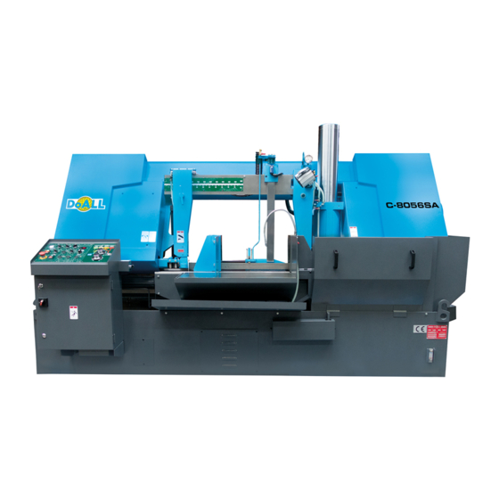
Page 1: Metal Cutting
C-8056SA Utility Line Metal Cutting Band Sawing Machine Version 20-8-2014... - Page 4 Please fill in the basic information in the spaces below: (1) MACHINE MODEL: ____________________ (2) SERIAL NUMBER: ____________________ (3) SHIPPING DATE: ____________________ (4) OTHERS: ____________________ MODEL ITEMS C-8056SA SAW BLADE 6800 × 54 × 1,6mm MAIN DRIVE BELT 3V530X2 STEEL BRUSH BELT...
-
Page 5: Table Of Contents
CONTENTS 1. SAFETY RULES ..............6 2. MACHINE SPECIFICATIONS ..........7 3. USER'S PREPARATION ............9 4. MOVING AND INSTALLING THE MACHINE ....... 11 5. OPERATION INSTRUCTIONS ..........14 6. MACHINE REPAIR AND MAINTENANCE ......20 7. TROUBLE SHOOTING ............25 8. -
Page 6: Safety Rules
1. SAFETY RULES CLOTHING To protect the operator from entangling or clamping by the machine, the operator must remove gloves and beware of loose clothing. Before operating the machine, wear safety shoes to avoid foot injury by waste material. INSTALLATION The machine must be properly grounded to avoid danger by electric shock. -
Page 7: Machine Specifications
2. MACHINE SPECIFICATIONS 2.1 SPECIFICATIONS MODEL C-8056SA ● 100 ~ 560 mm Cutting capacity 100 (W) × 100 (H) to 300 (W) × 280 (H) mm Max. 560 (W) x 270 (H) mm Bundle Cutting Min. 300 (W) x 120 (W) mm Size 6.800 x 54 x 1,6 mm... - Page 8 2.2 DIMENSIONAL DRAWINGS 2160...
-
Page 9: User's Preparation
3. USER'S PREPARATION 3.1 INSTALLATION SPACE REQUIRED When installing the machine, the installation space should be considered as the figures shown below: 1. Operator's working area 2. Workpiece collection area 3. Chip tank installation and maintenance area 4. Hydraulic unit checking area 2500... - Page 10 3.2 FOUNDATION REQUIRED The thickness should be over 200mm. The foundation work must comply with local regulations of construction. It is not suggested to install the machine in an upstairs area. 3.3 INSTALLATION ENVIRONMENT ※ Do not install the machine or controller at a location with direct sunlight and keep the machine free from pollution of chips, water or oil from other machines.
-
Page 11: Moving And Installing The Machine
4. MOVING AND INSTALLING THE MACHINE 4.1 MOVING THE MACHINE The machine and roller stand are moved separately as shown in the figure below: The figure shows the lifting positions and steel wire rope is used. C-8056SA 5 T0N HOIST CAPACITY... - Page 12 The figure shows the machine being lifted by a forklift C-8056SA 5 T0N FORKLIFT CAPACITY 4.2 INSTALLING THE MACHINE 4.2.1 Once the machine has been moved to the worksite, you need to make the machine leveling adjustment using the leveling adjustment bolts and pads. Use the bracket in front of the vise as a reference plane for leveling adjustments.
- Page 13 4.3.2 REMOVING FIX OBJECTS To avoid machine parts vibration during transportation, some objects are applied to keep the machine parts fixed. Be sure to remove all these objects before connecting the power wires. Otherwise, machine damage may occur once the power is turned on. 4.3.3 Before connecting power wires, make sure the machine voltage is in compliance with that of your factory power source.
-
Page 14: Operation Instructions
5. OPERATION INSTRUCTIONS 5.1 CONTROL PANEL 1. POWER LAMP When the power switch is turned on, this power lamp lights up. 2. WORKING LIGHT SWITCH Switch to right for turning on the light. Switch to left for turning off the light. 3. - Page 15 7. EMERGENCY STOP SWITCH When this switch is pressed, the control power is turned off. 8. BLADE START/STOP SWITCH When the clamping indication lamp for the table lights up, press the upper switch for starting the saw blade. Press the lower switch for stopping the saw blade. 9.
- Page 16 (8) Have the back side of the blade come into contact with the saw wheel edge. (9) Shift the tension lever to position to tighten the blade tension. (10) Adjust the steel brush position so that it just touches the gullet of blade tooth. 5.2.2 ADJUSTING SAW ARM POSITION The saw arm position should be properly adjusted according to the workpiece width.
- Page 17 5.4 NOTICES FOR OPERATION (1) The "EMERGENCY STOP" should be used at a proper time. Except for an emergent damage to the machine or operator occurs, normally stopping the machine by pressing the SAW ARM RAISE SWITCH is suggested. During cutting, when the "EMERGENCY STOP" button is pressed, the power will be shut off immediately.
- Page 18 TYPE BUNDLE SINGLE (SOLID) SINGLE (PIPE) BUNDLE (PIPE) (SOLID) Thickness under Single thickness 4 mm under 4 mm Thickness 4~10 Single thickness 4~8 Under 80 mm Single piece 20 Thickness over Single thickness 60~150 mm 15 mm 8~15 mm Single piece 25 Thickness over Single thickness over 150~250 mm...
- Page 19 STEEL MATERIAL CUTTING DATA CODE BLADE CUTTING AISI SPEED RATE M/MIN /MIN DESCRIPTION SS41 A570 St44-2 60~70 50~60 Low Carbon Steel S10C 1010 75~80 55~65 S15C 1015 75~80 55~65 S45C 1045 50~60 40~50 Mild Carbon Steel S55C 1055 CK55 50~60 40~50 Cr Mo Steel SCM440...
-
Page 20: Machine Repair And Maintenance
6 MACHINE REPAIR AND MAINTENANCE 6.1 QUALIFICATION OF MACHINE PERSONNEL MACHINE MAINTENANCE PERSONNEL: The person must have enough knowledge of machinery and have been well trained. ELECTRIC MAINTENANCE PERSONNEL: The person must have enough knowledge of electronics and have been well trained. 6.2 MACHINE REPAIR During operation, the machine may suffer from damage caused by personnel or other factors. - Page 21 1. Replace the oil in spindle gearbox. (Replace oil after initial 3 months, then, every 6 months) ※Suggested gear oil: SAE 90 (ISO 220) EVERY THREE MONTHS 2. Check all lock screws. Tighten them if necessary. 3. Check main drive belt tension. 4.
- Page 22 6.4 LUBRICATION GREASE NIPPLE TENSIONING UNIT...
- Page 23 GREASE NIPPLE DRIVEN WHEEL GREASE NIPPLE SIDE GUARD OF GEAR BOX...
- Page 24 GREASE NIPPLE WORM BEARING IN GEARBOX...
-
Page 25: Trouble Shooting
7. MACHINE TROUBLE SHOOTING During operation, the machine may fail in operation due to personal or other factors. At this time, the trouble must be solved as shown below: SA Series ERROR MESSAGE CORRECTION 1. Release the EMERGENCY STOP Hydraulic system does not start 2. -
Page 26: Hydraulic Circuit Diagram
8. HYDRAULIC CIRCUIT DIAGRAM...
Need help?
Do you have a question about the C-8056SA and is the answer not in the manual?
Questions and answers