
Related Manuals for Sensaphone Sentinel Pro


Summary of Contents for Sensaphone Sentinel Pro
- Page 1 CLOUD BASED MONITORING InstallatIon and setup guIde VersIon 3.2 SENSAPHONE ® REMOTE MONITORING SOLUTIONS...
- Page 2 Every effort has been made to ensure that the information in this document is complete, accurate and up-to-date. Sensaphone assumes no responsibility for the results of errors beyond its control. Sensaphone also cannot guarantee that changes in equipment made by other manufacturers, and referred to in this manual, will not affect the applicability of the information in this manual.
-
Page 3: Important Safety Instructions
• Read and follow all warning and instruction labels on the product itself. • To protect the Sentinel Pro from overheating, make sure all openings on the unit are not blocked. Do not place on or near a heat source, such as a radiator or heat register. - Page 4 Sentinel Pro Installation and Setup Guide FCC requirements Part 15: This equipment has been tested and found to comply with the limits for a Class A digital device, pursuant to Part 15 of the FCC Rules. These limits are designed to provide reasonable protection against harmful interference when the equipment is operated in a commercial environment.
- Page 5 THIS LIMITED WARRANTY CONTAINS SENSAPHONE’S STANDARD TERMS AND CONDITIONS. WHERE PERMITTED BY THE APPLICABLE LAW, BY KEEPING YOUR SENSAPHONE PRODUCT BEYOND THIRTY (30) DAYS AFTER THE DATE OF DELIVERY, YOU FULLY ACCEPT THE TERMS AND CONDITIONS SET FORTH IN THIS LIMITED WARRANTY.
- Page 6 Sentinel Pro Installation and Setup Guide PARTICULAR PURPOSE AND THE WARRANTY OF NON-INFRINGEMENT AND/OR ANY WARRANTY ARISING FROM A COURSE OF DEALING, USAGE, OR TRADE PRACTICE. IT MUST BE CLEAR THAT THE WARRANTORS ARE NOT INSURING YOUR PREMISES OR BUSINESS OR GUARANTEEING THAT THERE WILL NOT BE DAMAGE TO YOUR PERSON OR PROPERTY OR BUSINESS IF YOU USE THIS PRODUCT.
-
Page 7: Table Of Contents
The SenTInel Pro To FaCTory DeFaulT SeTTInGS . . . . . . . . . . . . . . . . - Page 8 Sentinel Pro Installation and Setup Guide manaGe uSer GrouPS . . . . . . . . . . . . . . . . . . . . . . . . . . . . . . . . . . . . . . . . . . . . . . . . . . . . . . . . . . . . . . . . . .25 alarm DelIvery .
-
Page 9: Chapter 1: Installation
Monitored conditions can include temperature, humidity levels, pressure, flow, leak detection, UPS systems, and more. The Sentinel Pro allows you to read up to 64 Modbus registers from third party equipment so that you can create alarms, view the values over the internet, and record the values for trending purposes. -
Page 10: About This Manual
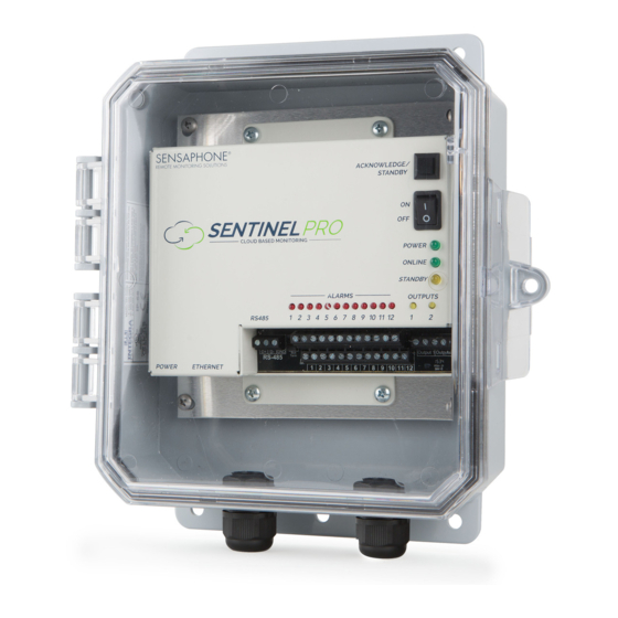
InsTallaTIon and ConfIGuraTIon physICal desCrIptIon The Sentinel Pro is housed in a 6.8” x 6.3” x 1.5” enclosure, which can be easily mounted on a wall or back panel. layout The Sentinel Pro has connections for twelve sensor inputs, two relay outputs, an Ethernet port, and 12VDC power. -
Page 11: Online Led (Green)
Power: 115VAC 50/60 Hz outlet within 6’ poWer Connect the included DC power supply to the power jack on the Sentinel Pro. Plug the power adapter into a 115V AC power outlet. netWork ConFIguratIon The Sentinel requires an Internet connection to operate. Using the included network cable, connect the Sentinel to your 10/100 network hub, switch, or router. -
Page 12: Wall Mount Installation
Sentinel Pro Installation and Setup Guide Wall Mount InstallatIon The Sentinel Pro can be wall mounted using dry wall anchors and (4) #8 screws. Follow the steps below: 1) Install four drywall anchors (if necessary). Attach the Sentinel Pro using four #8 tapping screws. See Figure 2 for dimensions. -
Page 13: Connecting Sensors
2.8K and 10K temperature sensors, and 4–20mA current sources. Compatible sensors and accessories are shown on the Sentinel Pro website. Sensors may be connected while the device is pow- ered on or off. A proper size screwdriver is provided for your convenience. Contact Sensaphone or your Sensaphone reseller for assistance in selecting sensors for your monitoring requirements. -
Page 14: Normally Open / Normally Closed Dry Contacts
Wiring a Dry Contact Sensor 2.8k/10k teMperature sensors The Sentinel Pro is compatible with 2.8K/10K temperature sensors that match the curve data listed in the tables in Appendix D. The monitoring temperature range of the 2.8K thermistor is -109 to 115ºF (-85º... -
Page 15: Relay Output Wiring
WIrIng The Sentinel Pro includes two relay outputs (switches) that can be used to turn on a light, siren, or other device whenever an alarm occurs. The output are normally–open (i.e. off) dry contacts that can be used for low voltage switching. -
Page 16: Battery Backup
FaCtory deFault settIngs In the event that you can no longer connect to your Sentinel Pro, you can reset the unit to factory defaults. On the bottom of the unit is a small hole. Beneath the hole is a push button. Insert a paper clip or similar item into the hole and push the button for 5 seconds while the device is powered on. -
Page 17: Chapter 2: Set Up
2. Fill in the form to create a new account. 3. Once you are logged in, click Admin, then Manage Devices. In the “Add a Device” section, enter the Serial Number of your Sentinel Pro and enter a device name. Click the Add Device button when fin- ished. - Page 18 Standby mode. You can also exit Standby mode using the same methods. Standby – Allows you to put the selected devices into Standby mode Enter – Put the Sentinel Pro in Standby mode for the length of time that is set on the Device Configure page Enter (Untimed) –...
-
Page 19: Device Details
Power, Battery and Relay Outputs. As you select an option, the form on the right will change to display the appropriate data. Complete the address so that the Sentinel Pro icon will be displayed at the appropriate location on the dashboard map. - Page 20 Sentinel Pro Installation and Setup Guide This page also contains settings for the Device Offline alarm and for Standby Mode. The Device Offline alarm will notify you if your devices stops communicating with the sensaphone.net servers for the pro- grammed time duration.
-
Page 21: Zone Parameter Definitions
Chapter 2: set up Zone programming Select the zone you would like to configure from the box from the left. A sample screen for a tempera- ture sensor is shown below. Zone paraMeter deFInItIons Enable/Disable: This setting determines if the Zone is being used (Enabled) or not (Disabled). Selecting Disabled will remove the gauge from the Summary screen. - Page 22 Alarm Reset Time: This is the time allowed for an alarm’s fault condition to be corrected before the Sentinel Pro resets (reactivates) the alarm and begins the message delivery process all over again. It is recommended that this be set to no lower than 30 minutes to prevent numerous messages from being sent.
-
Page 23: Manage Users
Chapter 2: set up Manage users The sensaphone.net website allows you to set up users that will be linked to your account. Each user can be configured to have their own login for website access and/or be contacted for alarms. In addition, you can choose to give alarm acknowledgement capability to each user. - Page 24 Sentinel Pro Installation and Setup Guide or Cellular subscription. Email alarm delivery is free}. A ‘1’ in the beginning of the telephone number is not required. To add additional contacts click “Add Contact”. Be sure to add all of your possible contact methods in this section.
-
Page 25: Manage User Groups
Chapter 2: set up Manage user groups Allows you to set up groups of users that can be used on other site pages. Select the group you wish to edit from the dropdown menu, or select Create New Group to make a new group. -
Page 26: Logs
“Ack”. logs The Sentinel Pro includes an Alarm Log and Data Log. The Alarm Log lists all alarm activity for the selected device. You can narrow down the messages by individual zones or you can select multiple zones. -
Page 27: Device Management
Chapter 2: set up also an option to Save the data to a file. To get to the Device Logs section, click the Details button from the Dashboard for the device you would like to view, then click the Device Logs button. Alarm Log –... -
Page 28: Device Groups
Sentinel Pro Installation and Setup Guide deVICe groups In cases where you have many devices and many users it may be desirable to create Device Groups. These can make it easier to assign device permissions to specified Users. From the main menu select Admin, then Device Groups. -
Page 29: Chapter 3: Configuring The Relay Outputs
ChapTer 3: ConfIGurInG The relay ouTpuTs The Sentinel Pro includes two relay outputs that can be used to control a light, siren, or other low voltage device. The output can be configured to switch either manually or automatically when a zone changes state or exceeds the alarm limits. -
Page 30: Relay Output Wiring
Sentinel Pro Installation and Setup Guide Action - This setting determines what the Output will do when the selected zone (or zones) exceeds the alarm limits. You can have the relay Activate (turn-on), Deactivate (turn-off), or Cycle (ON under nor- mal conditions, momentarily OFF for 10 seconds when an alarm condition occurs, then back ON). -
Page 31: Chapter 4: Modbus
ChaPTer 4: moDBuS ChapTer 4: Modbus The Sentinel Pro can be configured to read up to 64 Modbus registers from any modbus device so that you can create alarms, view the values over the internet, and record the values for trending purposes. - Page 32 Sentinel Pro Installation and Setup Guide To query data from a network-based Modbus device using ModbusTCP, go to the Configure Device page and scroll down to the Modbus TCP Settings section. Set the Mode to Master, then click Save Changes.
-
Page 33: Modbus Zone Setup
Attention to detail is vital when setting up a modbus zone. If any of the below settings are not correct, the Sentinel Pro will fail to retrieve the data from the slave device or will read incorrect values. If you are unsure of the correct setting, refer to the user’s manual for the device you are trying to connect to. - Page 34 Register Size: Specifies the size (in bits) of each register that the slave device is sending to your Sentinel Pro. A register size of 16 bits is the de- facto standard however the Sentinel Pro will also support registers of 8 and...
-
Page 35: Connecting Modbus Rs-485 Devices To Your Sentinel Pro
32 devices on the same network. This is not a hard limit and varies based upon the load applied to the Sentinel Pro by the third party devices and how well the physical network is set up. - Page 36 Sentinel Pro Installation and Setup Guide suggested Cable type: The table below gives suggested specifications for the cable used to connect the Sentinel Pro to other Modbus RS-485 devices. The closer the cable you choose matches these specs, the more likely it is that your Sentinel Pro will be able to communicate to other modbus devices without error.
-
Page 37: Appendix A: Weekly Testing Procedure
AC adapter after the unit has finished. 4.) Keep a log of your tests, noting the date and whether the Sentinel Pro passed in each category tested. An example of such a log is shown below. (See “Test Log” at the end of this manual.) -
Page 38: Appendix B: Accessories
Sentinel Pro Installation and Setup Guide appendIx b: aCCessorIes The sensors listed below are available from Sensaphone, and represent the most commonly used zone devices. Other dry contact sensors, designed for more specialized applications, may also be used. Commercial or industrial electrical supply houses can provide devices to monitor virtually any condi- tion. -
Page 39: Appendix C: Specifications
appendix C: Specifications appendIx C: speCIfICaTIons alert Zones Number of Zones: 12 Zone Connector: terminal block Zone Types: N.O./N.C. contact, 2.8K Thermistor ( -109° to 115ºF, -85º to 57ºC ) And 10K Thermistor (-87° to 168°F; -66° to 76°C), and 4-20mA (-80,000.0 to 80,000.0 Zone Characteristics: 28.7KΩ... -
Page 40: Environmental
Sentinel Pro Installation and Setup Guide enVIronMental Operating Temperature: 32–122° F (0–50° C) Operating Humidity: 0–90% RH non-condensing Storage Temperature: 32°–140° F (0–60° C) physICal Dimensions: 5.5” x 5.5” x 1.5” (14 cm x 14 cm x 3.8 cm) Weight: 1.5 lbs. (680 grams) -
Page 41: Appendix D: Thermistors
appendix D: Thermistors appendIx d: TherMIsTors 2.8k therMIstor data Degrees Celsius Resistance (Ohms) 187,625 94,206 49,549 27,180 15,491 9,142 5,572 3,498 2,256 1,491 1,009 10k therMIstor data Degrees Celsius Resistance (Ohms) 441.3K 239.8K 135.2K 78.91K 47.54K 29.49K 18.79K 12.25K 8,194K 5,592 3,893 2,760... -
Page 42: Appendix E: Returning The Unit For Repair
The unIT for repaIr In the event that the Sentinel Pro does not function properly, we suggest that you do the following: 1) Record your observations regarding the Sentinel Pro’s malfunction. 2) Call the Technical Service Department at 610-558-2700 prior to sending the unit to Sensaphone for repair. -
Page 43: Appendix F: Test Log
appendix F: Test log appendIx f: TesT loG Alarms... - Page 44 Sentinel Pro Installation and Setup Guide...
Need help?
Do you have a question about the Sentinel Pro and is the answer not in the manual?
Questions and answers
How do you add users?
To add users to Sensaphone Sentinel Pro:
1. Go to the "Manage Users" page.
2. Add alarm users to your account.
3. To group users, go to the "Manage user groups" section.
4. Select an existing group or click "Create New Group."
5. Give the group a unique, descriptive name.
6. Click the plus icon to add users from the list of alarm users.
7. You can add an entire user or select individual destinations.
8. Click the red X icon to remove users if needed.
9. Click "Save Group" when finished.
This answer is automatically generated