
Related Manuals for Raymarine EV-100


Summary of Contents for Raymarine EV-100
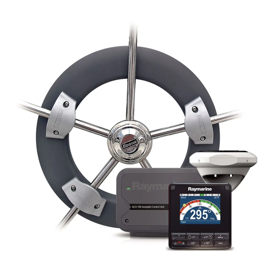
- Page 1 Evolution Wheel drive autopilot Installation Instructions English Date: 05-2017 Document number: 87287-2 © 2017 Raymarine UK Limited...
- Page 3 Raymarine product. To get the best from the product, please read this handbook thoroughly. Warranty To register your new Raymarine product, please take a few minutes to register on the website at www.raymarine.com/warranty Safety notices...
- Page 4 Your Raymarine autopilot will add a new dimension to your boating enjoyment. However, it is the skipper’s responsibility to ensure the safety of the boat at all times by following these basic rules: • Ensure that someone is present at the helm AT ALL TIMES, to take manual control in an emergency.
-
Page 5: Emc Installation Guidelines
EMC installation guidelines All Raymarine equipment and accessories are designed to the best industry standards for use in the recreational marine environment. Their design and manufacture conforms to the appropriate Electromagnetic Compatibility (EMC) standards, but correct installation is required to ensure that performance is not compromised. - Page 7 Parts supplied Pedestal bracket 16 mm spoke 12 mm spoke Wheel drive parts clamp insert (x3) clamp insert (x3) Wheel drive Clamp screw, Bracket screw, Spoke clamp (x3) M5 x 16 mm (x6) No 10 x 3/4 in (x4) 6 mm 4 mm drill bit drill bit...
- Page 8 Dimensions Wheel drive dimensions 28 mm (1.1 in) 228 mm (9.0 in) diameter 135 mm (5.3 in) 152 mm (6.0 in) 154 mm (6.1 in) motor tube: 171 mm (6.7 in) 48 mm (1.9 in) 361 mm (14.2 in) diameter [plus 60 mm (2.4 in) diameter for cable clearance]...
- Page 9 Wheel drive (wheel pilots only) The Raymarine wheel drive will fit 3, 4, 5, 6, 7 or 8 spoke wheels. It is designed to operate with steering systems with between 1 to 3.5 turns lock to lock. Clamp screw, Wheel drive...
- Page 10 Drilling the spoke clamp holes 1. Remove the wheel drive front cover: • the front cover is held onto the wheel drive by three ‘push-fit’ posts which sit in three sockets on the drive ring • to remove the cover, hold the motor in one hand and use your other hand to pull the cover up and away from the drive unit (as shown below) D5403-1...
- Page 11 Note: The wheel drive is designed to work with 3 spoke clamps on 4 or 8 spoke wheels. For cosmetic reasons, however, you may want to fit an extra spoke clamp to the fourth spoke. Raymarine dealers can supply an extra spoke clamp (part number A18089).
- Page 12 4. Align the cover with the wheel drive: • the two pre-drilled holes (marked with an arrow) must line up with their matching pair of threaded inserts on the drive ring (also marked with an arrow) • make sure that the other spoke clamp holes align with their threaded inserts Note: The cover will only fit back onto the wheel drive when you have aligned the two parts correctly.
- Page 13 Securing the wheel drive to the wheel 1. Remove the wheel from the pedestal and place it on top of the drive unit, with the front of the wheel and drive both facing up. 2. Using the wheel drive template at the end of this book, select the correct set of spoke clamp inserts for your wheel: •...
- Page 14 Note: If your wheel is bulkhead or box pedestal mounted, you will need to obtain a bulkhead fitting kit (part number E15017) from your Raymarine dealer. Fitting instructions are supplied with the kit. Motor tube location Depending on the design of your pedestal and any surrounding obstructions, you can mount the wheel drive in one of two ways: •...
- Page 15 Pedestal bracket – length and position Note: If you are replacing an existing wheel drive, you need to: remove the old pedestal bracket, cut the new bracket pin to the correct length (see steps 2 and 3 below), then secure it in the standard orientation using the existing pedestal holes.
- Page 16 Note: You can install the pedestal bracket either way up. In the standard orientation the pin is at the bottom (below the mounting holes – see diagram). If obstructions on the pedestal prevent you from using the standard orientation, you can install the bracket so the pin is at the top (above the mounting holes).
- Page 17 154 mm (6.1 in) D5346-2 8. When the pedestal bracket is correctly positioned and aligned, mark around the inside of the slots, then remove the bracket. 9. Use a center-punch to mark the center of each slot, then use the smaller supplied drill bit to drill a 4.0 mm ( in) diameter hole.
- Page 18 Note: If the wheel is bent or the wheel drive is off center, the pin will move up and down in the back plate slot. As long as the pin does not hit the top or bottom of the slot, this pin movement will not affect the drive unit’s performance.
- Page 19 2. Route the cable through the pedestal (or guard rail) and back to the control unit: • if the pedestal has a cable duct, use this for the drive cable to make sure that it cannot foul the steering mechanism D5338-1 3.
- Page 20 ACU (control unit) connection Wheel Drive cable MOTOR POWER Blue Brown To the D13589-1 NOTE: You can use the autopilot control head to change the Motor phase: MENU > Setup > Autopilot Calibration > Drive Settings > Motor Phasing...
- Page 21 Rudder position sensor (wheel pilot) NOTE: Not all systems are supplied with a rudder sensor. It is available separately as part number M81105. The rudder position sensor connects directly to the boat’s tiller arm or quadrant. Installing the sensor involves five main steps: •...
- Page 22 Front view - rudder amidships Ball joints (level) Connecting rod Sensor arm Parallel Rudder position sensor Tiller arm Mounting base or quadrant Top view - rudder amidships Parallel Cable entry 60˚ 60˚ Maximum 90˚ permitted travel: +/- 60˚ Minimum: 75 mm (3 in) Maximum: 310 mm (12 in) D5387-1 Horizontal alignment...
- Page 23 Securing the sensor to the boat Location Mount the rudder position sensor on a suitable base alongside the rudder stock and tiller arm. Note: If necessary, you can install the sensor upside down. If you mount the sensor in this way, you must swap the red and green cable connections at the control unit.
- Page 24 Attaching the connector rod 1. Use a hacksaw to cut the threaded connector rod to length. 2. Screw the lock nuts onto the road and then the ball-pin sockets. 3. Press the sockets onto the pins on the sensor arm and tiller pin. Note: To give the precise rudder position, the rudder sensor has a built-in spring to remove any free play in the linkage to the tiller.
- Page 25 Setting-up the system When you have installed the system, you need to check that the system is wired correctly and set up to suit your type of boat. This chapter provide instructions for the following post-installation procedures: Functional test Switch on 1.
- Page 26 Autopilot steering direction The autopilot steering direction defines which way the autopilot applies helm when you press a course change key or when the boat goes off course. Check the autopilot steering direction as follows: 1. Wheel Pilot: Engage the wheel drive clutch by rotating the clutch lever clockwise so it engages fully onto the locating pip.
- Page 27 6.2 Check rudder sensor operation (if fitted) Note: This procedure is only required if you have fitted a rudder position sensor to a wheel pilot system. If you have fitted a rudder position sensor to a wheel pilot, before commencing the initial sea trial you must make sure that it senses rudder movement in the correct way and is aligned with the rudder: 1.
- Page 28 Initial sea trial When you have checked that the system is functioning correctly, you must complete the setup by taking the boat on a short sea trial to: • correct the compass deviation • adjust the heading alignment • check autopilot operation •...
- Page 29 2.2 Using Auto mode Engaging the autopilot (Auto mode) 1. Steady the boat on the required heading. 2. Wheel Pilot: Engage the wheel drive clutch by rotating the clutch lever clockwise (so the lever engages fully onto the locating pip). WARNING: Wheel drive clutch Always reach AROUND (not through) the wheel to operate the wheel drive clutch lever.
- Page 30 CAUTION: Autopilot course control makes it easier to sail a boat, but it is NOT a substitute for good seamanship. ALWAYS maintain a permanent watch, no matter how clear the sea appears to be. Disengaging the autopilot (Standby mode) 1. Press standby. •...
-
Page 31: Fault Finding
Fault finding All Raymarine products are designed to provide many years of trouble-free operation. We also put them through comprehensive testing and quality assurance procedures before shipping. In the unlikely event that a fault does occur with your autopilot, use the following table to help identify the problem and provide a solution. - Page 32 SYMPTOM SOLUTION Cabling problem – make sure all the cables are The autopilot will not ‘talk’ to other connected properly. SeaTalk instruments Navigator not transmitting the correct position Position information not received data. No bearing to waypoint information received The autopilot will not auto advance to from the navigator.
- Page 33 Cleaning the wheel drive CAUTION: Do not use mineral-based solvents (such as WD40) to lubricate or clean the wheel drive as they will damage the material. We recommend that you complete the following steps each season to prevent the build-up of salt on the wheel drive bearings and drive belt: 1.
- Page 34 (if it is broken, frayed or stretched), you should replace the drive belt. You can obtain a replacement belt from any Raymarine dealer (part number A18083). Fitting instructions are supplied with the belt. User serviceable parts...
-
Page 35: Control Unit
• To minimize these effects and enable you to get the best possible performance from your Raymarine equipment, guidelines are given in the installation instructions, to enable you to ensure... -
Page 36: Product Support
Electromagnetic Compatibility (EMC). • Always report any EMC-related problems to your nearest Raymarine dealer. We use such information to improve our quality standards. • In some installations, it may not be possible to prevent the equipment from being affected by external influences. - Page 38 User notes...
- Page 39 User notes...
- Page 40 www.raymarine.com...
Need help?
Do you have a question about the EV-100 and is the answer not in the manual?
Questions and answers