
Related Manuals for Owandy I-Max Touch


Summary of Contents for Owandy I-Max Touch
- Page 1 I-Max Touch 0459 (110-120V version) User's Manual Version 25 September 2009 (Rev. 0)
-
Page 2: Table Of Contents
6.2 Digital Sensor ..................37 6.2.1 Inserting the sensor in the sensor holder........38 6.2.2 Release of the sensor from the sensor holder ......39 6.3 Switching on the device ................ 40 6.4 Positioning of chin support ..............42 (Rev. 0) I-Max Touch (110-120V) - Page 3 Preparation of the patient ............95 6.9.3 Making an exposure ..............96 6.10 Messages on display ................98 6.10.1 Error message with error code E000 ÷ E199 ......99 6.10.2 Error message with error code E200 ÷ E299 ......99 I-Max Touch (110-120V) (Rev. 0)
- Page 4 6.13 Storing of automatical exposure parameters ........120 6.13.1 Table of pre-set anatomic parameters........121 MAINTENANCE No part of this publication can be reproduced, transmitted, transcribed or translated without the approval of Owandy. This manual in English is the original version. (Rev. 0) I-Max Touch (110-120V)
- Page 5 USER'S MANUAL Contents THIS PAGE IS INTENTIONALLY LEFT BLANK I-Max Touch (110-120V) (Rev. 0)
-
Page 6: Introduction
The I-Max Touch is an electro-medical device and it can be used only under the supervision of a physician or of highly qualified personnel, with the necessary knowledge on X-ray protection. -
Page 7: Icons Appearing In The Manual
This icon indicates a “NOTE”: please read the items marked by this icon thoroughly. This icon indicates a “WARNING”: the items marked by this icon refer to the safety aspects of the patient and/or the operator. I-Max Touch (110-120V) (Rev. 0) -
Page 8: Safety Information
Owandy cannot be held responsible for: • the use of the I-Max Touch different from the intended use • damage to the unit, the operator or the patient, caused both by installation and maintenance procedures different from those... -
Page 9: Warnings
While performing the radiography, no-one, apart from the operator and the patient, must remain in the room. The I-Max Touch has been built to support a continuous operation at intermittent load; therefore please follow the described use cycles to enable the device to cool down. - Page 10 Figure 1 and Figure 2. Minimum distance from X-ray source 1.5m Protected area Figure 1 - Panoramic version Minimum distance from X-ray source 1.5m Protected area Figure 2 - Cephalometric version (Rev. 0) I-Max Touch (110-120V)
- Page 11 If the PC is positioned outside the patient environment when in use, the PC has to be compliant to IEC 60950, otherwise the PC must complies with medical standard IEC 60601-1. NOTE: When the unit is switched on, do not move the rotating arm or the tube-head. I-Max Touch (110-120V) (Rev. 0)
-
Page 12: Environmental Risks And Displacement
Tube-head: dielectric oil, lead, copper, iron, aluminium, glass, tungsten. • Control Panel iron, copper, aluminium, glass-resin, non- biodegradable plastic material packaging. • Column, rotating arm and extensions: iron, lead, aluminium, copper, glass-resin, and non-biodegradable plastic material. (Rev. 0) I-Max Touch (110-120V) -
Page 13: Symbols Used
USER'S MANUAL Safety information Symbols used In this manual and on the I-Max Touch itself, apart from the symbols indicated on the control panel, the following icons are also used (see Chapter 6): Symbol Description Device with type B applied parts... -
Page 14: Cleaning And Disinfection
Thoroughly clean the chin support, resting handles, nose-rest and temple clasps group any time these are used. The chin support, resting handles, nose-rest and temple clasps group should be disinfected (when considered necessary) with a solution of 2% glutaraldehyde. (Rev. 0) I-Max Touch (110-120V) -
Page 15: Description
USER'S MANUAL Description DESCRIPTION Identification labels and laser labels 6, 7 1, 8 I-Max Touch (110-120V) (Rev. 0) - Page 16 Description I-Max Touch Tube-head identification label identification label CEPHALOMETRIC device identification label PANO PANCEPH. Digital Sensor Digital Sensor identification label identification label WARNING label (N° 2) Spot Laser identification label (N° 2) Laser symbol label (Rev. 0) I-Max Touch (110-120V)
-
Page 17: Functions, Models And Versions
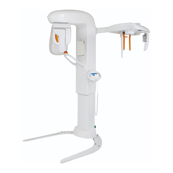
USER'S MANUAL Description Functions, models and versions The I-Max Touch, produced by Owandy, is a complete panoramic system, which enables to perform all X-rays commonly necessary in dental field (except for endoral X-rays). In some versions, certain examination modes are not available but the device (thanks to its computerised control system) can be expanded and updated with new releases, directly at the Dentist premises. -
Page 18: Version With Cephalometric Device
The values of the exposure factors shown in the tables of paragraph 6.13, set as default, are for guidance only. The real adjustment of these values depends on user’s trade off between expose dose and image contrast. Image processing should help you getting the best contrast. (Rev. 0) I-Max Touch (110-120V) -
Page 19: Technical Characteristics
6 ÷ 12 mA in 1 mA steps for Ceph (up to 76 kVp) 6 ÷ 10 mA in 1 mA steps for Ceph (from 78 kVp to 86 kVp) Sensor cover additional filtration 0.5 mm Al eq @ 70 kV I-Max Touch (110-120V) (Rev. 0) - Page 20 Cephalometry and Carpus • Normal resolution cephalometry in Latero-Lateral or Antero-Posterior projection (different formats) • High resolution cephalometry Latero- Lateral or Antero-Posterior projection (different formats) • Normal and High Resolution Carpus exam • Motorized Soft Tissue Filter. (Rev. 0) I-Max Touch (110-120V)
- Page 21 OPX 105 Nominal focus size 0.5 IEC 60336 Inherent filtration 0.5 mm Al eq. Anode tilt 5° Anode material Tungsten Nominal maximum voltage 105 kV Filament max current Filament max voltage Anode thermal capacity 30 kJ I-Max Touch (110-120V) (Rev. 0)
- Page 22 87 kg (192 lbs) Weight of arm support, rotating arm and 74 kg (163 lbs) tube head CEPH arm 25 kg (55 lbs) Legs (optional) 30 kg (66 lbs) Sensor holder weight 2 kg (5 lbs) (Rev. 0) I-Max Touch (110-120V)
- Page 23 Relative working humidity (RH) range 30% ÷ 75% Temperature range for transport and - 20° ÷ + 70° storing Humidity range for transport and < 95% without condense storing Minimum atmospheric pressure for 630 hPa transport and storing I-Max Touch (110-120V) (Rev. 0)
-
Page 24: Dimensions
USER'S MANUAL Technical characteristics Dimensions 1009 (39,74") Ø 1040 (40,95") Ø 1140 (44,88") with free standing base Figure 3 – I-Max Touch dimensions Base version (Rev. 0) I-Max Touch (110-120V) - Page 25 USER'S MANUAL Technical characteristics 1009 (39,74") Ø 1040 (40,95") Ø 1140 (44,88") with free standing base 1910 (75,20") 1970 (77,56") with free standing base Figure 4 – I-Max Touch dimensions Version equipped with cephalometric unit I-Max Touch (110-120V) (Rev. 0)
-
Page 26: Loading Curve Of The Tube And Cooling Curve Of The Anode
USER'S MANUAL Technical characteristics Loading curve of the tube and cooling curve of the anode Tube "CEI - OPX/105" (0.5 IEC 60336) Load Anode cooling curve (Rev. 0) I-Max Touch (110-120V) - Page 27 USER'S MANUAL Technical characteristics Tube-head heating and cooling curve I-Max Touch (110-120V) (Rev. 0)
-
Page 28: Applied Safety Regulations
IEC 60601-1-3:1994 IEC 60825-1:1993 + A1:1997 + A2:2001 Classification I-Max Touch is an electro-medical X-ray device belonging to Class 1 and Type B as per classification IEC 60601-1, foreseen for a continuous working at intermittent load. According to CE 93/42 directive for medical devices, the equipment belongs to class II B. -
Page 29: Note On Constant Magnification For Panoramic And Tmj (Mouth Open/Closed) Examinations
Note on constant magnification for Panoramic and TMJ (mouth open/closed) examinations NOTE: The I-Max Touch is based on a standard dentition and ascending rami shape. This shape, based on statistical studies, establishes a form for the dentomaxillofacial complex, adopted as "standard". -
Page 30: Measurement Method Of Technical Factors (Paragraph For Authorised Personnel)
IEC 60601-1. In particular, in accordance with IEC 60601-2-7, the maximum deviation (including the correction and instrumental doubt) is less than or equal to ±10 for kV, while for tube current it is less than or equal to ±15%. (Rev. 0) I-Max Touch (110-120V) -
Page 31: Verification Method Of Technical Factors (Paragraph For Authorised Personnel)
NOTE: This program allows you to carry out the measuring of the exposure parameters with the tube-head arm in a fixed position (not rotating) without variation due to spine compensation. 2. Place the measuring instrument. I-Max Touch (110-120V) (Rev. 0) - Page 32 5. To end the control program, press any key other than the increase and decrease keys ; the display will indicate: A N O R A M I and the unit will return to standard mode. (Rev. 0) I-Max Touch (110-120V)
-
Page 33: General Instructions For Use
GENERAL INSTRUCTIONS FOR USE Control panel - description and functions The I-Max Touch keyboard is divided into function areas, plus a display to view the operative messages and error signals. The next figure shows a general view of the control interface, while details on each functional area are provided in the following pages. - Page 34 "Zoom in" button Acquired image Figure 6 WARNING: The USB port on the keyboard MUST NOT be used with an external Hard Disk with own mains connection. It has to be used only with USB Pen Drives. (Rev. 0) I-Max Touch (110-120V)
- Page 35 Protruded protruded, standard or retracted, as indicated within the button. Standard The arch selection does not influence the values of kV and mA but acts on the position of the focus layer. Retracted I-Max Touch (110-120V) (Rev. 0)
- Page 36 ON/OFF the laser centring devices that allow the correct positioning of the medial-sagittal and Frankfurt planes, by adapting the I-Max Touch to the patient's anatomy. The key "Test" is used to avoid the Test OFF X-rays emission, in order to check the absence of collisions with the patient.
- Page 37 When the acquired image is displayed on the control panel screen, it is Zoom in possible to zoom in and out of the image using these two keys. Zoom out I-Max Touch (110-120V) (Rev. 0)
-
Page 38: Key Function Description
> Repositioning the rotation group (to bring the Other group to the initial position after the examination 17 - Display acquired image key and to exit from the "making an exposure") 18 - USB Pen Drive key mode > Confirmation (Rev. 0) I-Max Touch (110-120V) - Page 39 20 - Zoom out on the image Other 21 - Zoom in on the image 18 - USB Pen Drive key 19 - Return to control panel (main menu) USB port: to connect a pen drive I-Max Touch (110-120V) (Rev. 0)
-
Page 40: Acquired Image Display Description
Key (19) returns to the control panel, allowing for the acquisition of a new image. In the control panel, key (17) returns to the display of the acquired image. (Rev. 0) I-Max Touch (110-120V) -
Page 41: Pen Drive Function Description
Do not extract the Pen Drive from the keyboard when the Pen Drive key (18) is orange. • When the keyboard displays the acquired image, pressing the green Pen Drive key (18) will save the current acquired image on Pen Drive. I-Max Touch (110-120V) (Rev. 0) -
Page 42: Digital Sensor
USER'S MANUAL General instructions for use Digital Sensor The I-Max Touch is equipped with two types of digital sensors, depending on the version: • Sensor PAN: it is a sensor suitable for Panoramic-type imaging, i.e. all images with a 14 cm-high field; all Panoramic, TMJ, and Sinus images belong to this type. -
Page 43: Inserting The Sensor In The Sensor Holder
5. Only at this point, release the hooking lever, checking that the sensor is correctly engaged before releasing the handgrip. WARNING: During the lever releasing operation, hold the sensor firmly, to prevent the sensor from falling during the insertion phase due to possible errors. I-Max Touch (110-120V) (Rev. 0) -
Page 44: Release Of The Sensor From The Sensor Holder
4. Always gripping firmly the sensor, in order to avoid accidental falls, it is possible to freely move the sensor to the desired position. (Rev. 0) I-Max Touch (110-120V) -
Page 45: Switching On The Device
T E S T < NOTE: During this phase, the I-Max Touch does not perform any movement, it just performs a series of checks which, in the event of negative result, could require the intervention of the technician. The only problem that can be solved by the user is related to the position of the PAN sensor holder;... - Page 46 (for instance): A N O R A M I THE MACHINE IS READY NOTE: The above mentioned position is chosen also in the event that, for any reason, the device repeats the initialisation phase. (Rev. 0) I-Max Touch (110-120V)
-
Page 47: Positioning Of Chin Support
USER'S MANUAL General instructions for use Positioning of chin support The I-Max Touch is equipped with two types of supports: a standard support fitted with a special removable appendix for edentulous patients, and a lower one, for SINUS/TMJ examinations. The standard chin support must be used, in Panoramic mode, with all the people who can assure a tight grip on the centring bite. -
Page 48: Panoramic Examination
The latter is held in place, during the examination phase, by means of temple clasps rods and of a forehead support. A fourth fixing point is determined by the chin support. (Rev. 0) I-Max Touch (110-120V) -
Page 49: Preparation Of The Device
STD Panoramic -> Right Emi-panoramic -> Left Emi-panoramic -> Reduced dose Panoramic -> Improved orthogonality dentition -> Frontal dentition -> STD Panoramic. This selection is cyclic, so pressing the button repeatedly will change the selected mode. I-Max Touch (110-120V) (Rev. 0) - Page 50 As a consequence of the different trajectory, the focus layer, mainly in the front teeth area, is smaller and the patient positioning for this examination needs more care. Follow the instructions for normal Panoramic for patient positioning. (Rev. 0) I-Max Touch (110-120V)
- Page 51 Follow the instructions for normal Panoramic for patient positioning. NOTE: The I-Max Touch is based on a standard dentition and ascending rami shape. This shape, based on statistic study, establishes a form for the dentomaxillofacial complex that it is assumed as "standard".
-
Page 52: Anatomic / Manual Exposure
"M" to indicate the manual mode; it is possible to press key (7) to change from Adult to Child and press key (9) to modify the type of biting from Normal to Protruded to Retracted. (Rev. 0) I-Max Touch (110-120V) -
Page 53: Anatomic Exposure
Select the type of biting with the key "Type of Biting Selection" NOTE: The type of biting does not affect the kV and mA values, but it affects the position of the focus layer, by adapting the rotation movement to the patient's anatomy. I-Max Touch (110-120V) (Rev. 0) -
Page 54: Manual Exposure
The value of mA can vary between 6 and 10 mA, with 1 mA steps. NOTE: To change the values rapidly, keep the increase key (3) or decrease key (4) pressed. Select the type of mouth with the key "Type of Biting Selection" (Rev. 0) I-Max Touch (110-120V) - Page 55 Legend positioning devices and patient centring Panoramic chin rest Centring bite Temple clasps - Forehead support Temple clasps - Forehead support release knobs Figure 9 Figure 10 Legend of Reference Lines Sagittal medial line Frankfurt plane line I-Max Touch (110-120V) (Rev. 0)
-
Page 56: Preparation Of The Patient
The laser centring device will stay lit up until the "Centring devices ON" (14) key or, at the end of the alignment, the key "Patient Entrance" (6) is pressed to start the exposure preparation phase. (Rev. 0) I-Max Touch (110-120V) - Page 57 X-ray button once more will start the radiation phase. 10. Ask the patient to: keep the lips closed, bring the tongue towards the palate, keep perfectly still and do not look at the rotating arm during the movements. I-Max Touch (110-120V) (Rev. 0)
-
Page 58: Making An Exposure
R A Y < x = value defined by the settings NOTE: If the machine is in the "Test" mode, the display will show: T E S X R A Y N O T A C T I (Rev. 0) I-Max Touch (110-120V) - Page 59 USER'S MANUAL General instructions for use NOTE: The I-Max Touch assumes that the digital sensor is ready: if this is not the case, the following error message will be displayed: T A L E N S N O T A D Y Refer to the Manual of the Digital Acquisition System to correct the situation.
- Page 60 E T T I R E S > < and then: W A I M A C H E T T The system now returns to its initial position and the patient must be repositioned. (Rev. 0) I-Max Touch (110-120V)
- Page 61 IEC 60601-1. In particular, in accordance with IEC 60601-2-7, the maximum deviation (including the correction according to the above curve and instrumental doubt) is within ±10% for the kV, while for the tube current it is within ± 15%. I-Max Touch (110-120V) (Rev. 0)
-
Page 62: Tmj Examination
Do not release the X-ray button during the emission interruption if not necessary. The cooling phase of the tube-head occurs at the end of all 4 exposures. In the CHILD position, exposure start is delayed by a few degrees with respect to the ADULT position. (Rev. 0) I-Max Touch (110-120V) -
Page 63: Preparation Of The Device
Once the settings have been completed, the chin support must be placed in position if it has been removed (see paragraph 6.4). NOTE: The I-Max Touch is based on a standard dentition and ascending rami shape. This shape, based on statistical data, establishes a standard shape for the dentomaxillofacial complex, defining also the position and the direction of the condyles. -
Page 64: Anatomic / Manual Exposure
MANUAL: with the possibility to vary the kV and mA values already • set. NOTE: In the manual mode, the "Anatomic/Manual mode" (13) indicator displays "M" to indicate the manual mode; it is possible to use key (7) to change from Adult to Child. (Rev. 0) I-Max Touch (110-120V) -
Page 65: Anatomic Exposure
Exposure values in TMJ examination (9.7 sec) Adult Child Examination TMJ mouth closed/open Small Medium Large Table 3 The time (9.7 sec.) refers to the sum of the four exposures (2 closed mouth exposures and 2 open mouth exposures). I-Max Touch (110-120V) (Rev. 0) -
Page 66: Manual Exposure
The kV value can vary between 60 and 86 kV, with 2 kV steps. The value of mA can vary between 6 and 10 mA, with 1 mA steps. NOTE: To change the values rapidly, keep the increase key (3) or decrease key (4) pressed. (Rev. 0) I-Max Touch (110-120V) -
Page 67: Tmj Closed Mouth
Legend of Reference Lines Sagittal medial line Frankfurt plane line Legend positioning devices and patient centring SINUS/TMJ support Temple clasps - Forehead support Temple clasps - Forehead support release knobs Figure 12 - TMJ closed mouth positioning I-Max Touch (110-120V) (Rev. 0) - Page 68 The green LED "Ready for X-ray" lights up to indicate that pressing the X-ray button once more will start the radiation phase. 9. Ask the patient to: keep the lips closed, keep perfectly still and do not look at the rotating arm during the movements. (Rev. 0) I-Max Touch (110-120V)
-
Page 69: Carrying Out The First Exposure (Mouth Closed)
R A Y < x = value defined by the settings NOTE: If the machine is in the "Test" mode, the display will show: T E S X R A Y N O T A C T I I-Max Touch (110-120V) (Rev. 0) - Page 70 USER'S MANUAL General instructions for use NOTE: The I-Max Touch assumes that the digital sensor is ready: if this is not the case, the following error message will be displayed: T A L E N S N O T R E A D Y Refer to the Manual of the Digital Acquisition System to correct the situation.
-
Page 71: Tmj Open Mouth
Legend of Reference Lines Sagittal medial line Legend positioning devices and patient centring SINUS/TMJ chin support Temple clasps - Forehead support Temple clasps - Forehead support release knobs Figure 13 - Open mouth examination positioning I-Max Touch (110-120V) (Rev. 0) - Page 72 Check that, during this phase, the patient has not changed position. 7. Advise the patient to remain perfectly still and not look at the rotating arm during the movements. (Rev. 0) I-Max Touch (110-120V)
-
Page 73: Carrying Out The Second Exposure (Mouth Open)
E X A M R E - H E A T I N G . and then (after 2 seconds), the following message will be displayed: > R A Y < x = value defined by the settings I-Max Touch (110-120V) (Rev. 0) - Page 74 L E A S W A I WARNING: After every examination, clean the chin support, the handles and the temple clasps group thoroughly. (Rev. 0) I-Max Touch (110-120V)
- Page 75 The system now returns to its initial position and the patient must be repositioned. NOTE: If the open mouth exposure is not completed, the closed mouth exposure must be repeated or the four complete pictures will not appear. I-Max Touch (110-120V) (Rev. 0)
-
Page 76: Sinus Examination
N U S x = value defined by the settings During the examination, one single rotation of the rotating arm is to be expected, with the X-rays emission limited to the interested area. (Rev. 0) I-Max Touch (110-120V) -
Page 77: Anatomic / Manual Exposure
MANUAL: with the possibility to vary the kV and mA values already • set. NOTE: In the manual mode, the "Anatomic/Manual mode" (13) indicator displays "M" to indicate the manual mode; it is possible to use key (7) to change from Adult to Child. I-Max Touch (110-120V) (Rev. 0) -
Page 78: Anatomic Exposure
Select the type of build with the Size (8) key (small - medium - large). On the basis of the selections made, the display will visualise the kV and mA settings as in the table. Exposure values in SINUS examination (9.4 sec) Adult Child Small Medium Large Table 4 (Rev. 0) I-Max Touch (110-120V) -
Page 79: Manual Exposure
The kV value can vary between 60 and 86 kV, with 2 kV steps. The value of mA can vary between 6 and 10 mA, with 1 mA steps. NOTE: To change the values rapidly, keep the increase key (3) or decrease key (4) pressed. I-Max Touch (110-120V) (Rev. 0) -
Page 80: Preparation Of The Patient
Legend of Reference Lines Sagittal medial line Frankfurt plane line Legend positioning devices and patient centring SINUS/TMJ chin support Temple clasps - Forehead support Temple clasps - Forehead support release knobs Figure 14 - SINUS positioning (Rev. 0) I-Max Touch (110-120V) - Page 81 T A R T E X A M x = value defined by the settings 9. Ask the patient to: close his mouth, remain perfectly still and not look at the rotating arm during the movement. I-Max Touch (110-120V) (Rev. 0)
-
Page 82: Making An Exposure
R A Y < x = value defined by the settings NOTE: If the machine is in the "Test" mode, the display will show: T E S X R A Y N O T A C T I (Rev. 0) I-Max Touch (110-120V) - Page 83 USER'S MANUAL General instructions for use NOTE: The I-Max Touch assumes that the digital sensor is ready: if this is not the case, the following error message will be displayed: T A L E N S N O T A D Y Refer to the Manual of the Digital Acquisition System to correct the situation.
- Page 84 M A C H E T T R E S > < and then: W A I M A C H E T T The system now returns to its initial position and the patient must be repositioned. (Rev. 0) I-Max Touch (110-120V)
-
Page 85: Cephalometric Examination
The I-Max Touch makes different kinds of exposures, according to the type of selection made: 24x22... -
Page 86: Preparation Of The Device
At the same time, the temple clasps must be closed, in order to avoid collision with the rotating arm. (Rev. 0) I-Max Touch (110-120V) - Page 87 The following message will be displayed: This message indicates the image format predefined by the system; the letter "n" after the format indicates that the execution will be in Normal Resolution. I-Max Touch (110-120V) (Rev. 0)
- Page 88 The key "Type of Biting Selection" (9) is disabled. 3. By means of the keys "Arrow right" (12) and "Arrow left" (11) select the dimensions of the image and the type of projection (see the table at the beginning of the Chapter). (Rev. 0) I-Max Touch (110-120V)
-
Page 89: Anatomic / Manual Exposure
• Filter values set (mm). NOTE: In the manual mode, the "Anatomic/Manual mode" (13) indicator displays "M" to indicate the manual mode; it is possible to use key (7) to change from Adult to Child. I-Max Touch (110-120V) (Rev. 0) -
Page 90: Anatomic Exposure
The kV and mA values will be displayed according to the selections made as per the following tables: Adult Child Small Medium Large Table 5: Latero-Lateral projection Adult Child Small Medium Large Table 6: Antero-Posterior projection (Rev. 0) I-Max Touch (110-120V) -
Page 91: Manual Exposure
The "mA" value can vary between 4 and 12 mA, with 1 mA steps. The "Soft Tissue Filter" value can vary between 6 and 10.5 cm, with 0.1 cm steps. NOTE: To change the values rapidly, keep the increase key (3) or decrease key (4) pressed. I-Max Touch (110-120V) (Rev. 0) -
Page 92: Preparation Of The Patient
If a Latero-Lateral examination is performed, position the nose rest. 5. By selecting an "asymmetric" projection, the Soft Tissues Filter (STF) will be automatically inserted. Legend Nose rest Ear centring device Pins for ear centring device Nose rest graduate scale Figure 15 (Rev. 0) I-Max Touch (110-120V) -
Page 93: Making An Exposure
E X A M R E - H E A T I N G . and then (after 2 seconds), the following message will be displayed: > R A Y < x = value defined by the settings I-Max Touch (110-120V) (Rev. 0) - Page 94 USER'S MANUAL General instructions for use NOTE: The I-Max Touch assumes that the digital sensor is ready: if this is not the case, the following error message will be displayed: T A L E N S N O T R E A D Y Refer to the Manual of the Digital Acquisition System to correct the situation.
- Page 95 Then press the "Patient Entrance" (6) key The system now returns to the position for Ceph exam and the unit starts the procedure for the new examination. NOTE: After every examination, clean the ear centring device and temple clasps group thoroughly. I-Max Touch (110-120V) (Rev. 0)
-
Page 96: Examination To Assess Bone Growth (Carpus)
Symmetric, not adjustable; it is therefore necessary to position the auricular rods and the nose-rest as for the cephalometric Antero- Posterior examination, so that these elements do not interfere with the X-ray trajectory. Refer to Figure 16. (Rev. 0) I-Max Touch (110-120V) -
Page 97: Preparation Of The Device
At the same time, the temple clasps must be closed, in order to avoid collision with the rotating arm. I-Max Touch (110-120V) (Rev. 0) - Page 98 The following message will be displayed: C A R P This message indicates the image format predefined by the system; the letter "n" after the format indicates that the execution will be in Normal Resolution. (Rev. 0) I-Max Touch (110-120V)
- Page 99 High Resolution images. 5. Regulate the exposure parameters as required, using the pre-set values or manual selection; the display will show the kV and mA settings as per the following table. Child Small Medium Large Table 7 I-Max Touch (110-120V) (Rev. 0)
-
Page 100: Preparation Of The Patient
The common radiological procedure to assess bone growth in children, suggests placing the end of the middle finger tangent to the reference line. The patient's hand and arm must form a vertical line. Figure 16 (Rev. 0) I-Max Touch (110-120V) -
Page 101: Making An Exposure
R A Y < x = value defined by the settings NOTE: The I-Max Touch assumes that the digital sensor is ready: if this is not the case, the following error message will be displayed: T A L E N S... - Page 102 The following message will be displayed: R E S > < Then press the "Patient Entrance" (6) key The system now returns to the position for the Ceph exam and the unit starts the procedure for the new examination. (Rev. 0) I-Max Touch (110-120V)
-
Page 103: Messages On Display
General instructions for use 6.10 Messages on display The I-Max Touch is fully controlled by a microprocessor which controls the programming of the emission parameters and signals the various conditions of the machine, the possible abnormalities and errors via displayed messages. -
Page 104: Error Message With Error Code E000 ÷ E199
Press the key "Patient Entrance" (6) to reset the error and to perform the axes centring operation. For all other cases, call the Technical Assistance Service. (Rev. 0) I-Max Touch (110-120V) -
Page 105: Error Message With Error Code E300 ÷ E399
6.10.3.4 E360 / E361 - X-ray button pressed during start up or axis movement Release the X-ray button if pressed; press the key "Patient Entrance" to reset the error condition. If the error does not disappear, call the Technical Assistance Service. I-Max Touch (110-120V) (Rev. 0) -
Page 106: E362 - X-Ray Button Released During Examination
TMJ). This message signals that the button was released during the examination phase; the motors are unlocked, therefore the patient can get out of the system. Repeat the system centring phase and repeat the examination. (Rev. 0) I-Max Touch (110-120V) -
Page 107: Error Message With Error Code E400 ÷ E402
E362 error, as this message is generated by the HF board, which signals a possible failure on the connection of the X-rays button with the board itself. I-Max Touch (110-120V) (Rev. 0) -
Page 108: Error Message With Error Code E850 ÷ E852
During the system movement, the keyboard is disabled, but if the key "Patient Entrance" (6) is pressed the movement is interrupted. This operation is useful in case a movement anomaly is noticed. Press the key "Patient Entrance" (6) to reset the error condition. (Rev. 0) I-Max Touch (110-120V) -
Page 109: Research And Correction Of Possible Defects In Dental X-Rays
Presence (in CEPH Panoramic chin-rest still Perform the exam again, removing examination) of a mounted. the PAN chin-rest. white area in the lower part of the image. I-Max Touch (110-120V) (Rev. 0) -
Page 110: Defects Due To Wrong Data Setting
The STF value is not correct. Refer to paragraph 6.8.3 to adjust poorly) visible in L-L the position of the "STF". projection. A symmetric image format Select an asymmetrical image was selected. format (which will enable the STF filter). (Rev. 0) I-Max Touch (110-120V) -
Page 111: Defects Due To The Device
Technical Service. 2. In the event the soft tissue of the patient is not highlighted while performing a cephalometry, in a latero-lateral, let the technician verify the adjustment of the Soft Tissue Filter. I-Max Touch (110-120V) (Rev. 0) -
Page 112: Analysis Of The Problems On The Panoramic Examinations
Anatomic structure Palatal plane Maxillary sinus Maxilla and maxillary tuberosity Temporo mandibular condyle Ascending ramus of the TMJ Coronoid process (overlap with maxilla) Mandibular canal Chin foramen Anterior nasal spine Nasal cavities Ioid bone (normally duplicated) (Rev. 0) I-Max Touch (110-120V) -
Page 113: Proper Positioning Of The Patient
If not properly extended, the spine will cause the appearing of a lower exposed area (clearer) in the front part of the image. I-Max Touch (110-120V) (Rev. 0) - Page 114 The occlusal plane is shown slightly tilted upward, the palatal plane does not overlap the apex of the upper arch and therefore allows a good view of the apex itself. (Rev. 0) I-Max Touch (110-120V)
-
Page 115: Errors Due To Poor Positioning Of Patient
If, after the correct positioning of the patient, the problem still remains, check the alignment of the centring laser lights, simply switching on the centring lights and checking their position. The sagittal medial luminous beam must hit the centre of the chin support. I-Max Touch (110-120V) (Rev. 0) - Page 116 Anterior teeth are enlarged and blurred • Figure 21 shows the result of this error. Figure 21 Possible causes: The patient it positioned too much backward. Solution: Check the patient's positioning by using luminous beams. (Rev. 0) I-Max Touch (110-120V)
- Page 117 Check the positioning of the sagittal medial plane by using the relevant centring light beam. Check also the position of the sagittal medial beam; lighted, it must fall both on the centre of the chin rest and also on the centre of the bite. I-Max Touch (110-120V) (Rev. 0)
- Page 118 If not, a possible cause can be the imperfect horizontality of the chin support arm, that must be adjusted using the relevant screws. (Rev. 0) I-Max Touch (110-120V)
- Page 119 In this condition, the rear side of the patient’s head may also interfere with the rotating arm of the panoramic equipment. I-Max Touch (110-120V) (Rev. 0)
- Page 120 In some cases the upper condyle might not be visible in the image. Figure 25 Possible causes: Patient’s head tilted downward, as on the diagram alongside. Solution: Check the positioning of the patient by aligning the Frankfurt plane with the corresponding light beam. (Rev. 0) I-Max Touch (110-120V)
- Page 121 In this case, a light tilting forward and downward of the Frankfurt plane causes the palate to be projected over and far enough from the roots of the teeth of the maxillary arch, without distortion of the incisor teeth, as in Figure 27. Figure 27 I-Max Touch (110-120V) (Rev. 0)
-
Page 122: Images With Artefacts
(the other side of the mandible). That therefore results as a clearer area overlapped with the real image. Very often the resulting darker area in the bottom corner is noticed and is considered as an artefact of the radiological image. (Rev. 0) I-Max Touch (110-120V) - Page 123 This situation may occur especially if the patient has large prosthesis or metal fillings, and is associated with a positioning error, that projects the shadow of the metal part on wide areas of the image. I-Max Touch (110-120V) (Rev. 0)
- Page 124 This area is identified as reference "1" in Figure 28. Solution: Ask the patient to position his tongue against the palate during the exposure. (Rev. 0) I-Max Touch (110-120V)
-
Page 125: Storing Of Automatical Exposure Parameters
4. After pressing the key, the display will show the following message: T O R E > < Press the "Patient Entrance" (6) key to confirm or the key "Test" (5) key to cancel the setting. I-Max Touch (110-120V) (Rev. 0) -
Page 126: Table Of Pre-Set Anatomic Parameters
TMJ open/close mouth Adult Child Adult Child Small Small Medium Medium Large Large SINUS Adult Child Small Medium Large CEPHALOMETRY (L.L.) CEPHALOMETRY (A/P - P/A) Adult Child Adult Child Small Small Medium Medium Large Large (Rev. 0) I-Max Touch (110-120V) -
Page 127: Maintenance
• safety of protection from radiation. WARNING: It is recommended that the operator performs the checks before each session. In the event the operator detects faults or abnormalities, he must immediately call the Technical Service. I-Max Touch (110-120V) (Rev. 0) - Page 128 Maintenance: Date ..... Technician ....Cause ..........Maintenance: Date ..... Technician ....Cause ..........Maintenance: Date ..... Technician ....Cause ..........Maintenance: Date ..... Technician ....Cause ..........Maintenance: Date ..... Technician ....Cause ..........(Rev. 0) I-Max Touch (110-120V)
- Page 129 USER'S MANUAL Maintenance THIS PAGE IS INTENTIONALLY LEFT BLANK I-Max Touch (110-120V) (Rev. 0)
- Page 130 Code 6906910703_Rev0 0459 OWANDY 6, allée Kepler 77420 Champs-sur-Marne - FRANCE Tel. (+33) 01 64 11 18 18 Fax (+33) 01 64 11 18 10 www.owandy.com...
Need help?
Do you have a question about the I-Max Touch and is the answer not in the manual?
Questions and answers