Table of Contents
Advertisement
Quick Links
Summary
2
The Aardvark I
C/SPI Activity Board is a great tool to help with embedded
systems development. This activity board provides working slave devices
to aid developers in the debugging of their systems and interface software.
www.totalphase.com
TOTAL
PHASE
A
ARDVARK
2
I
C/SPI
2
Aardvark I
C/SPI
Embedded Systems Interface
Activity Board
User's Manual
v1.00
Aug. 20, 2004
© 2004 Total Phase, Inc.
Advertisement
Table of Contents

Summary of Contents for Total Phase Aardvark I2C/SPI
- Page 1 C/SPI Activity Board is a great tool to help with embedded Aug. 20, 2004 systems development. This activity board provides working slave devices to aid developers in the debugging of their systems and interface software. www.totalphase.com © 2004 Total Phase, Inc.
-
Page 2: Table Of Contents
I2C EEPOM configurable address (J3).......................4 SS Connect (J4)............................4 External Monitor Connector (J5)........................5 I2C Pins..............................5 SPI Pins..............................5 Aardvark I2C/SPI Host Adapter connectors (Aardvark 1 & Aardvark 2)............5 Powering the Activity Board .........................5 Cross Connecting Aardvark Adapters....................5 Connecting Multiple Activity Boards......................5 2.1. Configurable I2C Address......................7 3. -
Page 3: Targets
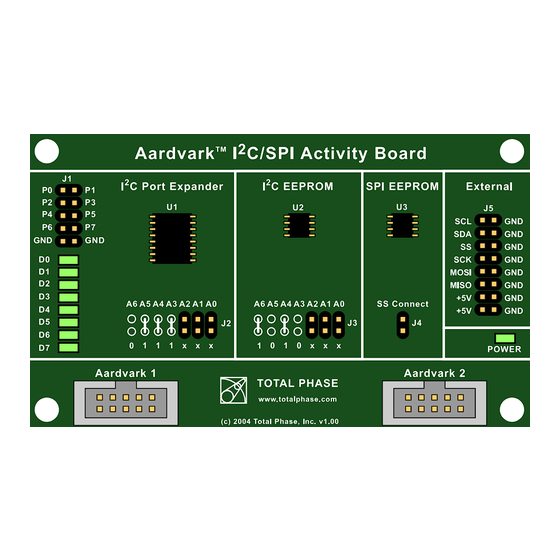
Figure 1: Aardvark I C/SPI Activity Board Targets Please note that these links may become outdated and Total Phase can- not guarantee that they will function. For the latest information about these targets, please visit our website: http://www.totalphase.com/... -
Page 4: Connectors
Total Phase Aardvark I C/SPI Activity Board 2. Connectors There are multiple connectors on the Aardvark I C/SPI Activity Board. Figure 2: Aardvark I C/SPI Activity Board Connectors Port Expander (J1) The pins of J1 are connected directly to the port expander IC. Signals can be connected to an external source through these pins. -
Page 5: External Monitor Connector (J5)
Total Phase Aardvark I C/SPI Activity Board External Monitor Connector (J5) An external bus monitor or logic analyzer can be connected to these pins. Each pin of the J5 connector is labeled with the signal name. C Pins Serial Clock line – the signal used to synchronize communication be- tween the master and the slave. - Page 6 Total Phase Aardvark I C/SPI Activity Board 2.1. Configurable I C Address The I C Port Expander and the I C EEPROM have hardware configurable C addresses. You'll notice on the board the following diagram: Figure 3: Default I C Port Expander address.
-
Page 7: References
C/SPI Activity Board 3. References 3.1. Examples Example scripts which communicate with the target ICs are available for download on the Total Phase website: http://www.totalphase.com/ 3.2. Technical Specifications Detailed information about the Technical Specifications of the Aardvark C/SPI Host Adapter and the Aardvark I... -
Page 8: Contact Information
Internet websites. Only a link to the Total Phase download area can be provided on such public websites. Total Phase shall in no event be liable to any party for direct, indirect, special, general, incidental, or consequential damages arising from the...
Need help?
Do you have a question about the Aardvark I2C/SPI and is the answer not in the manual?
Questions and answers