Table of Contents
Advertisement
Quick Links
GILERA WOULD LIKE TO THANK YOU
for choosing one of its products. We have prepared this manual to help you to get the very best from your vehicle. Please read it carefully before riding
the vehicle for the first time. It contains information, tips and precautions for using your vehicle. It also describes features, details and devices to assure
you that you have made the right choice. We believe that if you follow our suggestions, you will soon get to know your new scooter and it will serve you
well for a long time to come. This booklet forms an integral part of the vehicle; should the vehicle be sold, it must be transferred to the new owner.
Nexus 250 i.e.
Ed. 04_10/2012
Advertisement
Table of Contents

Related Manuals for Gilera Nexus 250 i.e.


Summary of Contents for Gilera Nexus 250 i.e.
- Page 1 GILERA WOULD LIKE TO THANK YOU for choosing one of its products. We have prepared this manual to help you to get the very best from your vehicle. Please read it carefully before riding the vehicle for the first time. It contains information, tips and precautions for using your vehicle. It also describes features, details and devices to assure you that you have made the right choice.
- Page 2 The instructions given in this manual are intended to provide a clear, simple guide to using your vehicle; this booklet also details routine maintenance procedures and regular checks that should be carried out on the vehicle at an authorised Dealer or Service Centre. The booklet also contains instructions for simple repairs.
- Page 3 Personal safety Failure to completely observe these instructions will result in serious risk of personal injury. Safeguarding the environment Sections marked with this symbol indicate the correct use of the vehicle to prevent dam- aging the environment. Vehicle intactness The incomplete or non-observance of these regulations leads to the risk of serious damage to the vehicle and sometimes even the invalidity of the guarantee.
-
Page 5: Table Of Contents
INDEX VEHICLE..................Runningin.................. 36 Dashboard................Startinguptheengine..............37 Instruments................11 Precautions................39 Indicatorunir................12 Difficultstartup................39 Clock..................13 Stoppingtheengine..............40 Digitallcddisplay................ 14 Stand..................40 Maintenanceicons..............15 Automatictransmission.............. 41 Settingthetotalandtripodometers........... 15 Safedriving................42 Settingthedatefunction............16 MAINTENANCE................45 *MODE*button............... 17 Engineoillevel................46 Keyswitch.................. 18 Engineoillevelcheck............... - Page 6 Brakelight.................. 72 Rear-viewmirrors............... 73 Frontandreardiscbrake.............. 74 Puncture..................75 delveicolo.................. 76 Cleaningthevehicle..............76 TECHNICALDATA............... 81 Toolkit..................85 SPAREPARTSANDACCESSORIES........... 87 Warnings................... 88 SCHEDULEDMAINTENANCE............. 91 Scheduledservicingtable............92...
-
Page 7: Vehicle
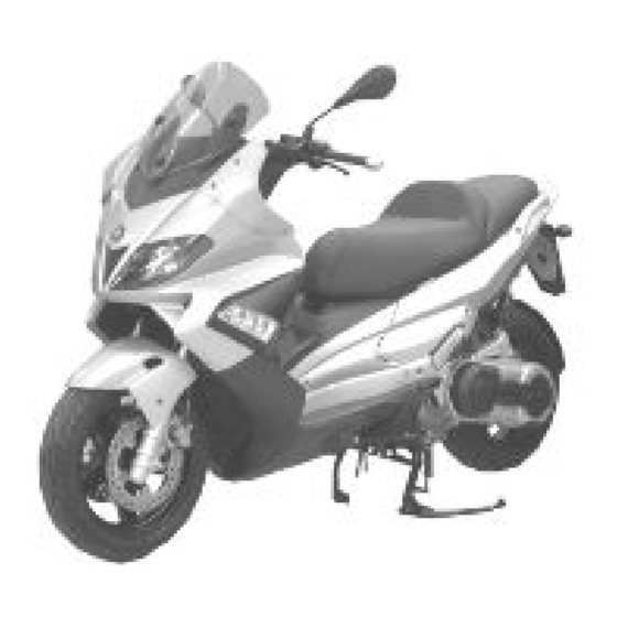
Nexus 250 i.e. Chap. 01 Vehicle... - Page 8 01_01...
-
Page 9: Dashboard
01_02 Dashboard (01_02) A = Ignition key-switch B = Starter button C = Throttle control D = Front brake lever E = Digital instrument panel F = Turn signal switch G = Light switch H = Combined braking system control (front and rear) I = Horn button L = Emergency cut-off switch M = Free position... - Page 10 Q = Remote «Mode» switch R = Passing 01_03...
-
Page 11: Instruments
01_04 Instruments (01_04) A = Twin scale speedometer (km/h and mph) B = Rpm indicator C = Engine control warning light and injection system failure warning light * D = Low fuel warning light M = Low oil pressure warning light F = Turn indicator warning light G = Antitheft device LED H = LCD Display... -
Page 12: Indicatorunir
Indicatorunir (01_05) A = Warning light preinstallation B = Headlight warning light C = High-beam warning light D = Warning light preinstallation 01_05... -
Page 13: Clock
Clock (01_06) Pushing the «CLOCK» button for less than 1 second displays the following sequence: • TIME • DATE • TOTAL/PARTIAL To set the clock push and hold the «CLOCK» button longer than 3 seconds. The numbers showing the hours will begin flashing. Set the hours with the «ODO/SET»... -
Page 14: Digitallcddisplay
Digitallcddisplay (01_07) A = «SERVICE» maintenance icon B = «BELT» maintenance icon C = Battery Icon D = Miles/gallons icon E = Fuel gauge F = 3-digit display G = Miles per hour icon H = Total odometer indicator I = Partial odometer indicator L = Km/h - Km/l indicator M = 5-digit display N = Fuel consumption and autonomy gauge... -
Page 15: Maintenanceicons
Maintenanceicons (01_08) The icons signal the user that scheduled maintenance operations should be carried out. The flashing icon «A» SERVICE signals the need to carry out the scheduled mainte- nance service. The flashing icon «B» BELT signals the driving belt needs to be checked or replaced. In any case, vehicle maintenance must be carried out at the service intervals recom- mended in the Scheduled Maintenance. -
Page 16: Settingthedatefunction
01_09 Settingthedatefunction (01_09) Set «DATE» with the «CLOCK» button. Hold down the «CLOCK» button longer than 3 seconds and the year numbers start flashing. Set the year with the «ODO/SET» button. Push the «CLOCK» button again and the month numbers@ start flashing. Set the month with the «ODO/SET»... -
Page 17: Mode*Button
*MODE*button (01_10) Pushing the "MODE" button for less than a second displays the following function sequence: 1. MEAN SPEED - the word «MEAN» and Km/h or mph is displayed. The value is reset by resetting the trip odometer. 2. MAXIMUM SPEED - the word «MAX» and Km/h or mph are displayed. The value is reset by resetting the trip odometer. -
Page 18: Keyswitch
01_11 Keyswitch (01_11) 1. LOCK = Ignition disabled, extractable key, mechanical antitheft device ena- bled. 2. OFF = Ignition disabled, extractable key, mechanical antitheft device disa- bled. 3. ON = Ready to start, non-extractable key, mechanical antitheft device disa- bled. 4. -
Page 19: Switchdirectionindicators
CAUTION DO NOT TURN THE KEY TO «LOCK» OR «KEY OFF» WHILE RIDING. Switchdirectionindicators (01_12) Lever towards "S" = Left turn indicator is switched on; Lever towards "D" = Right turn indicator is switched on; The lever returns automatically to position "0" and the turn indicator "B" remains on; to switch off, push the lever again. -
Page 20: Lightswitch
Lightswitch (01_14, 01_15) Light switch «A» 0 = Low-beam light 1 = High-beam light E= Passing (flash) 01_14 01_15 Start-upbutton (01_16) Start-up button «C» 01_16... -
Page 21: Enginestopbutton
- The emergency cut-off switch shifts from «OFF» to «ON». If the warning light remains fixedly on after the check period or lights up under normal use conditions, take your vehicle to an Authorised Piaggio- Gilera Service Centre to solve the problem. -
Page 22: Keys
Keys (01_19, 01_20, 01_21) Two types of key are supplied with the scooter. The red-handgrip key «A» is the «MASTER» key. Only a single copy of this key is supplied, which is necessary to program the codes for all your other keys and for your dealer to perform some main- tenance operations. -
Page 23: Immobilizerdeviceenabledindicatorled
(red-coloured). If it is still not possible to start the engine it is absolutely necessary to turn to an Authorised Piaggio-Gilera Service Centre that has the equipment necessary for diagnosis and repair of the system. The immo- bilizer is also activated when the engine cut-off switch stops the engine or the side stand is lowered. -
Page 24: Programmingtheimmobilizersystem
VIOLENT SHOCKS MAY AFFECT THE ELECTRONIC COMPONENTS OF THE KEY. IF OWNERSHIP OF THE VEHICLE IS TRANSFERRED TO ANOTHER PERSON, THE KEY WITH THE RED GRIP (AS WELL AS THE OTHER KEYS) AND THE "CODE CARD" MUST BE ALSO TRANSFERRED TO THE NEW OWNER. Programmingtheimmobilizersystem The procedure for programming the «PIAGGIO IMMOBILIZER»... -
Page 25: Accessingthefueltank
WARNING SHOULD THE ENGINE START WITH THE RED KEY (WITH TRANSPONDER OFF), OR IN THE EVENT OF WRONG OPERATION DURING PROGRAMMING, REPEAT THE PROCEDURE FROM THE BEGINNING. Accessingthefueltank (01_23, 01_24) To remove the fuel tank cover «A» lift tab «B» and insert the key in lock «C». 01_23 01_24... -
Page 26: Powersupplysocket
Powersupplysocket (01_25) There is a plug socket "D" inside the helmet compartment. The plug socket may be used for external consumers (mobile phone, inspection light, etc.). CAUTION 01_25 PROLONGED USE OF THE PLUG SOCKET MAY RESULT IN PARTIAL DIS- CHARGE OF THE BATTERY Electric characteristic Plug socket 12 V - 180 W MAX... -
Page 27: Identification
CAUTION OBJECTS INAPPROPRIATELY PLACED INSIDE THE HELMET COMPARTMENT MAY DEFORM THE SADDLE AND PREVENT THE COURTESY LIGHT FROM TURNING OFF, WHICH MAY RESULT IN BATTERY DISCHARGE. N.B. PAY SPECIAL ATTENTION WHEN PLACING OBJECTS ON THE SADDLE AS THE 01_27 AUTOMATIC OPENING OF THE SADDLE CAN CAUSE THEM TO FALL. Identification (01_28, 01_29) The identification registration numbers consist of a prefix stamped on the chassis and engine "B", followed by a number. -
Page 28: Adjustingthewindscreen
01_29 Adjustingthewindscreen (01_30, 01_31) The windshield can be adjusted to 3 positions «B», «C» and «D» according to the rider's needs. Unscrew the 3 screws «A», remove the windshield upper part and set it in the desired position. Tighten the 3 fixing screws again. WARNING CARRY OUT THIS OPERATION WITH EXTREME CARE SO AS NOT TO 01_30... - Page 29 01_31...
-
Page 31: Use
Nexus 250 i.e. Chap. 02... -
Page 32: Checks
Checks Before using the scooter for the first time check: 1. That the fuel tank is full. 2. Front brake and combined system fluid level. 3. That the tyres are properly inflated. 4. The correct functioning of the tail lights, the headlight, the turn indicators and the stop light. - Page 33 DO NOT ALLOW PETROL TO COME INTO CONTACT WITH HOT ENGINE OR ANY PLASTIC PARTS. CAUTION PETROL DAMAGES THE PLASTIC PARTS OF THE BODYWORK. WARNING 02_02 DO NOT RIDE WITH THE FUEL TANK ALMOST EMPTY, LACK OF FUEL CAN DAMAGE THE CATALYTIC CONVERTER. CAUTION USING NON-RECOMMENDED PETROL REDUCES THE EFFICIENCY OF THE EXHAUST AND FUEL SUPPLY SYSTEMS.
-
Page 34: Tyrepressure
WARNING IT IS HIGHLY INADVISABLE TO REFUEL USING METHODS OTHER THAN NOR- MAL FUEL PUMPS. IF PETROL IS NOT COMPLETELY CLEAN, IT CAN DAMAGE THE FUEL SUPPLY SYSTEM FILTERS. CAUTION USING OILS OTHER THAN THOSE RECOMMENDED CAN SHORTEN THE LIFE OF THE ENGINE. -
Page 35: Shockabsorbersadjustment
CAUTION TYRE PRESSURE SHOULD BE CHECKED WHEN TYRES ARE COLD.INCOR- RECT TYRE PRESSURE CAUSES ABNORMAL TYRE WEAR AND MAKES RID- ING DANGEROUS. TYRES MUST BE REPLACED WHEN THE TREAD REACHES THE WEAR LIMITS SET FORTH BY LAW. Characteristic Front tyre pressure 2.1 bar Rear tyre pressure 2.2 bar with driver only... -
Page 36: Runningin
CAUTION RIDING THE VEHICLE WITH THE SPRING PRELOADING NOT CORRECTLY SET FOR THE RIDER AND POSSIBLE PASSENGER, COULD REDUCE THE COM- FORT OF THE RIDE AND THE PRECISION OF THE STEERING. WARNING WE RECOMMEND WEARING GLOVES WHILE CARRYING OUT THIS OPERA- TION IN ORDER TO AVOID INJURIES. -
Page 37: Startinguptheengine
Startinguptheengine (02_06, 02_07, 02_08) The vehicle is fitted with an ignition disabling system controlled by the side stand and the engine cut-off switch. The engine cannot start if the side stand is down or if the emergency cut-off switch is set to «OFF». If the engine is on, it turns off when the side stand is lowered or the emergency cut-off switch is turned to «OFF». - Page 38 NEITHER PUSH THE START BUTTON WHEN THE TANK IS EMPTY NOR TURN THE KEY SWITCH TO «ON» TO AVOID DAMAGING THE INJECTION SYSTEM. CAUTION DO NOT START-UP THE ENGINE IN CLOSED AREAS BECAUSE EXHAUST GASES ARE TOXIC. CAUTION DUE TO THE HIGH TEMPERATURES THE CATALYTIC CONVERTER CAN REACH, ALWAYS TAKE CARE, WHEN PARKING THE VEHICLE, THAT THE EX- HAUST DOES NOT COME INTO CONTACT WITH FLAMMABLE MATERIALS, TO AVOID SERIOUS BURNS.
-
Page 39: Precautions
It is however necessary, once the engine is started, to take your vehicle to an Authorised Piaggio- Gilera Service Centre to determine the causes and to restore proper functioning of your vehicle. -
Page 40: Stoppingtheengine
Stoppingtheengine (02_09) Fully untwist the throttle grip, then rotate the key in the switch «A » to «KEY OFF» (extractable key). 02_09 Stand (02_10) CENTRE STAND Push with your foot on the centre stand's fork "F" while lifting the vehicle backward, holding onto the handlebar. -
Page 41: Automatictransmission
Stand (02_10, 02_11) SIDE Push with your foot on the stand's prong «L» until it releases into position, while low- ering the vehicle onto the stand. WARNING 02_11 THE SIDE STAND CAUSES THE ENGINE TO TURN ITSELF OFF WHENEVER IT IS LOWERED. -
Page 42: Safedriving
Safedriving (02_13) Some simple tips are provided below that will enable you to use your vehicle on a daily basis in greater safety and peace of mind. Your skill and your mechanical knowledge are the basis of safe riding. We recommend trying out the vehicle in traffic-free zones in order to acquire a good knowledge of the vehicle itself. - Page 43 NEVER RIDE FASTER THAN 100 km/h WITH A SCOOTER WITH ADDED AC- CESSORIES . WITHOUT THESE ACCESSORIES THE VEHICLE MAY BE DRIVEN AT A HIGHER SPEED WITHIN THE LEGAL LIMITS. IF THERE ARE NOT PAIGE ACCESSORIES FITTED, OR AN ABNORMAL LOAD, OR IF THE VEHICLE IS NOT IN A GENERALLY GOOD CONDITION, OR WHENEVER WEATHER CONDITIONS DEMAND IT, SPEED SHOULD BE FURTHER REDUCED.
-
Page 45: Maintenance
Nexus 250 i.e. Chap. 03 Maintenance... -
Page 46: Engineoillevel
Engineoillevel In 4-stroke engines, engine oil is used to lubricate the distribution elements, the bush- es and the thermal group. An insufficient quantity of oil can cause serious damage to the engine.In all four-stroke engines, a loss of efficiency in oil performance and certain consumption should be considered normal. -
Page 47: Engineoiltop-Up
03_02 Engineoiltop-up Any topping up with oil must be carried out after the oil level check by adding oil, but never exceeding the MAX level. The topping up of the level between MIN and MAX requires approx. 200 cc of oil. Every 5000 km, however, the engine oil level should be checked and topped up, if necessary, at an Authorised Piaggio Service Centre. -
Page 48: Warninglight(Insufficientoilpressure) (03_03
Warninglight(insufficientoilpressure) (03_03) The vehicle is fitted with a warning light «E» that is turned on when the key is turned to «ON». This warning must go off once the engine starts. If the light comes on during braking, at idling speed or while turning a corner, it is necessary to check the oil level and top up if required. -
Page 49: Huboillevel
CAUTION USED OILS CONTAIN SUBSTANCES HARMFUL TO THE ENVIRONMENT. FOR OIL CHANGE, CONTACT AN AUTHORISED SERVICE CENTRE WHICH IS EQUIP- PED TO DISPOSE OF USED OILS IN AN ENVIRONMENTALLY FRIENDLY AND LEGAL WAY. CAUTION USING OILS OTHER THAN THOSE RECOMMENDED CAN SHORTEN THE LIFE OF THE ENGINE. - Page 50 N.B. THE NOTCHES ON THE HUB OIL LEVEL DIPSTICK, EXCEPT THE ONE INDI- CATING THE MAX LEVEL, REFER TO OTHER MODELS BY THE MANUFACTUR- ER AND HAVE NO SPECIFIC FUNCTION FOR THIS MODEL. CAUTION RIDING THE VEHICLE WITH INSUFFICIENT HUB LUBRICATION OR WITH CON- 03_07 TAMINATED OR IMPROPER LUBRICANTS ACCELERATES THE WEAR AND TEAR OF THE MOVING PARTS AND CAN CAUSE SERIOUS DAMAGE.
-
Page 51: Tyres
CAUTION FOR OIL REPLACEMENT, CONTACT ANY AUTHORISED SERVICE CENTRE AS THEY ARE EQUIPPED TO DISPOSE OF USED OILS IN AN ENVIRONMENTALLY FRIENDLY AND LEGAL WAY. Characteristic Rear hub oil 250 cc Tyres (03_09) Check pressure and tyre wear periodically (about every 500 km). The tyres are equipped with wear indicators. - Page 52 CAUTION THE USE OF TYRES OTHER THAN THOSE INDICATED MAY CAUSE INSTABIL- ITY. IT IS HIGHLY ADVISABLE TO USE ORIGINAL PIAGGIO TYRES. Characteristic Front tyres Tubeless 120/70 - 14" 55P Rear tyre Tubeless, 140/60 - 14'' 64P Front tyre pressure 2.1 bar Rear tyre pressure 2.2 bar with driver only...
-
Page 53: Sparkplugdismantlement
Sparkplugdismantlement (03_10, 03_11) Proceed as follows: 1. Remove the right side cover unscrewing the 3 «A» screws; 2. Disconnect the spark plug HV wire hood «B» ; 3. Unscrew the spark plug using the wrench supplied. ; 4. When refitting, place the spark plug in the hole at the due inclination and tighten it by hand until it is finger tight;... -
Page 54: Removingtheairfilter
Locking torques (N*m) Spark plug 12 ÷ 14 Removingtheairfilter (03_12, 03_13) Proceed as follows: 1. Unscrew the 9 fixing screws «A»; 2. Remove the air filter«B» CAUTION 03_12 IF THE VEHICLE IS USED ON DUSTY ROADS IT IS NECESSARY TO CARRY OUT MAINTENANCE CHECKS OF THE AIR FILTER MORE OFTEN TO AVOID DAM- AGING THE ENGINE. -
Page 55: Airfiltercleaning
Airfiltercleaning (03_14) 1. Wash the sponge with water and mild soap. 2. Dry it with a clean cloth and short blasts of compressed air. 3. Impregnate the sponge with a mixture of 50% petrol and 50% specified oil. 4. Gently squeeze the filtering element, let it drip dry and then refit it. CAUTION 03_14 IF THE VEHICLE IS USED ON DUSTY ROADS IT IS NECESSARY TO CARRY OUT... -
Page 56: Coolingfluidlevel
It is therefore essential to have the cooling system checked at an Authorised Piaggio-Gilera Service Cen- tre. The coolant should be changed every 2 years. Take your vehicle to an Authorised 03_16 Piaggio-Gilera Service Centre for this operation. -
Page 57: Checkingthebrakeoillevel
2. Check fluid level through the related warning light «A». A certain lowering of the level is caused by wear on the pads. Should the level appear to be below the minimum mark, please contact your nearest PIAGGIO-GILERA Deal- 03_18... -
Page 58: Brakingsystemfluidtopup
Under normal climatic conditions, the brake fluid must be replaced every 20,000 km or every two years, whichever comes first. This operation must be carried out by trained technicians, please contact your nearest Piaggio-Gilera Dealer or Author- ised Service Centre. -
Page 59: Battery
Synthetic fluid SAE J 1703 -FMVSS 116 - DOT 3/4 - ISO 4925 - CUNA NC 956 DOT Battery (03_21, 03_22) To access the battery, proceed as follows: 1. Place the scooter on its centre stand; 2. Open the saddle following above instructions, see «Saddle» section; 3. -
Page 60: Checkingtheelectrolytelevel
CAUTION DO NOT REVERSE THE POLARITY: RISK OF SHORT CIRCUIT AND DAMAGE TO THE ELECTRICAL SYSTEM. Checkingtheelectrolytelevel The electrolyte level, which should be checked regularly, must always be at the max- imum level. To top it up to this level, use only distilled water. Should it become necessary to top up the battery with water too frequently, check the scooter's electrical system because the battery is being overloaded, causing it to lose power quickly. -
Page 61: Long Periods Of Inactivity
THE BATTERY MUST BE RECHARGED WITH A CURRENT LOAD EQUAL TO 1/10 OF THE BATTERY RATED CAPACITY AND FOR A PERIOD NOT LONGER THAN 10 HOURS. CONTACT AN AUTHORISED PIAGGIO-GILERA SERVICE CENTRE TO CARRY OUT THIS OPERATION SAFELY. WHEN INSTALLING THE BATTERY AGAIN, ENSURE THAT THE TERMINALS ARE CORRECTLY CONNECTED TO THE TERMINALS. -
Page 62: Fuses
Fuses (03_23, 03_24, 03_25, 03_26) The electric system is fitted with 2 fuse boxes: 1. Fuse box «A» 6 fuses located in the helmet compartment near the battery. 2. Fuse box «B» 6 fuses located in the helmet compartment near the plug socket. - Page 63 Fuse 10A Protected circuits:H.V. coil - Fuel injector - Fuel pump - Lambda sensor Location: Helmet compartment front side fuse box. Fuse 15A Protected circuits: Lines protected by fuses No 8,9,10,11. Location: helmet compartment, front side fuse box. Fuse 15A Protected circuits: Radiator...
- Page 64 CAUTION BEFORE REPLACING A BLOWN FUSE, FIND AND SOLVE THE FAILURE THAT CAUSED IT TO BLOW. NEVER TRY TO REPLACE THE FUSE WITH ANY OTHER MATERIAL (E.G., A PIECE OF ELECTRIC WIRE). 03_25 03_26 FUSE BOX_B Fuse 7.5A Protected circuits: Digital instrument panel, Turn indicator bulbs, Radiator electric fan remote...
- Page 65 Location: Helmet compartment, rear side fuse box. Fuse 7.5A Protected circuits: Digital instrument panel, Antitheft device preinstallation Location: Helmet compartment, rear side fuse box. Fuse 7.5A Protected circuits: Analogue rpm indicator and digital Instrument panel Location: Helmet compartment, rear side fuse box. Fuse 7.5A Protected circuits: Stop bulb, Engine start-up circuit, Horn...
- Page 66 BULBS High/low beam light bulb Type: Halogen (H7) Power: 12V - 55W Quantity: 2 Front headlights bulb Type: ALL GLASS Power: 12V - 5W Quantity: 2 Rear turn indicator bulbs Type: Spherical Colour: Amber Power: 12V-10W Quantity: 2 Front turn indicator bulbs Type: All glass Colour: Amber Power: 12V - 5W...
-
Page 67: Frontlightgroup
Frontlightgroup (03_27, 03_28, 03_29, 03_30, 03_31) To remove the rear light assembly, proceed as follows: 1. Pull the Gilera emblem off with a plain slot screwdriver. 2. Remove the front shield connection unscrewing the two screws «A». 3. Remove the two screws «B». - Page 68 03_29 03_30...
-
Page 69: Headlightadjustment
03_31 Headlightadjustment (03_32, 03_33) Proceed as follows: 1. Place the vehicle in riding condition and with the tyres correctly inflated on a flat piece of ground at a distance of 10 m from a white screen situated in a shaded area, making sure that the scooter is perpendicular to the screen;... -
Page 70: Frontdirectionindicators
03_33 Frontdirectionindicators (03_34, 03_35) To replace the burnt out bulb remove the 3 screws shown in the figure and then take the rubber holder off its socket; WARNING HIGH- AND LOW-BEAM BULBS ARE HALOGEN TYPE: DO NOT TOUCH THEM WITH YOUR FINGERS TO AVOID DAMAGING THEIR FUNCTION. 03_34 03_35... -
Page 71: Rearturnindicators
Rearturnindicators (03_36) Operate the screw indicated in the figure and remove glass C. 03_36 Numberplatelight (03_37) Loosen the two screws «D», remove the plastic cover behind the mudguard. Remove screw «E» from behind the mudguard. Remove the bulb socket. 03_37... -
Page 72: Helmetcompartmentlightingbulb
Helmetcompartmentlightingbulb (03_38) Open the helmet compartment, take out the pressure mounted glass cover «F» and replace the bulb. 03_38 Brakelight (03_39, 03_40, 03_41) To remove the stop and tail light, proceed as follows: 1. Open the saddle and remove the rear cover unscrewing the two screws «A» 2. -
Page 73: Rear-Viewmirrors
03_40 03_41 Rear-viewmirrors (03_42, 03_43) To adjust mirrors, loosen the lock nut «A», place the mirror stem adequately and tighten the lock nut. The rear-view mirror is assembled on a stem with a ball 'joint'. The mirror can be adjusted to the desired position manually. 03_42... -
Page 74: Frontandreardiscbrake
ER, IN THE EVENT OF NOISES COMING FROM THE FRONT AND/OR REAR BRAKE SYSTEM DURING OPERATION, IT IS ADVISABLE TO HAVE THE BRAKE SYSTEM CHECKED BY A PIAGGIO-GILERA DEALER OR AUTHORISED SERV- ICE CENTRE. AFTER REPLACING THE BRAKE PADS DO NOT USE THE SCOOT-... -
Page 75: Puncture
«inflate and repair» spray. In order to repair a tyre completely, take your vehicle to a Piaggio-Gilera Dealer or Authorised Service Centre. The replacement of a type involves removing the wheel in question. Take your vehicle to a Piaggio-Gilera Dealer or Authorised Service Centre for these operations. -
Page 76: Delveicolo
WARNING THE WHEELS FITTED WITH TYRES SHOULD ALWAYS BE BALANCED. RIDING THE VEHICLE WITH VERY LOW TYRE PRESSURE OR WITH INCORRECTLY BALANCED TYRES CAN LEAD TO DANGEROUS STEERING VIBRATIONS. delveicolo (03_46) The following operations are recommended: 1. Clean the scooter thoroughly and then cover it with a canvas; 2. - Page 77 for bodywork soaked in water and "shampoo" (2-4% of shampoo in water). Then rinse abundantly with water, and dry with a shammy cloth. For the outside of the engine, use petroleum, a brush and clean cloths. Petroleum is harmful for the paint. Remem- ber that any polishing with silicon wax must always be preceded by washing CAUTION DETERGENTS CAN POLLUTE WATER.
- Page 78 Set the switch back to «ON» Side stand down Lift stand Fuse blown Replace the blown fuse and have the scooter checked by an Authorised Piaggio-Gilera Service Centre. STARTING DIFFICULTIES (SEE SECTION "DIFFICULT STARTING") Lack of fuel in tank. Refuelling...
- Page 79 COULD CAUSE DAMAGE TO THE FUEL PUMP AND/OR THE CATALYTIC CONVERTER. IGNITION PROBLEM Faulty spark plug Contact an Authorised Piaggio- Gilera Service Centre Faulty ignition / injection control Contact an Authorised Piaggio- unit. Due to the presence of high Gilera Service Centre voltage, this element should only be checked by an expert.
- Page 80 INSUFFICIENT BRAKING Greasy disc. Worn pads. Faulty Contact an Authorised Piaggio- brake system. Presence of air in Gilera Service Centre the front and rear brake circuit. Presence of air in the front and rear Contact an Authorised Piaggio- brake circuit.
-
Page 81: Technicaldata
Nexus 250 i.e. Chap. 04 Technicaldata... - Page 82 04_01...
- Page 83 TECHNICAL DATA Length 2100 mm Width 780 mm Wheelbase 1530 mm Height 1330 mm Saddle height 800 mm Frame Welded tubular steel structure, with asymmetrical frame structure, front beams and union elements in stamped sheets. Front suspension Hydraulic telescopic fork with Ø 35- mm stem Rear suspension Single arm with two double-acting...
- Page 84 Vacuum weight 174 +/- 5 kg Maximum load 180 kg. Fuel tank capacity 15 l (approx.) Fuel reserve 2 l (approx.) Rear hub oil 250 cc Engine oil Capacity: 1.3 l (dry); 1.2 l (when changing oil and filter) Cooling circuit Capacity: ~ 2.0 l Air filter Sponge, soaked in a mixture (50%...
-
Page 85: Toolkit
Valve clearance intake: 0.10 mm discharge: 0.15 mm Engine oil Capacity: 1.3 l (dry); 1.2 l (when changing oil and filter) Maximum power (CE) 16.5 kW at 8000 rpm Maximum torque (CE) 21 Nm at 6250 rpm Fuel system Electronic injection with electric fuel pump. - Page 86 • A pair of pliers to extract fuses. • Wrench for adjusting shock absorbers. The tools are stored in the helmet compartment.
-
Page 87: Sparepartsandaccessories
Nexus 250 i.e. Chap. 05 Sparepartsanda ccessories... -
Page 88: Warnings
Warnings (05_01) WARNING TO PREVENT ACCIDENTS AND TO GUARANTEE PROPER STABILITY, PER- FORMANCE AND SAFETY, RIDE THE VEHICLE VERY CAREFULLY WHEN IT IS FITTED WITH ACCESSORIES OR WITH UNUSUAL LOADS. WARNING 05_01 IT IS ALSO RECOMMENDED THAT ORIGINAL PIAGGIO SPARE PARTS BE USED, AS THESE ARE THE ONLY ONES OFFERING YOU THE SAME QUALITY GUARANTEE AS THOSE INITIALLY FITTED ON THE SCOOTER. - Page 89 WARNING NEVER RIDE THE SCOOTER EQUIPPED WITH ACCESSORIES (TOP BOX AND/ OR WINDSHIELD) AT A SPEED HIGHER THAN 100 km/h. THE SCOOTER CAN BE RIDDEN AT A HIGHER SPEED WITHOUT THE ACCES- SORIES MENTIONED BEFORE WITHIN THE LIMITS ESTABLISHED BY LAW. IF THERE ARE ANY NON-PIAGGIO ACCESSORIES INSTALLED, OR AN AB- NORMAL LOAD, OR IF THE SCOOTER IS NOT IN A GENERALLY GOOD CON- DITION, OR WHENEVER WEATHER CONDITIONS DEMAND IT, SPEED SHOULD...
- Page 91 Nexus 250 i.e. Chap. 06 Scheduledmaint enance...
-
Page 92: Scheduledmaintenance
Scheduledservicingtable (06_01) Adequate maintenance is fundamental to ensuring long-lasting, optimum operation and performance of your vehicle. To this end, a series of checks and maintenance operations (at the owner's expense) have been suggested, which are included in the summary table on the following page. Any minor faults should be reported without delay to an Authorised Service Centre or Dealer without waiting until the next scheduled service to solve it. - Page 93 km x 1,000 Coolant * Engine oil Hub oil Brake pads Sliding shoes / CVT rollers Tyre pressure and wear Vehicle road test Suspension Steering I: CHECK AND CLEAN, ADJUST, LUBRICATE OR REPLACE IF NECESSARY. C: CLEAN, R: REPLACE, A: ADJUST, L: LUBRICATE * Replace every 2 years RECOMMENDED PRODUCTS TABLE Product...
- Page 94 Product Description Specifications eni i-Ride PG 5W-40 Synthetic based lubricant for high-performance JASO MA, MA2 - API SL - ACEA A3 four-stroke engines. AGIP BRAKE 4 Brake fluid. Synthetic fluid SAE J 1703 -FMVSS 116 - DOT 3/4 - ISO 4925 - CUNA NC 956 DOT 4 AGIP PERMANENT SPEZIAL Ethylene glycol-based antifreeze fluid with ASTM D 3306 - ASTM D 4656 - ASTM D 4985...
- Page 95 TABLE OF CONTENTS Battery: 59 Puncture: 75 Checks: 32 Refuelling: 32 Clock: 13 Stand: 40, 41 Fuses: 62 Toolkit: 85 Identification: 27 Tyres: 51 Keys: 22 Vehicle: 7 Maintenance: 45...
- Page 96 The descriptions and images in this publication are given for illustrative purposes only and are not binding. While the basic characteristics as described and illustrated in this booklet remain unchanged, Piaggio & C. S.p.A. reserves the right, at any time and without being required to update this publication beforehand, to make any changes to components, parts or accessories, which it considers necessary to improve the product or which are required for manufacturing or construction reasons.
Need help?
Do you have a question about the Nexus 250 i.e. and is the answer not in the manual?
Questions and answers