
Related Manuals for YOKOGAWA CW240


Summary of Contents for YOKOGAWA CW240
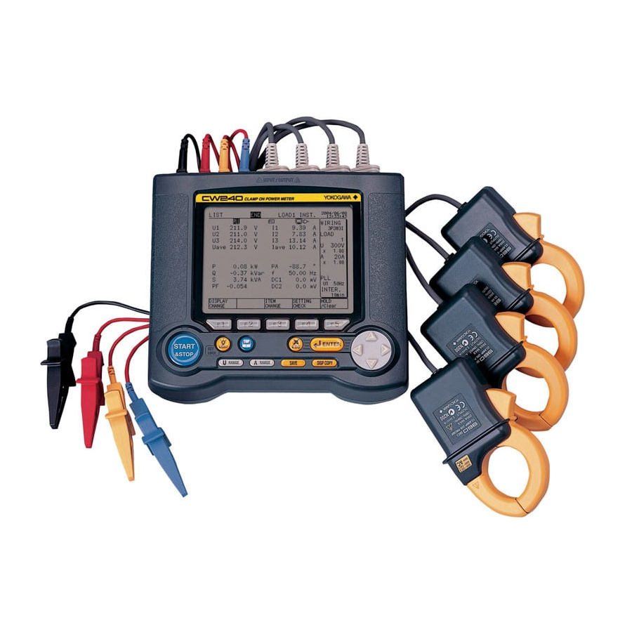
- Page 1 User's CW240 Clamp-on Power Meter Manual IM CW240E IM CW240E 1st Edition: June 2004 (KP)
-
Page 2: Table Of Contents
Index Introduction ..................1 Checking the Contents of the Package ........2 Precautions for Safe Use of the Instrument ........ 6 Utilisation en Toute Securite ............9 Chapter 1 Product Overview ........1-1 Product Overview .............. 1-2 System Configuration Diagram ........1-4 Chapter 2 Part Names and How to Use Parts .. - Page 3 Index Chapter 4 Wiring ............4-1 Precautions for Wiring to the Measurement Circuit ..4-2 Installing the CW240 ............4-3 Setting up Wiring ............... 4-5 Setting up the Number of Loads ........4-6 Carrying out Wiring ............4-7 Wiring the Measurement Circuit Using External VT/CT ............
- Page 4 Index Chapter 7 Measurements .......... 7-1 Measurements ..............7-2 Measure Screens ............... 7-3 Measuring Electric Energy ..........7-13 Measuring Demand ............7-17 Displaying Zoom (Expanded View) ........ 7-21 Measuring Harmonics ............. 7-24 Displaying Waveform ............7-34 Measuring Voltage Quality (Voltage Dip, Voltage Swell, or Instantaneous Interruption) ....
- Page 5 Chapter 12 Using External Control Input/Output ... 12-1 12.1 External Control Input/Output ........12-2 12.2 Connecting External Control Terminals ......12-3 12.3 Using Multiple CW240 Units in Synchronization ..12-4 Chapter 13 Using Analog Input/Output (Optional) ..........13-1 13.1 Analog Output (DA Output) ..........13-2 13.2 Analog Input ..............
- Page 6 Index Appendix 1 Block Diagram ........App.1-1 Appendix 2 File/Print Item Descriptions .... App.2-1 Appendix 3 Polarity (Active Power, Reactive Power, Power Factor, Phase Angle) .... App.3-1 Appendix 4 Polarity (Harmonic Measurement) ....App.4-1 Appendix 5 Reactive Power Method....App.5-1 Appendix 6 Sampling Method ......
-
Page 7: Introduction
Introduction Thank you for purchasing our CW240 Clamp-on Power Meter. This User's Manual describes the functions of the CW240 as well as its operating methods and handling precautions. Read this manual thoroughly before using the CW240, to ensure correct use. -
Page 8: Checking The Contents Of The Package
Instrument Main Unit Check the model name where MODEL is printed on the nameplate located at the back of the CW240 to ensure that the CW240 is exactly as specified in your purchase order. Model and Suffix Codes... -
Page 9: Im Cw240E
Product Name Part No. Q'ty Remarks 1. AC adapter for 788011 1set Yokogawa's AC adapter power supply 2. AA-size alkaline batteries 3. Voltage probes 91007 Color: black, red, yellow, blue 4. User's Manual IM CW240 5. - Page 10 2 A 96036 Voltage probe 91007 1 set Carrying case 93020 AC adapter 788011 1 set Yokogawa's AC adapter NiMH battery pack 94004 AC adapter for 96035 A1020UP 1 For clamp-on Probes Printer 97010 AC adapter (for printer, Europe) 94006...
-
Page 11: Im Cw240E
Checking the Contents of the Package Housing the CW240 Main Unit and Accessories An optional carrying case can accommodate the CW240 main unit with its clamp-on probes and voltage probes connected to the unit. The case can also house such accessories as the memory card, AC adapter, and User's Manual. -
Page 12: Precautions For Safe Use Of The Instrument
If you use the instrument in any way other than as instructed in this manual, the instrument’s protective measures may be impaired. Yokogawa M&C Corporation is by no means liable for any damage resulting from use of the instrument in contradiction to these cautionary notes. - Page 13 Precautions for Safe Use of the Instrument NOTE Indicates information that is essential for handling the instrument or, should be noted in order to familiarize yourself with the instrument’s operating procedures and/or functions. Indicates information that complements the present topic. SEE ALSO Indicates the reference location(s) for further information on the present topic.
- Page 14 •Do not use clamp-on current probes with any non-insulated conductors. ● Handling of Power Cord •Use only the cord supplied from Yokogawa M&C to prevent electric shocks and fire. •Do not place any load on the power cord or allow the power cord to come into accidental contact with any heat source.
-
Page 15: Utilisation En Toute Securite
Utilisation en Toute Securite Les précautions suivantes doivent être prises pendant l'exploitation, la maintenance et les réparations. YOKOGAWA M&C ne pourra en rien être déclaré responsable si ces précautions ne sont pas respectées par l'utilisateur. ● Symboles utilisés sur les appareils et dans les Manuels d'instruction. - Page 16 Utilisation en Toute Securite AVERTISSEMENT ● Retrait du boîtier de l'instrument •Ne pas retirer le boîtier de l'instrument et ne pas essayer non plus de démonter/modifier l'instrument lui-même. •L'instrument renferme des composants parcourus par des tensions élevées. Il est donc extrêmement dangereux d'accéder à ses circuits internes. Pour vérifier et/ou régler les circuits internes, contacter le revendeur auprès duquel a été...
- Page 17 ● Manipulation du cordon d'alimentation •Afin de prévenir tout feu ou choc électrique, n'utilisez que le cordon fourni par Yokogawa M&C. •Ne déposer aucune charge sur le cordon d'alimentation et éviter tout con- tact fortuit entre celui-ci et une source de chaleur. Pour débrancher le cor- don de la prise secteur, tirer sur sa fiche, mais jamais sur le fil proprement dit.
-
Page 18: Chapter 1 Product Overview
Chapter 1 Product Overview Chapter 1 Product Overview 1.1 Product Overview ........1-2 1.2 System Configuration Diagram ....1-4... - Page 19 Chapter 1 Product Overview Product Overview The CW240 is a clamp-on power meter that measures items necessary for various power measurements or power quality analyses to conduct an energy- saving diagnosis or ISO 14001 testing. The measurement items are as shown below and are all measured simultaneously.
- Page 20 • Measured values can be converted into DC voltage and then analog-output to a recorder or other devices. • Analog outputs from a thermometer or illuminometer can be connected to the analog input terminals of the CW240 to measure power data and environmental data together. IM CW240E...
-
Page 21: System Configuration Diagram
System Configuration Diagram IM CW240E... -
Page 22: Chapter 2 Part Names And How To Use Parts
Chapter 2 Part Names and How to Use Parts Chapter 2 Part Names and How to Use Parts 2.1 Front Panel and Connector Block .... 2-2 2.2 Operation Keys ......... 2-3 2.3 Side Faces ..........2-4 2.4 Screen Configuration ....... 2-5 2.5 Overrange/Error Indication during Measurement .......... -
Page 23: Front Panel And Connector Block
Chapter 2 Part Names and How to Use Parts Front Panel and Connector Block Voltage input terminals Current input terminals Connect the voltage Connect clamp-on current probes to these terminals. probes to these terminals. U1 U2 U3 RS-232 connector Analog input terminals (optional) Connect a PC or printer using Used for DC voltage inputs. -
Page 24: Operation Keys
Operation Keys START ENTER &STOP MENU LIGHT SAVE DISP COPY RANGE RANGE Key Name Functional Description Function keys These are setting keys corresponding to the information displayed in the bottom of the screen. START & STOP key Starts/stops integration measurements. LIGHT key Turns the backlight ON/OFF. -
Page 25: Side Faces
Side Faces Lights up while a NiMH battery pack (optional) is charged. PC card slot AC adapter jack Button for extracting Connect the AC adapter a PC card (accessorie) to this jack. Power switch Battery holder : Power OFF This part holds the alkaline battery holder (accessorie) or : Power ON NiMH battery holder (optional). -
Page 26: Screen Configuration
Screen Configuration ● Basic Screen Configuration ENTER START MENU LIGHT &STOP SAVE DISP COPY RANGE RANGE MEASURE screen SETUP screen FILE screen LIST (instantaneous values) GENERAL (1/2, 2/2) FILE NAME CHANGE POWER SAVE (1/2, 2/2) DELETE FILE INTEGRATE COMMUNICATION FORMAT DEMAND ZOOM VOLT. -
Page 27: Overrange/Error Indication During Measurement
CH1 to CH4 satisfies the noted conditions. Indication of "OR" or "----" symbol The CW240 indicates "OR" or "----" symbol instead of a usual four-digit value if the measured value meets the noted conditions. WARNING The CW240 shows an overrange mark in the maximum range only if the input level exceeds the maximum allowable level. - Page 28 2.5 Overrange/Error Indication during Measurement • Instantaneous value, electric energy, demand Measurement Item Conditions and Indications Voltage rms If the peak value of an input signal exceeds 300% (180% for the 1000 V range) of the measurement range, or if the rms value of measured voltage exceeds 130% of the rated range, "OR"...
- Page 29 2.5 Overrange/Error Indication during Measurement • Harmonics Measurement Item Conditions and Indications Voltage rms If the peak value of an input signal exceeds 300% (180% for a 1000 V range) of the measurement range, or if the rms value of measured voltage exceeds 130% of the rated range, "OR"...
- Page 30 2.5 Overrange/Error Indication during Measurement ● Indication Provided if a Measured Value is Too Small • Instantaneous value, electric energy, demand Measurement Item Conditions and Indications Voltage If an input level is below 0.4% of the rated range, the reading becomes "0 V".
- Page 31 2.5 Overrange/Error Indication during Measurement ● Indications on the basis of other input conditions Measurement Item Conditions and Indications Electric energy • When the display setting is any item other than AUTO, if the Reactive energy integrated value exceeds "999999", the reading is reset to "0", letting integration continue.
-
Page 32: Description Of Mark Indication
Appears if the amount of data exceeds the capacity of a PC card or the internal memory. Appears when the CW240 is configured so that data is saved in a PC card. Also, this mark flashes during an access to the PC card. -
Page 33: Chapter 3 Preparation For Safe Measurements
Chapter 3 Preparation for Safe Measurements Chapter 3 Preparation for Safe Measurements 3.1 Precautions for Use ........3-2 3.2 Connecting a Power Supply ..... 3-4 3.3 Connecting Voltage Probes ....3-14 3.4 Connecting Clamp-on Probes ....3-15 3.5 Connection Diagrams of Voltage Probes and Clamp-on Probes ...... -
Page 34: Precautions For Use
Precautions for Use If you are a first-time user, always read the "Precautions for Safe Use of the CW240" on pages 6 through 11. ● Do not place any objects on the Instrument. Do not place another device or a container filled with water on the instrument, otherwise, the instrument may become defective. - Page 35 3.1 Precautions for Use Precautions for Using Clamp-on Probes CAUTION • The clamping CT (current transformer) is precision assembled to ensure high performance. When using a clamp, do not apply any intense mechanical shock, vibration, or force to the clamping CT. •...
-
Page 36: Connecting A Power Supply
• Check that the power source voltage matches the supply voltage rating of the AC adapter, and then connect the power cord to the outlet. • Check that the power switch of the CW240 is turned OFF and then connect the power cord. - Page 37 ● Procedure for Connecting the AC Adapter Follow the steps below to connect the AC adapter. <1> Check that the power switch of the CW240 is turned OFF. (Attach the clamp filter to the output-side cable of the AC adapter.) <2>...
- Page 38 (of the same manufacturer). (Do not use manganese batteries as replacements.) • If the CW240 will not be used for a prolonged period, remove the batteries. ● Backup Hours by Alkaline Batteries The number of backup hours available using alkaline batteries varies with the operating environment and conditions.
- Page 39 A decrease in the battery voltage (remaining capacity) is indicated in the following four steps: → → → NOTE If you continue to operate the CW240 with this mark displayed, the CW240 will be turned OFF automatically. Replace the alkaline batteries with new ones before this mark appears. IM CW240E...
- Page 40 <1> Check that the power switch is OFF and no AC adapter has been connected. <2> Raise the battery holder lock switch at the back of the CW240 to remove the alkaline battery holder. <3> Remove the old batteries from the battery holder and insert six new alkaline batteries.
- Page 41 Then see a doctor quickly for treatment. • When replacing the NiMH battery pack, always turn the CW240 power switch OFF and disconnect the AC adapter power cord from the outlet to avoid possible danger such as a short in the electric circuit or electrical shock.
- Page 42 • Do not immerse the battery pack in water or make it wet. Otherwise, it may heat up or rust as well as leading to a loss of functions. • If the battery pack is not used for a prolonged period, remove it from the CW240 and store it in the following environment.
- Page 43 <4> Insert NiMH battery pack <3> If using alkaline batteries, raise the lock switch at the back of the CW240 to remove them from the battery holder. Then install the NiMH battery pack into the holder. <4> Place the battery holder into the holder inlet of the CW240. Slide the battery holder into the slot, so that the battery holder connector connects properly with the battery connector.
- Page 44 The NiMH battery pack will be recharged regardless of the ON/OFF of the power switch. In this case, power is supplied through the AC adapter. When the LED indicator is flashing, the CW240 is in a waiting-to-be-recharged state. The CW240 falls into this state if: •...
- Page 45 3.2 Connecting a Power Supply ● Backup Hours with a NiMH Battery Pack The number of backup hours available using a NiMH battery pack vary with the operating environment and conditions. Refer to the table below. Operating Conditions Backup Hours Available LCD backlight OFF Approx.
-
Page 46: Connecting Voltage Probes
Connecting Voltage Probes WARNING • For safety, connect voltage probes to the CW240 main unit and then to the circuit under test. • Before attaching a voltage probe to the circuit under test, turn off power to the circuit under test. It is very dangerous to connect or disconnect a voltage probe without turning off the circuit under test. -
Page 47: Connecting Clamp-On Probes
Connecting Clamp-on Probes WARNING • For safety, connect a clamp-on probe to the CW240 main unit and then to the circuit under test. • Before clamping a clamp-on current probe onto the circuit under test, turn off power to the circuit under test. It is very dangerous to clamp or unclamp the clamp-on probe without turning off the circuit under test. - Page 48 3.4 Connecting Clamp-on Probes ● Connecting Clamp-on Probes When connecting a clamp-on probe to the CW240 main unit, connect the plug of the clamp-on probe so that the groove in the plug agrees with the guide in the CW240 main unit (that the H and L polarities are correctly connected).
-
Page 49: Connection Diagrams Of Voltage Probes And Clamp-On Probes
Connection Diagrams of Voltage Probes and Clamp-on Probes Single-phase two-wire/Single load Single-phase two-wire/Two loads (1P2W) (1P2W) Load 1 Load 1 Load 2 Single-phase two-wire/Four loads Single-phase two-wire/Three loads (1P2W) (1P2W) Load 1 Load 2 Load 3 Load 2 Load 3 Load 1 Load 4 3-17... - Page 50 3.5 Connection Diagrams of Voltage Probes and Clamp-on Probes Single-phase three-wire/Two loads Single-phase three-wire/Single load (1P3W) (1P3W) Load 1 Load 2 Load 1 Load 2 Single-phase three-wire three-current (1P3W3I) <Measurement of neutral line current> 3-18 IM CW240E...
- Page 51 3.5 Connection Diagrams of Voltage Probes and Clamp-on Probes Three-phase three-wire two-current/ Three-phase three-wire two-current/ Single load (3P3W2I) Two loads (3P3W2I) <Two-power-meter method> <Two-power-meter method> Load 1 Load 2 Three-phase three-wire three-current (3P3W3I) <Three-power-meter method> R S T 3-19 IM CW240E...
- Page 52 3.5 Connection Diagrams of Voltage Probes and Clamp-on Probes Three-phase four-wire (3P4W) Three-phase four-wire four-current (3P4W4I) <Measurement of neutral line current> 3-20 IM CW240E...
- Page 53 3.5 Connection Diagrams of Voltage Probes and Clamp-on Probes Scott connection (3P3W+1P3W) Scott connection (3P3W+1P3W) Single-phase (1P3W) connection: S-T Single-phase (1P3W) connection: R-S Three-phase Three-phase Single phase 3-wire Single phase 3-wire 1 ( S ) 2 ( T ) 1 ( R ) 2 ( S ) Scott connection (3P3W+1P3W) Single-phase (1P3W) connection: T-R Three-phase...
-
Page 54: Turning On The Power Switch
Turning ON the Power Switch Model Name Screen When the power switch is turned ON, the CW240 displays the following startup screen for approx. 2 seconds. Message Screen This screen displays the model, version number, the presence of options, and self-check results. - Page 55 3.6 Turning ON the Power Switch ● Description of the Message Screen Indications Description Model and version number CW240 VER 1.00 Self-check FPGA check FPGA Check OK SDRAM Check OK SDRAM check SRAM Check OK SRAM check Flash Disk Check OK...
-
Page 56: Performing Measurements With Greater Precision
CW240. If this happens, let the CW240 stand still for at least an hour to allow it to adapt to the new ambient temperature and for any condensation to dissolve. Then begin operating the CW240. -
Page 57: Chapter 4 Wiring
Chapter 4 Wiring 4.1 Precautions for Wiring to the Measurement Circuit ...... 4-2 4.2 Installing the CW240 ......... 4-3 4.3 Setting up Wiring ........4-5 4.4 Setting up the Number of Loads ....4-6 4.5 Carrying out Wiring ........4-7 4.6 Wiring the Measurement Circuit... -
Page 58: Precautions For Wiring To The Measurement Circuit
• The maximum allowable input and maximum operating circuit voltage of the clamp-on probes are as specified in the table below. Do not apply an input exceeding the relevant value or use the CW240 at a circuit voltage exceeding it. -
Page 59: Installing The Cw240
Installing the CW240 Install the CW240 in locations meeting the following conditions: ● Location Indoor ● Ambient Temperature and Humidity • Ambient temperature : 5°C to 40°C • Ambient humidity : 5 to 85% R.H (no condensation) ● Operating Altitude •... -
Page 60: 4.3 Installing The Cw240
• When using multiple CW240s, provide a space of at least 10 mm between the meters. • If the CW240 is installed in a switchboard, etc., provide a space of at least 10 mm from the wall. Also, provide space for wiring sections of terminals, etc. -
Page 61: Setting Up Wiring
Setting up Wiring Wiring can be set up on the GENERAL 1/2 screen. ● General 1/2 MENU ENTER ENTER START MENU LIGHT &STOP SAVE DISP COPY RANGE RANGE ENTER ● Changing Wiring Using the Up and Down cursor key, select WIRING (highlighted). Press the F1 key (CHANGE). -
Page 62: Setting Up The Number Of Loads
Setting up the Number of Loads The number of loads can be set up on the GENERAL 1/2 screen. ● General 1/2 MENU ENTER ENTER START MENU LIGHT &STOP SAVE RANGE RANGE DISP COPY ENTER ● Changing the Number of Loads Using the Up and Down cursor key, select LOAD (highlighted). -
Page 63: Carrying Out Wiring
Carrying out Wiring WARNING • When attaching voltage probes to or clamping a clamp-on probe on the circuit under test, turn off power to the circuit under test. It is very dangerous to connect or disconnect a voltage probe or clamp or unclamp a clamp-on probe without turning off the circuit under test. - Page 64 4.5 Carrying out Wiring 4.5.1 Single-phase Two-wire / Single Load (1P2W) ● WIRING DIAGRAM Screen ● WIRING CHECK Screen ● Actual Wiring Power Load supply SEE ALSO For more information on wiring checks, see Section 4.7, Checking Wiring. IM CW240E...
- Page 65 4.5 Carrying out Wiring 4.5.2 Single-phase Two-wire / Two Loads (1P2W) The CW240 can simultaneously measure multiple loads of the same power supply (voltage shared). ● WIRING DIAGRAM Screen ● WIRING CHECK Screen ● Actual Wiring Power Load supply Load SEE ALSO For more information on wiring checks, see Section 4.7, Checking Wiring.
- Page 66 4.5 Carrying out Wiring 4.5.3 Single-phase Two-wire / Three Loads (1P2W) The CW240 can simultaneously measure multiple loads of the same power supply (voltage shared). ● WIRING DIAGRAM Screen ● WIRING CHECK Screen ● Actual Wiring Power Load supply Load...
- Page 67 4.5 Carrying out Wiring 4.5.4 Single-phase Two-wire / Four Loads (1P2W) The CW240 can simultaneously measure multiple loads of the same power supply (voltage shared). ● WIRING DIAGRAM Screen ● WIRING CHECK Screen ● Actual Wiring Power Load supply Load...
- Page 68 4.5 Carrying out Wiring 4.5.5 Single-phase Three-wire / Single Load (1P3W) ● WIRING DIAGRAM Screen ● WIRING CHECK Screen ● Actual Wiring Power Load supply SEE ALSO For more information on wiring checks, see Section 4.7, Checking Wiring. 4-12 IM CW240E...
- Page 69 4.5 Carrying out Wiring 4.5.6 Single-phase Three-wire / Two Loads (1P3W) The CW240 can simultaneously measure multiple loads of the same power supply (voltage shared). ● WIRING DIAGRAM Screen ● WIRING CHECK Screen ● Actual Wiring Power Load supply Load SEE ALSO For more information on wiring checks, see Section 4.7, Checking Wiring.
- Page 70 4.5 Carrying out Wiring 4.5.7 Single-phase Three-wire Three-current (1P3W3I) <Measurement of neutral line current> ● WIRING DIAGRAM Screen ● WIRING CHECK Screen ● Actual Wiring Power Load supply SEE ALSO For more information on wiring checks, see Section 4.7, Checking Wiring. 4-14 IM CW240E...
- Page 71 4.5 Carrying out Wiring 4.5.8 Single-phase Three-wire Two-current / Single Load (3P3W2I) <Two-power-meter method> ● WIRING DIAGRAM Screen ● WIRING CHECK Screen ● Actual Wiring Power Load supply SEE ALSO For more information on wiring checks, see Section 4.7, Checking Wiring. 4-15 IM CW240E...
- Page 72 4.5 Carrying out Wiring 4.5.9 Single-phase Three-wire Two-current / Two Loads (3P3W2I) <Two-power-meter method> The CW240 can simultaneously measure multiple loads of the same power supply (voltage shared). ● WIRING DIAGRAM Screen ● WIRING CHECK Screen ● Actual Wiring Power...
- Page 73 4.5 Carrying out Wiring 4.5.10 Three-phase Three-wire Three-current (3P3W3I) <Three-power-meter method> ● WIRING DIAGRAM Screen ● WIRING CHECK Screen ● Actual Wiring Power Load supply NOTE Do not connect a wire to terminal N of the voltage input terminals. SEE ALSO For more information on wiring checks, see Section 4.7, Checking Wiring.
- Page 74 4.5 Carrying out Wiring 4.5.11 Three-phase Four-wire (3P4W) ● WIRING DIAGRAM Screen ● WIRING CHECK Screen ● Actual Wiring Power Load supply SEE- ALSO For more information on wiring checks, see Section 4.7, Checking Wiring. 4-18 IM CW240E...
- Page 75 4.5 Carrying out Wiring 4.5.12 Three-phase Four-wire Four-current (3P4W4I) <Measurement of neutral line current> ● WIRING DIAGRAM Screen ● WIRING CHECK Screen ● Actual Wiring Power Load supply SEE ALSO For more information on wiring checks, see Section 4.7, Checking Wiring. 4-19 IM CW240E...
- Page 76 4.5 Carrying out Wiring 4.5.13 Scott Connection (3P3W+1P3W) Single phase (1P3W) connection: R-S ● WIRING DIAGRAM Screen ● WIRING CHECK Screen ● Actual Wiring Three-phase, 3-wire Power Load supply Single-phase, 3-wire Load SEE ALSO For more information on wiring checks, see Section 4.7, Checking Wiring. 4-20 IM CW240E...
- Page 77 4.5 Carrying out Wiring 4.5.14 Scott Connection (3P3W+1P3W) Single phase (1P3W) connection: S-T ● WIRING DIAGRAM Screen ● WIRING CHECK Screen ● Actual Wiring Three-phase, 3-wire Power Load supply Single-phase, 3-wire Load SEE ALSO For more information on wiring checks, see Section 4.7, Checking Wiring. 4-21 IM CW240E...
- Page 78 4.5 Carrying out Wiring 4.5.15 Scott Connection (3P3W+1P3W) Single phase (1P3W) connection: T-R ● WIRING DIAGRAM Screen ● WIRING CHECK Screen ● Actual Wiring Three-phase, 3-wire Power Load supply Single-phase, 3-wire Load SEE ALSO For more information on wiring checks, see Section 4.7, Checking Wiring. 4-22 IM CW240E...
-
Page 79: Wiring The Measurement Circuit Using External Vt/Ct
(voltage transformer) (current transformer) • If using VT and/or CT, setting the VT ratio and/or CT ratio allows the CW240 to display the primary-side value. • When the secondary side of the CT is rated at 5 A, it is recommended that the 96033 (for 50 A) clamp-on probe be used in the 5 A range. -
Page 80: Checking Wiring
Checking Wiring WARNING Checking wiring is important for ensuring safe and accurate measurements. Refer to Chapters 3 and 4 to carry out the necessary precautions for safe measurement and ensure that the connections have been made correctly. Check that the connections of the voltage probes and the connector H/L orientation and measurement positions of the clamp-on probe are correct. - Page 81 4.7 Checking Wiring NOTE • As the CW240 performs a wiring check based on the conditions shown below to judge if the wiring is accepted (OK) or rejected (NG), there may be cases where the result of the check may show what is actually correct wiring as NG and vice versa.
- Page 82 4.7 Checking Wiring ● Wiring Check Items and Error Conditions - 2 Item Error Conditions Current phase • The result of current input judgment is NG. • For 3P3W2I: The phase of I3 lags behind that of I1. • For 3P3W3I, 3P4W, or 3P4W4I: The phase of I3 lags behind that of I1 or the phase of I2 leads that of I1.
- Page 83 4.7 Checking Wiring ● If the results of one or more wiring check are NG, check the following: Results Measures Voltage input judgment • Check if the voltage probes are connected properly to is NG. the circuit under test. • Check if the voltage probes are connected properly to the voltage input terminals of the product.
-
Page 84: Chapter 5 Setting Ranges Using The Direct Keys
Chapter 5 Setting Ranges Using the Direct Keys Chapter 5 Setting Ranges Using the Direct Keys 5.1 Setting the Voltage Range ......5-2 5.2 Setting the Current Range ......5-4 5.3 Ranges and Number of Digits ....5-6... -
Page 85: Setting The Voltage Range
Chapter 5 Setting Ranges Using the Direct Keys Setting the Voltage Range ENTER START MENU LIGHT &STOP SAVE RANGE RANGE DISP COPY Voltage Range Direct Key Press the U RANGE key once. RANGE This causes the voltage range indication to be highlighted, changing the function key labels to voltage ranges. - Page 86 5.1 Setting the Voltage Range NOTE If the result of "power rating VT ratio CT ratio 1.3" exceeds 999.9 TW, the voltage range cannot be changed. To change the voltage range in this case, modify other settings (wiring, current range, clamp-on probe type, VT ratio, and/ or CT ratio) and then change it.
-
Page 87: Setting The Current Range
Setting the Current Range ENTER START MENU LIGHT &STOP SAVE RANGE RANGE DISP COPY Current Range Direct Key Press the A RANGE key once. RANGE This causes the current range indication to be highlighted, changing the function key labels to current ranges. (The contents of the function key labels vary depending on the clamp-on probe to be used.) 100A... - Page 88 5.2 Setting the Current Range ● Types of Clamp-on Probes and Current Ranges Function Keys Models of Clamp-on Probes 96036 200mA 500mA 96033 96030 100A 200A 96031 100A 200A 500A 96032 200A 500A 1000A 96034_1 300A 750A 1500A 3000A 96034_2 200A 500A 1000A...
-
Page 89: Ranges And Number Of Digits
Ranges and Number of Digits This section describes the voltage, current, power, and electric energy ranges. ● Voltage Ranges 150/300/600/1000 V ● Current Ranges Current ranges vary depending on the clamp-on probe to be used. Clamp-on Probe Current Range 96036 200mA 500mA 96033... - Page 90 5.3 Ranges and Number of Digits ● Active Power Range Configuration Range Configurations 1 to 10 show the active power ranges corresponding to the voltage and current ranges. Each value in the table is its full scale value. For reactive power or apparent power, the unit for the Range Configuration tables varies as follows: •...
- Page 91 5.3 Ranges and Number of Digits Range Configuration 2 (Using clamp-on probe 96033) 96033 Voltage Wiring Current Range Range 5.000 A 10.00 A 20.00 A 50.00 A 1P2W 750.0 W 1.500 kW 3.000 kW 7.500 kW 1P3W 1.500 kW 3.000 kW 6.000 kW 15.00 kW 150.0 V...
- Page 92 5.3 Ranges and Number of Digits Range Configuration 4 (Using clamp-on probe 96031) 96031 Voltage Wiring Current Range Range 50.00 A 100.0 A 200.0 A 500.0 A 1P2W 7.500 kW 15.00 kW 30.00 kW 75.00 kW 1P3W 15.00 kW 30.00 kW 60.00 kW 150.0 kW 150.0 V...
- Page 93 5.3 Ranges and Number of Digits Range Configuration 6 (Using clamp-on probe 96034) 96034_1 Voltage Wiring Current Range Range 300.0 A 750.0 A 1.500 kA 3.000 kA 1P2W 45.00 kW 112.5 kW 225.0 kW 450.0 kW 1P3W 90.00 kW 225.0 kW 450.0 kW 900.0 kW 150.0 V...
- Page 94 5.3 Ranges and Number of Digits Range Configuration 8 (Using clamp-on probe 96034) 96034_3 Voltage Wiring Current Range Range 100.0 A 200.0 A 500.0 A 1.000 kA 1P2W 15.00 kW 30.00 kW 75.00 kW 150.0 kW 1P3W 30.00 kW 60.00 kW 150.0 kW 300.0 kW 150.0 V...
- Page 95 5.3 Ranges and Number of Digits Range Configuration 10 (Using clamp-on probe 96035) 96035_2 Voltage Wiring Current Range Range 30.00 A 75.00 A 150.0 A 300.0 A 1P2W 4.500 kW 11.25 kW 22.50 kW 45.00 kW 1P3W 9.000 kW 22.50 kW 45.00 kW 90.00 kW 150.0 V...
- Page 96 5.3 Ranges and Number of Digits Current Range CT ratio ( 1.3)* Position of decimal point and unit 1.3 to 9.999 mA 9.999 mA 10 to 99.99 mA 99.99 mA 100 to 999.9 mA 999.9 mA 1 to 9.999 A 9.999 A 10 to 99.99 A 99.99 A...
- Page 97 5.3 Ranges and Number of Digits Frequency Input frequency Position of decimal point and unit 40 to 70 Hz 99.99 Hz Power Factor Measurement range Position of decimal point -1.000 to 0 to 1.000 1.000 Phase Angle Measurement range Position of decimal point and unit -180.0 to 180.0°...
- Page 98 5.3 Ranges and Number of Digits STANDARD When you select STANDARD, the position of the decimal point and the unit of measurement are as shown in the table below. Table 1 Rated power VT ratio CT ratio Position of decimal point and unit interval time: h) *1 1.5 to 9.999 mW 0.0 to 9999.99 mWh...
- Page 99 5.3 Ranges and Number of Digits AUTO When AUTO is selected, the position of the decimal point and the unit of measurement change as follows: The maximum number of digits that can be displayed for integrated electric energy is 999999 (6 digits). If electric energy is added to make it 1000000 (7 digits), the position of the decimal point will be moved automatically (the unit of measurement also changes automatically).
-
Page 100: Chapter 6 Configuring Settings
Chapter 6 Configuring Settings Chapter 6 Configuring Settings 6.1 Settings ............. 6-2 6.2 General Settings 1/2........6-6 6.3 General Settings 2/2........ 6-21 6.4 Save Data Settings 1/2 ......6-46 6.5 Save Data Settings 2/2 ......6-62 6.6 Communication Settings ......6-67 6.7 Voltage Quality Settings ...... -
Page 101: Settings
Chapter 6 Configuring Settings Settings Before making measurements, you need to set up the measurement conditions, data save, and other information beforehand. ● Screen Configuration The Setup screen consists of the following screens: (Use the right and left cursor keys to switch) •... -
Page 102: General Settings 1/2
6.1 Settings ● Setting Items General Save VAR METHOD WIRING MEASURE Save/Not to save SAMPLING METHOD START/STOP LOAD E.ENERGY/DEM. FREQUENCY SOURCE (1P CONNECT) SAVE WAVEFORM DATA AVERAGE TIMES U RANGE INTER. NORMAL MEAS. ZERO CROSS FILTER (Interval time) HARM. MEAS. Wh DISPLAY A RANGE DATA SAVE... - Page 103 6.1 Settings ● Displaying the Setup Screen Displaying the Top Menu screen Press the TOP MENU key. MENU The Top Menu screen appears. Selecting a setting Using the cursor keys, select a desired setting item. The selected item is highlighted. Displaying the Setup top screen.
- Page 104 6.1 Settings ● Selecting the Setup Screen To switch to another setup screen, use the cursor keys. <1> Use the right and left cursor keys to switch a setup screen to another setup screen. Example: General → Save <2> Use the up and down cursor keys to move between pages of the same screen.
- Page 105 General Settings 1/2 Wiring Number of loads Voltage (U) range VT ratio Current (A) range CT ratio Clamp-on probe (model) NOTE • Setting items cannot be changed during integration measurements (including when on standby). • Unless integral measured data has been cleared, setting items cannot be changed.
- Page 106 6.2 General Settings 1/2 Displaying the General 1/2 screen Using the right and left cursor keys, select the General tab (highlighted). Changing Wiring Using the up and down cursor keys, select WIRING (highlighted). Displaying the window Press the F1 key (CHANGE). The window for selecting wiring appears.
- Page 107 6.2 General Settings 1/2 6.2.2 Setting Up the Number of Loads MENU ENTER ENTER START MENU LIGHT &STOP SAVE RANGE RANGE DISP COPY ENTER Displaying the General 1/2 screen Using the right and left cursor keys, select the General tab (highlighted).
- Page 108 • The CW240 can measure multiple loads (systems) of the same power supply (voltage input shared). • The number of loads to be selected varies depending on the setting of the wiring. 1P2W LOAD1, LOAD2, LOAD3, LOAD4 1P3W LOAD1, LOAD2...
- Page 109 6.2 General Settings 1/2 6.2.3 Setting Up 1P Connection (Scott Connection) If wiring is set to 3P3W+1P3W (Scott connection), it is necessary to set up single-phase load connection (1P connection). MENU ENTER ENTER START MENU LIGHT &STOP SAVE RANGE RANGE DISP COPY ENTER Displaying the General 1/2 screen...
- Page 110 6.2 General Settings 1/2 Setup Press the corresponding function key to set 1P connection. Ending setup: To also change another setting To return to the Top Menu Select a desired setting using the cursor keys. ENTER key ● Scott Connection If wiring is set to 3P3W+1P3W (Scott connection), the setting of 1P connection is displayed (instead of the number of loads).
- Page 111 6.2 General Settings 1/2 6.2.4 Setting Up the Voltage Range MENU ENTER ENTER START MENU LIGHT &STOP SAVE DISP COPY RANGE RANGE ENTER Displaying the General 1/2 screen Using the up and down cursor keys, select the General tab (highlighted). Changing the U range (voltage range) Using the up and down cursor keys, select U RANGE (highlighted).
- Page 112 6.2 General Settings 1/2 6.2.5 Setting Up the Current Range The current range varies depending on the clamp-on probe to be used. See 6.2.6, Setting Up a Clamp-on Probe. MENU ENTER ENTER START MENU LIGHT &STOP SAVE DISP COPY RANGE RANGE ENTER Displaying the General 1/2 screen...
- Page 113 6.2 General Settings 1/2 6.2.6 Setting Up a Clamp-on Probe Set the model of a clamp-on probe to be connected to the CW240. MENU ENTER ENTER START MENU LIGHT &STOP SAVE DISP COPY RANGE RANGE ENTER Displaying the General 1/2 screen Using the right and left cursor keys, select the General tab (highlighted).
- Page 114 6.2 General Settings 1/2 Changing a clamp-on probe Using the up and down cursor keys, select CLAMP (highlighted). The function key labels change. Displaying the window Press the F1 key (CHANGE). The window for selecting a clamp-on probe appears. 96035_2 96035_1 96034_3 96034_2...
- Page 115 6.2 General Settings 1/2 ● Types of Clamp-on Probes and Current Ranges Function Keys Model of Clamp-on Probes 96036 200mA 500mA 96033 96030 100A 200A 96031 100A 200A 500A 96032 200A 500A 1000A 96034_1 300A 750A 1500A 3000A 96034_2 200A 500A 1000A 2000A...
- Page 116 6.2 General Settings 1/2 6.2.7 Setting Up VT and CT Ratios ● Setting Up a VT Ratio MENU VT ratio CT ratio ENTER ENTER START MENU LIGHT &STOP SAVE DISP COPY RANGE RANGE ENTER Displaying the General 1/2 screen Using the right and left cursor keys, select the General tab (highlighted).
- Page 117 6.2 General Settings 1/2 ● Setting Up a CT Ratio MENU ENTER ENTER START MENU LIGHT &STOP SAVE RANGE RANGE DISP COPY ENTER Displaying the General 1/2 screen Using the right and left cursor keys, select the General tab (highlighted). Changing a CT ratio Using the up and down cursor keys, select CT (highlighted).
- Page 118 6.2 General Settings 1/2 Selecting a digit Using the right and left cursor keys, select the digit (highlighted) in which you wish to change a value. Setup Press the corresponding function key to increment/decrement a value. F1: + Increments a value. F2: –...
- Page 119 6.2 General Settings 1/2 ● VT Ratio and CT Ratio A VT ratio and CT ratio are set up when you use a VT (voltage transformer) and/ or CT (current transformer) to measure the circuit under test on the secondary winding of the VT and/or CT.
- Page 120 General Settings 2/2 The General 2/2 screen allows you to set up the following items: Setting Item Description VAR METHOD Sets whether to use a reactive power meter method. SAMPLING METHOD Sets PLL synchronization or fixed clock (50/60 Hz). Sets a voltage input level regarded as the reference for frequency FREQUENCY SOURCE measurement.
- Page 121 6.3 General Settings 2/2 6.3.1 Setting Up a Reactive Power Meter Method The CW240 allows you to select whether to use a reactive power meter method when calculating reactive energy. MENU ENTER ENTER START MENU LIGHT &STOP SAVE RANGE RANGE...
- Page 122 6.3 General Settings 2/2 Setup Press the corresponding function key to set whether to use the reactive power meter method. F1: ON Uses the reactive power meter method. F2: OFF Disables use of the reactive power meter method. Ending setup: To also change another setting To return to the Top Menu Select a desired setting using the cursor keys.
- Page 123 6.3 General Settings 2/2 6.3.2 Setting Up the Sampling Method You can select either of the following sampling methods. PLL synchronization method: PLL (50/60 Hz) Fixed clock: FIX (50/60 Hz) ● PLL Synchronization MENU ENTER ENTER START MENU LIGHT &STOP RANGE RANGE SAVE...
- Page 124 6.3 General Settings 2/2 Setup Press the corresponding function key to set the sampling method. F1: PLL synchronization F2: Fixed clock Ending setup: To also change another setting To return to the Top Menu Select a desired setting using the cursor keys. ENTER key SEE ALSO For more information on the sampling method, see Appendix 6, Sampling Method.
- Page 125 6.3 General Settings 2/2 ● Fixed Clock MENU ENTER ENTER START MENU LIGHT &STOP SAVE RANGE RANGE DISP COPY ENTER Displaying the General 1/2 screen Using the right and left cursor keys, select the General tab (highlighted). Displaying the General 2/2 screen Using the up and down cursor keys, display the General 2/2 screen.
- Page 126 PLL Unlock When the sampling method has been set to PLL, if a condition arises in which the PLL source is unavailable, the CW240 switches to the fixed clock selected here to continue measurements. For more information, see Appendix 6, Sampling Method.
- Page 127 6.3 General Settings 2/2 6.3.3 Setting Up the Frequency Source Set a voltage input to be used as the reference for frequency measurement. MENU ENTER ENTER START MENU LIGHT &STOP SAVE DISP COPY RANGE RANGE ENTER Displaying the General 1/2 screen Using the right and left cursor keys, select the General tab (highlighted).
- Page 128 6.3 General Settings 2/2 Setup Press the corresponding function key to set the desired frequency source. Ending setup: To also change another setting To return to the Top Menu Select a desired setting using the cursor keys. ENTER key • The function display labels (U1, U2, U3) change depending on the setting of the wiring.
- Page 129 6.3 General Settings 2/2 6.3.4 Setting Up the Display Averaging Times If the reading drifts and is difficult to read due to significant variations of a measurement line, moving averaging is performed. This section explains how to set the number of averaging times. MENU ENTER ENTER...
- Page 130 6.3 General Settings 2/2 [ 4] Setup Press the corresponding function key to set a desired number of averaging times. Ending setup: To also change another setting To return to the Top Menu Select a desired setting using the cursor keys. ENTER key ●...
- Page 131 6.3 General Settings 2/2 6.3.5 Setting Up the Electric Energy Indication For electric energy indication, you can set up the position of the decimal point and the unit of measurement. MENU ENTER ENTER START MENU LIGHT &STOP SAVE RANGE RANGE DISP COPY ENTER Displaying the General 1/2 screen...
- Page 132 6.3 General Settings 2/2 ● When Changing the Setting Changing electric energy indication Using the up and down cursor keys, select Wh DISPLAY (highlighted). The function key labels change. CHANGE Displaying the window Press the F1 key (CHANGE). The window for selecting the position of the decimal point appears. AUTO 000000 00000.0...
- Page 133 6.3 General Settings 2/2 ● Setting the Unit of Measurement If electric energy indication is set to any option other than STANDARD or AUTO (that fixes the position of the decimal point), the unit of measurement needs to be set. After setting the position of the decimal point, set the unit of measurement.
- Page 134 6.3 General Settings 2/2 ● Determining the Position of the Decimal Point and the Unit of Measurement Automatically The position of the decimal point and the unit of measurement are automatically determined from the product of "rated power VT ratio CT ratio."...
- Page 135 6.3 General Settings 2/2 6.3.6 Setting Up the Interval Electric Energy Indication "Interval electric energy indication" means an item for setting up the position of the decimal point and unit of measurement for electric energy within interval time in demand measurements. The setting procedure is the same as that of electric energy indication (6.3.5, Setting Up the Electric Energy Indication).
- Page 136 6.3 General Settings 2/2 Displaying the window Press the F1 key (CHANGE). The window for selecting the position of the decimal point appears. AUTO 000000 00000.0 0000.00 000.000 STANDARD Default: STANDARD Selecting the position of the decimal point Using the cursor keys, select the desired position of the decimal point (highlighted).
- Page 137 6.3 General Settings 2/2 ● For Setting the Unit of Measurement If interval electric energy indication is set to any option other than STANDARD or AUTO (which fixes the position of the decimal point), the unit of measurement needs to be set. After setting the position of the decimal point, set the unit of measurement.
- Page 138 6.3 General Settings 2/2 ● Determining the Position of the Decimal Point and the Unit of Measurement Automatically The position of the decimal point and the unit of measurement are automatically determined from the product of "rated power VT ratio CT ratio."...
- Page 139 6.3 General Settings 2/2 6.3.7 Setting Up the THD Measuring Method THD stands for Total Harmonic Distortion. There are two types of total harmonic distortion calculation method, either of which can be selected. 1. With reference to fundamental wave (THD-F) 2.
- Page 140 6.3 General Settings 2/2 Setup Press the corresponding function key to set the reference. F1: THD-F, fundamental waves F2: THD-R, total rms values Ending setup: To also change another setting To return to the Top Menu Select a desired setting using the cursor keys. ENTER key SEE ALSO For details of the calculation, see the basic equation for harmonic measurements in Chapter 17, CW 240 Specifications.
- Page 141 6.3 General Settings 2/2 6.3.8 Setting Up a Phase Angle Calculation Method There are two types of reference for harmonic phase angle: 1. With reference to fundamental wave 2. With reference to voltage input (U1) MENU ENTER ENTER START MENU LIGHT &STOP SAVE...
- Page 142 6.3 General Settings 2/2 Setup Press the corresponding function key to set the reference. F1: With reference to fundamental wave F2: With reference to U1 (voltage input) Ending setup: To also change another setting To return to the Top Menu Select a desired setting using the cursor keys.
- Page 143 6.3 General Settings 2/2 6.3.9 Setting Up the Harmonic Graph Display Order In harmonic measurement, 1st to 50th harmonics are analyzed. The results of measurement are displayed in a list (table), graph, or vector diagram. For a graph, you can set up the order of harmonics to be displayed. MENU ENTER ENTER...
- Page 144 6.3 General Settings 2/2 Setup Press the corresponding function key to set the graph display order. F1: All orders of 1st to 50th F2: Odd-numbered orders only Ending setup: To also change another setting To return to the Top Menu Select a desired setting using the cursor keys.
- Page 145 Save Data Settings 1/2 The Save 1/2 screen allows you to set up the following items. Setting Item Description Integration start time MEASURE START MANUAL/TIME/JUST When TIME is selected, you can set the integration start time. Integration start time Sets the integration stop method. MEASURE STOP MANUAL/TIME/TIMER When TIME is selected, you can set the integration stop time.
- Page 146 6.4 Save Data Settings 1/2 6.4.1 Setting Up the Integration Start Method MENU ENTER ENTER START MENU LIGHT &STOP SAVE RANGE RANGE DISP COPY ENTER Displaying the General 1/2 screen Using the right and left cursor keys, select the Save tab (highlighted). Changing the integration start method Using the up and down cursor keys, select MEASURE START (highlighted).
- Page 147 6.4 Save Data Settings 1/2 ● JUST Waiting for On the hour integration to start (STANDBY) Interval time Start of START &STOP integration ● Setting the Start Time After selecting the time in the integration start method, enter the start time. Changing the time Using the cursor keys, select DATE AND TIME (highlighted).
- Page 148 1, 2000 to 23 hours 59 minutes on Dec. 31, 2099. • If the current time has already passed the set integration start time when the START&STOP key is pressed, the CW240 starts integration measurement by JUST start. • Setting items cannot be changed during integration measurements (including when on standby).
- Page 149 6.4 Save Data Settings 1/2 6.4.2 Setting Up the Integration Stop Method MENU ENTER ENTER START MENU LIGHT &STOP SAVE RANGE RANGE DISP COPY ENTER Displaying the Save 1/2 screen Using the right and left cursor keys, select the Save tab (highlighted). Changing the integration stop method Using the up and down cursor keys, select MEASURE STOP (highlighted).
- Page 150 6.4 Save Data Settings 1/2 ● Setting Up the Stop Time After selecting the time in the integration stop method, enter the integration stop time. Changing the time Using the cursor keys, select DATE AND TIME (highlighted). The function key labels change. Selecting items Using the right and left cursor keys, select a desired item (highlighted).
- Page 151 6.4 Save Data Settings 1/2 ● If the Timer is Set After selecting the timer in the integration stop method, enter the time. Changing the time Using the cursor keys, select TIME (highlighted). The function key labels change. – Selecting items Using the right and left cursor keys, select a desired item (highlighted).
- Page 152 • As the number of data increases, there are cases where data is missed in saved data. • When using the CW240, especially when a short-time interval is set, note the following: Ensure there is no file in the PC card. (Format the PC card.) Start integration with a PC card inserted in the CW240.
- Page 153 6.4 Save Data Settings 1/2 6.4.4 Setting Up the Interval Time The interval time needs to be set up as data save (output) time or demand interval of demand measurements. MENU ENTER ENTER START MENU LIGHT &STOP RANGE RANGE SAVE DISP COPY ENTER Displaying the Save 1/2 screen...
- Page 154 6.4 Save Data Settings 1/2 Selecting the interval time Using the cursor keys, select the interval time (highlighted). To cancel changing the setting, press the ESC key. The window returns to the Save screen. Confirmation Press the ENTER key. ENTER This closes the window, returning you to the Save screen.
- Page 155 6.4 Save Data Settings 1/2 6.4.5 Setting Up the Data Saving Destination MENU ENTER ENTER START MENU LIGHT &STOP SAVE DISP COPY RANGE RANGE ENTER Displaying the Save 1/2 screen Using the right and left cursor keys, select the Save tab (highlighted). Changing the saving destination Using the up and down cursor keys, select DATA SAVE (highlighted).
- Page 156 6.4 Save Data Settings 1/2 Setup Press the corresponding function key to set the data saving destination. F1: Save to the PC card F2: Save to the internal memory Ending setup: To also change another setting To return to the Top Menu Select a desired setting using the cursor keys.
- Page 157 6.4 Save Data Settings 1/2 6.4.6 Setting Up the Hard Copy Destination The DISP COPY key allows you to hard copy a display screen. This section explains how to set up the hard copy destination. MENU ENTER ENTER START MENU LIGHT &STOP RANGE...
- Page 158 6.4 Save Data Settings 1/2 Setup Press the corresponding function key to set a hard copy destination. Ending setup: To also change another setting To return to the Top Menu Select a desired setting using the cursor keys. ENTER key •...
- Page 159 If you do not enter a file name, press the ESC key. The window returns to the Save screen. • If no file name is set, the CW240 automatically assigns a file name. • For more information on file names, see Section 8.1, Data Save.
- Page 160 6.4 Save Data Settings 1/2 ● File Name Input Procedure Enter a file name using 8 characters or less (standard alphanumeric characters). File name display area Character selection area Selecting characters Using the cursor keys, select characters (highlighted) to be entered as a file name from among the character selection area.
- Page 161 Save Data Settings 2/2 The Save 2/2 screen allows you to set up the following items. Setting Item Description ENERGY data Allows you to set whether or not to save data. DEM. data WAVEFORM DATA Allows you to set whether or not to save data. NOR.
- Page 162 6.5 Save Data Settings 2/2 6.5.1 Setting Procedure MENU ENTER ENTER START MENU LIGHT &STOP SAVE RANGE RANGE DISP COPY ENTER Displaying the Save 1/2 screen Using the right and left cursor keys, select the Save tab (highlighted). Displaying the Save 2/2 screen Using the up and down cursor keys, display the Save 2/2 Screen.
- Page 163 6.5 Save Data Settings 2/2 6.5.2 Setting Up the Detailed Save Items of Harmonic Data MENU ENTER ENTER START MENU LIGHT &STOP SAVE RANGE RANGE DISP COPY ENTER Displaying the Save 1/2 screen Using the right and left cursor keys, select the Save tab (highlighted). Displaying the Save 2/2 screen Using the up and down cursor keys, display the Save 2/2 screen.
- Page 164 6.5 Save Data Settings 2/2 ● Procedure for Setting the Number of Loads/Measured Value Changing an item Using the cursor keys, select a necessary item (highlighted). The function key labels change. Default: ON Setup Press the corresponding function key to set the selected item. F1: ON Enables a save/print.
- Page 165 6.5 Save Data Settings 2/2 ● Harmonic Order Setting Procedure Harmonic orders that have been set to be saved will be assigned an ∗ (asterisk) mark. Changing an item Using the cursor keys, select OUTPUT ORDER (highlighted). The function key labels change. ALL ORD.
- Page 166 Communication Settings This section explains how to configure the RS-232 communication setup. MENU ENTER ENTER START MENU LIGHT &STOP SAVE RANGE RANGE DISP COPY ENTER Displaying the Communication screen Using the right and left cursor keys, select the Communication tab (highlighted).
- Page 167 6.6 Communication Settings ● RS232 Connection Destination Setting Procedure Changing an item Using the up and down cursor keys, select RS-232 CONNECT (highlighted). The function key labels change. PRINTER Default: PC Setup Press the corresponding function key to set a desired destination. F1: Connects to a PC.
- Page 168 6.6 Communication Settings Selecting a baud rate sing the cursor keys, select a desired baud rate (highlighted). To cancel changing the setting, press the ESC key. The window returns to the Communication screen. Confirmation Press the ENTER key. ENTER This closes the window, returning you to the Communication screen. The selected baud rate is displayed on the screen.
- Page 169 6.6 Communication Settings ● Parity Setting Procedure Changing an item Using the up and down cursor keys, select PARITY (highlighted). The function key labels change. EVEN NONE Default: NONE Setup Press the corresponding function key to set a desired parity. F1: Even parity F2: Odd parity F3: None...
- Page 170 6.6 Communication Settings ● Flow Control Setting Procedure Changing an item Using the up and down cursor keys, select FLOW CONTROL (highlighted). The function key labels change. OFF/OFF XON/XON XON/RS CS/RS Default: OFF/OFF Setup Press the corresponding function key to set flow control. ing setup: To also change another setting To return to the Top Menu...
- Page 171 Voltage Quality Settings MENU ENTER ENTER START MENU LIGHT &STOP SAVE DISP COPY RANGE RANGE ENTER Displaying the VOLT. QUALITY screen Using the right and left cursor keys, select the Volt. Quality tab (highlighted). ● Enabling/Disabling Voltage Quality Measurement Changing the setting Using the up and down cursor keys, select VOLT.
- Page 172 6.7 Voltage Quality Settings ● Setting the Standard Voltage Changing an item Using the up and down cursor keys, select STANDARD VOLTAGE (highlighted). The function key labels change. CHANGE Displaying the window Press the F1 key (CHANGE). The window for selecting the standard voltage appears. 1000V 600V 480V...
- Page 173 6.7 Voltage Quality Settings ● Setting the Threshold Value Setting Range Default (%) (with Respect to Standard Voltage) Voltage Swell 0 to 200% Voltage Dip 0 to 100% Instantaneous Voltage Interruption 0 to 100% Changing an item Using the up and down cursor keys, select a necessary item (highlighted).
- Page 174 6.7 Voltage Quality Settings ● Setting Hysteresis Setting Range Hysteresis applies Setting Range in common to the Default (%) (with Respect to Standard Voltage) following three items: Voltage swell Voltage dip Hysteresis 0 to 10% Instantaneous voltage interruption Changing an item Using the up and down cursor keys, select HYSTERESIS (highlighted).
- Page 175 Hardware Settings The Hardware screen allows you to set up the following items. Setting Item Description LANGUAGE Sets the display language such as English, Japanese, etc. BEEP Sets whether to generate a beep when an operation key is pressed. Sets whether to activate automatic backlight OFF if no key is BACKLIGHT AUTO OFF pressed for morethan 10 minutes.
- Page 176 6.8 Hardware Settings NOTE • The following setting items cannot be changed during integration measure- ments (including when on standby). • Unless integral measured data has been cleared, the following setting items cannot be changed. To change any of them, press the F5 key (HOLD/Clear) for more than 3 seconds on the Measure screen to clear integral measured data and then change the setting.
- Page 177 6.8 Hardware Settings 6.8.1 Setting Up the Display Language MENU ENTER ENTER START MENU LIGHT &STOP SAVE RANGE RANGE DISP COPY ENTER Displaying the Hardware screen Using the right and left cursor keys, select the Hardware tab (highlighted). Changing the display language Using the up and down cursor keys, select LANGUAGE (highlighted).
- Page 178 6.8 Hardware Settings Selecting the language Using the cursor keys, select the desired language (highlighted). To cancel changing the setting, press the ESC key. The window returns to the Hardware screen. Confirmation Press the ENTER key. ENTER This closes the window, returning you to the Hardware screen. Ending setup: To also change another setting To return to the Top Menu...
- Page 179 6.8 Hardware Settings 6.8.2 Setting Up ON/OFF of a Beep MENU ENTER ENTER START MENU LIGHT &STOP SAVE RANGE RANGE DISP COPY ENTER Displaying the Hardware screen Using the right and left cursor keys, select the Hardware tab (highlighted). Changing a beep Using the up and down cursor keys, select BEEP (highlighted).
- Page 180 6.8 Hardware Settings 6.8.3 Setting Up Auto Backlight OFF MENU ENTER ENTER START MENU LIGHT &STOP SAVE RANGE RANGE DISP COPY ENTER Displaying the Hardware screen Using the right and left cursor keys, select the Hardware tab (highlighted). Changing activation of backlight auto OFF Using the up and down cursor keys, select BACKLIGHT AUTO OFF (highlighted).
- Page 181 6.8 Hardware Settings 6.8.4 Setting Up the LCD Contrast MENU ENTER ENTER START MENU LIGHT &STOP SAVE DISP COPY RANGE RANGE ENTER Displaying the Hardware screen Using the right and left cursor keys, select the Hardware tab (highlighted). Changing the contrast Using the up and down cursor keys, select LCD CONTRAST (highlighted).
- Page 182 6.8 Hardware Settings 6.8.5 Setting Up ON/OFF of a Zero Cross Filter A low-pass filter can be inserted in the frequency circuit to eliminate noises such as inverter waveform and distorted waves in order to measure the frequency accurately. (Cut-off frequency: 300 Hz) MENU ENTER ENTER...
- Page 183 6.8 Hardware Settings 6.8.6 Setting Up the ID Number If multiple CW240s are used, an ID number can be entered as an instrument number or the number of a measurer or management department. MENU ENTER ENTER START MENU LIGHT &STOP SAVE RANGE RANGE...
- Page 184 6.8 Hardware Settings Changing the ID number Using the up and down cursor keys, select ID NUMBER (highlighted). The function key labels change. – Default: 001 Setup Press the corresponding function key to set the ID number. F1 : + Increments a number. F2 : –...
- Page 185 6.8 Hardware Settings 6.8.7 Setting Up the Date and Time MENU ENTER ENTER START MENU LIGHT &STOP SAVE DISP COPY RANGE RANGE ENTER Displaying the Hardware screen Using the right and left cursor keys, select the Hardware tab (highlighted). Changing the date and time Using the up and down cursor keys, select DATE AND TIME (highlighted).
- Page 186 6.8 Hardware Settings Selecting an item Using the right and left cursor keys, select an item to change (highlighted). Year / Month / Day / Hour / Minute Input Press the corresponding function key to input a value. F1 : + Increments a value.
- Page 187 Analog I/O Settings The CW240 has 4-channel analog output (DA output) and 2-channel analog input functions (optional). For analog output, set up the measured value output on each channel (CH). For analog input, set up the voltage range of each channel (CH).
- Page 188 6.9 Analog I/O Settings ● Setting Information of Analog Output Items Item Element Order Magnification Output Rate Voltage (U1, U2, U3, Uave) Current (I1, I2, I3, I4, Iave) Power (P) Reactive power (Q) NORMAL Apparent power (S) Power factor (PF) Phase angle (PA) Frequency (F) 1V/1kWh...
- Page 189 6.9 Analog I/O Settings ● Analog Output Item Setting Procedure Changing an item Using the up and down cursor keys, select an item of CH to be changed (highlighted). Displaying the window Press the F1 key (CHANGE). The window showing analog output items appears. Total Value Harmonic PA Content...
- Page 190 6.9 Analog I/O Settings Confirmation Press the ENTER key. ENTER This closes the window, returning you to the Analog I/O screen. Perform the same steps for the items of CH1 to CH4. Ending setup: To also change another setting To return to the Top Menu Select a desired setting using the cursor keys.
- Page 191 6.9 Analog I/O Settings Displaying the window Press the F1 key (CHANGE). The window showing elements appears. Selecting an element Using the cursor keys, select a desired element (highlighted). To cancel changing the setting, press the ESC key. The window returns to the Analog I/O screen.
- Page 192 6.9 Analog I/O Settings ● Order Setting Procedure The order needs to be set when the analog output item is set to LEVEL, CONTENT, or HARM. PA. Set up the harmonic order to be saved (output) from among 1st to 50th orders. Item Element Order...
- Page 193 6.9 Analog I/O Settings ● Magnification Setting Procedure The output magnification needs to be set when the analog output item is set to LEVEL or CONTENT. Select it from among 1 time, 10 times, and 50 times. Item Element Order Magnification Output Rate Voltage (U1, U2, U3)
- Page 194 6.9 Analog I/O Settings The output full scale changes depending on the magnification setting. If the output item is LEVEL If the output item is CONTENT Magnification Full Scale Magnification Full Scale 100% 0.2A ● Output Rate Setting Procedure The output rate needs to be set when the analog output item is set to E. ENERGY.
- Page 195 6.9 Analog I/O Settings Displaying the window Press the F1 key (CHANGE). The window showing elements appears. Active energy (Wh+) Lagging reactive energy (Varh+) Regenerative energy (Wh-) Leading reactive energy (Varh-) 1V/1000kWh 1V/1000kVarh 1V/500kWh 1V/500kVarh 1V/100kWh 1V/100kVarh 1V/50kWh 1V/50kVarh 1V/10kWh 1V/10kVarh 1V/5kWh 1V/5kVarh...
- Page 196 6.9 Analog I/O Settings ● Analog Input Range Analog input can be selected from among the following three ranges: 100 mV, 1 V, and 5 V ● Input Range Setting Procedure Changing the range Using the cursor keys, select the range of CH to be changed (highlighted).
-
Page 197: Chapter 7 Measurements
Chapter 7 Measurements Chapter 7 Measurements 7.1 Measurements .......... 7-2 7.2 Measure Screens ........7-3 7.3 Measuring Electric Energy ..... 7-13 7.4 Measuring Demand ......... 7-17 7.5 Displaying Zoom (Expanded View) ..7-21 7.6 Measuring Harmonics ......7-24 7.7 Displaying Waveform ......7-34 7.8 Measuring Voltage Quality (Voltage Dip, Voltage Swell, Instantaneous Interruption) .............. -
Page 198: Measurements
*1: AVE, MAX., and MIN. indicate values obtained at interval time (during integration measurement). ● Saving Measured Data You can save measured data in the CW240's internal memory or on a PC card. (It can also be output (printed out) to the dedicated printer (optional).) For more information on saving measured data, see Chapter 8, Saving Measured Data, Chapter 6, Configuring Settings, Section 6.4, Save Data... -
Page 199: Measure Screens
7.2.1 Switching a Screen CAUTION Before conducting a measurement, read through Chapter 3, Preparation for Safe Measurements, and Chapter 4, Wiring. The CW240 has the following 10 types of Measure screens (measured-value display): Selecting a Measure screen Harmonics LIST GRAPH... - Page 200 7.2 Measure Screens ● Displaying a Measure Screen ENTER START MENU LIGHT &STOP SAVE RANGE RANGE DISP COPY Displaying the Top Menu screen Press the TOP MENU key. MENU The Top Menu screen appears. Selecting measurement Using the cursor key, select MEASURE. The item is highlighted.
- Page 201 7.2 Measure Screens ● Switching a Measure Screen ENTER START MENU LIGHT &STOP RANGE RANGE SAVE DISP COPY The following describes the screen-switching procedure taking the LIST screen as an example. Displaying the Display Change window Press the F1 key. The Display Change window appears.
-
Page 202: Display Information
7.2 Measure Screens 7.2.2 Description of Display ● Description of Display 3. Number of loads 2. Integration measurement state 4. Items 1.Selectable screens 5. Date and time 6. Mark 8. Common setting items 7. Measured values 9. Function key labels ●... - Page 203 7.2 Measure Screens For the List and Power screens INST. F3 (ITEM CHANGE) MAX. MIN. Items For the Volt. Quality screen SWELL F2 (ITEM CHANGE) INTER. Date and time This field shows the current date and time. This field shows a mark. For more information on marks, see Section 2.6, Description of Mark Mark Indication.
- Page 204 7.2 Measure Screens 7.2.3 Displaying the List Screen ● Displaying the List Screen MENU ENTER ENTER START MENU LIGHT &STOP SAVE RANGE RANGE DISP COPY <Measure screen Example> Selection Using the cursor key, select LIST (highlighted). Confirmation Press the ENTER key to confirm it. ENTER The List screen appears.
- Page 205 7.2 Measure Screens ● Description of the List Screen I1 to I3: current rms values Iave: average current I4: 4 ch. current U1 to U3: voltage rms values (For 1P3W3I,3P4W4I) Uave: average voltage P : active power PA: phase angle Q : reactive power S : apparent power f: frequency...
- Page 206 7.2 Measure Screens 7.2.4 Displaying the Power Screen ● Displaying the Power Screen MENU ENTER ENTER START MENU LIGHT &STOP SAVE RANGE RANGE DISP COPY <Measure screen Example> Selection Using the cursor key, select POWER (highlighted). Confirmation Press the ENTER key to confirm it. ENTER The Power screen appears.
- Page 207 7.2 Measure Screens ● Description of the Power Screen P1 to P3: active power Q1 to Q3: reactive power P: total active power Q: total reactive power S1 to S3: apparent power PF1 to PF3: power factors S: total apparent power PF: total (power factor) PA1 to PA3: phase angles PA: total (phase angle)
- Page 208 7.2 Measure Screens NOTE • If wiring is three-phase three-wire two-current, U3 and I2 are values obtained by vector calculation. • If wiring is three-phase three-wire three-current, U1, U2, and U3 are phase voltages obtained from the virtual neutral-point. • If wiring is three-phase four-wire or three-phase four-wire four-current, a volt- age value becomes phase voltage.
-
Page 209: Measuring Electric Energy
Measuring Electric Energy ● Measuring Electric Energy In this section, you set up the start and stop times of integration to measure electric energy (integrated value) consumed during that period. Checking settings: To save data in integration measurement, you need to make settings. (Start and stop times of integration, interval time during which data is saved, items to be saved, and so on) Save 1/2 screen:... - Page 210 7.3 Measuring Electric Energy ● Displaying the Integrate Screen MENU ENTER ENTER START MENU LIGHT &STOP RANGE RANGE SAVE DISP COPY <Measure screen Example> Selection Using the cursor key, select INTEGRATE (highlighted). Confirmation Confirm the ENTER key to confirm it. ENTER The Integrate screen appears.
- Page 211 7.3 Measuring Electric Energy ● Description of the Integrate Screen Integration measurement state: STANDBY INTEG Electric energy Regenerative energy Lagging reactive energy Leading reactive energy Integration information: NOTE If integration is started with the previous integrated data still remaining, an inte- grated value will be added to it.
- Page 212 7.3 Measuring Electric Energy Start of integration: Press the START&STOP key once. START &STOP Integration is started according to the setting of the integration starting method. Starting method : MANUAL (press the START&STOP key to start integration.) TIME (lets you enter the date and time of start of integration) --- Integration is on standby up to the start time.
-
Page 213: Measuring Demand
Measuring Demand ● Measuring Demand In this section, you can set up the start and stop times of integration to measure a demand value and interval electric energy. From these, you obtain the maximum demand (power and the date and time of occurrence of it) consumed during this period. - Page 214 7.4 Measuring Demand ● Displaying the Demand Screen MENU ENTER ENTER START MENU LIGHT &STOP SAVE RANGE RANGE DISP COPY <Measure screen Example> Selection Using the cursor key, select DEMAND (highlighted). Confirmation Press the ENTER key to confirm it. ENTER The Demand screen appears.
- Page 215 7.4 Measuring Demand ● Description of the Demand Screen (Items to be Measured) Integration measurement state: STANDBY INTEG. Maximum demand power (time at which maximum demand occurred) Wh+: active energy (consumption) Wh-: active energy (regenerative) Varh+: reactive energy (lagging) Varh-: reactive energy (leading) Integration information: P: active power (consumption) Q: reactive power (lagging)
- Page 216 7.4 Measuring Demand Start of integration: Press the START&STOP key once. START &STOP Integration is started according to the setting of the integration starting method. Starting method : MANUAL (press the START&STOP key to start integration.) TIME (lets you enter the date and time of start of integration) --- Integration is on standby up to the start time.
-
Page 217: Displaying Zoom (Expanded View)
Displaying Zoom (Expanded View) ● Displaying the Zoom Screen In this section, you can zoom five measured values. (Items that can be zoomed are only instantaneous values for normal measurement data and measured data for electric energy.) Five measured values can be zoomed. 7-21 IM CW240E... - Page 218 7.5 Displaying Zoom (Expanded View) MENU ENTER ENTER START MENU LIGHT &STOP RANGE RANGE SAVE DISP COPY <Measure screen Example> Selection Using the cursor key, select ZOOM (highlighted). The Zoom screen appears. Confirmation Press the ENTER key to confirm it. ENTER Description of the Function Keys: DISPLAY CHANGE Switches the Measure screen.
- Page 219 7.5 Displaying Zoom (Expanded View) ● Switching the Item to be Displayed Selecting the display area Using the cursor key, select the display area to be changed (highlighted). Displaying the window Press the F3 key (ITEM CHANGE). The window showing the items appears. Example of display: Selecting the item Using the cursor key, select the item to be displayed (highlighted).
-
Page 220: Measuring Harmonics
Measuring Harmonics Harmonic measurements (analysis of 1st to 50th harmonics) can be displayed in any of three screens: List, Graph, and Vector. List Screen Graph Screen Vector Screen ● Items to be Measured Elements to be Measured Items to be Measured (Analyzed) Voltage Level [V] Content (%) - Page 221 7.6 Measuring Harmonics ● Displaying the Harmonic Screen MENU ENTER ENTER START MENU LIGHT &STOP RANGE RANGE SAVE DISP COPY <Measure screen Example> Displaying the window Press the F1 key (DISPLAY CHANGE). The window for switching the screen appears. LIST POWER INTEGRATE DEMAND...
- Page 222 7.6 Measuring Harmonics 7.6.1 Displaying a List ● Displaying the List Screen MENU ENTER ENTER START MENU LIGHT &STOP SAVE RANGE RANGE DISP COPY <Measure screen Example> Displaying the Measure screen Press the F1 key (DISPLAY CHANGE). The window for switching the screen appears. Selecting a list Using the cursor key, select HARMONIC (highlighted).
- Page 223 7.6 Measuring Harmonics ● Description of the List Screen Display information: Element to be measured Content Level Phase angle Page (order) change TOTAL: total rms value (Element to be measured, P: total power value) THD: total harmonic distortion f: Frequency Element to be Items to be Measured Measured...
- Page 224 7.6 Measuring Harmonics Display information: Element to be measured Content Phase angle Level Page (order) change TOTAL: total rms value (Element to be measured, P: total power value) THD: total harmonic distortion f: Frequency To switch the page: Using the up and down direction cursor key, switch the page to be displayed.
- Page 225 7.6 Measuring Harmonics To change the channel: Displaying the window Press the F2 key. The window for selecting the channel appears. (The display differs depending on the setting of wiring.) Example of wiring: 1P3W Selection Using the cursor key, select CH to be displayed (highlighted). If you do not change the setting, press the ESC key.
- Page 226 7.6 Measuring Harmonics 7.6.2 Displaying a Graph ● Displaying the Graph Screen MENU ENTER ENTER START MENU LIGHT &STOP RANGE RANGE SAVE DISP COPY <Measure screen Example> Displaying the Measure screen Press the F1 key (SCREEN CHANGE). The window for switching the screen appears. Selecting a graph Using the cursor key, select HARMONIC (highlighted).
- Page 227 7.6 Measuring Harmonics ● Description of the Graph Screen Display information: Item (F3) Element to be measured (F2) Cursor-based measurement check Using the cursor key, select the desired order. f: frequency TOTAL: total rms value THD: total harmonic distortion Cursor-based measurement check: Using the right and left direction cursor key, move the cursor indication in the graph to select the desired order.
- Page 228 7.6 Measuring Harmonics 7.6.3 Displaying a Vector ● Displaying the Vector Screen MENU ENTER ENTER START MENU LIGHT &STOP SAVE RANGE RANGE DISP COPY <Measure screen Example> Displaying the Measure screen Press the F1 key (DISPLAY CHANGE). The window for switching the screen appears. Selecting a vector Using the cursor key, select HARMONIC (highlighted).
- Page 229 7.6 Measuring Harmonics ● Description of the Vector Screen Display information: Cursor-based measurement check Using the cursor key, select the desired order. The measured value of the selected order appears. f: frequency Vector length: Represents apparent power (S). It indicates the apparent power of each order with the apparent power of the fundamental wave regarded as 100%.
-
Page 230: Displaying Waveform
Displaying Waveform In this section, you display one wave of voltage and/or current. It can be displayed in one of three screens: U&I WAVEFORM, U WAVEFORM, and I WAVEFORM. VOLT. & CURR. VOLTAGE CURRENT (U&I WAVEFORM) (U WAVEFORM) (I WAVEFORM) Voltage rms Current rms Settings of vertical axis magnification... - Page 231 7.7 Displaying Waveform ● Displaying the Waveform Screen MENU ENTER ENTER START MENU LIGHT &STOP SAVE RANGE RANGE DISP COPY Displaying the Measure screen Press the F1 key (DISPLAY CHANGE). The window for switching the screen appears. Selecting waveform Using the cursor key, select WAVEFORM (highlighted). Press the right direction cursor key to move to the Waveform window.
- Page 232 7.7 Displaying Waveform Description of the Function Keys: Switches the Measure screen. LIST, POWER, INTEGRATE, DEMAND, ZOOM, WAVEFORM, DISPLAY CHANGE VOLT. QUALITY, WIRING, and WIRING CHECK Switches the element to be measured that is displayed. CH CHANGE U ZOOM *1 Switches the value of the vertical axis of voltage.
- Page 233 7.7 Displaying Waveform To switch U&I WAVEFORM - CH: Each time the F2 key is pressed, the element to be measured is switched. Switching of the elements to be measured differs depending on wiring. Wiring CH Change One load U1, I1 U1, I1_1 →...
- Page 234 7.7 Displaying Waveform To switch U WAVEFORM - CH: Each time the F2 key is pressed, the element to be measured is switched. Switching of the elements to be measured differs depending on wiring. Wiring CH Change 1P2W 1P3W U1 → U2 → U1, U2 → U1 1P3W3I 3P3W2I 3P3W3I...
- Page 235 7.7 Displaying Waveform To switch I WAVEFORM - CH: Each time the F2 key is pressed, the element to be measured is switched. Switching of the elements to be measured differs depending on wiring. Wiring CH Change One load I1_1 → I1_2 I1_1 Two loads 1P2W Three loads I1_1 →...
-
Page 236: Measuring Voltage Quality (Voltage Dip, Voltage Swell, Instantaneous Interruption)
Measuring Voltage Quality (Voltage Dip, Voltage Swell, or Instantaneous Interruption) In this section, three items of voltage quality are measured and displayed. The date and time of the occurrence of the item under test and other information are displayed (detected/measured). Voltage Quality (Voltage Fluctuation) Setting Range (with Respect to Standard Voltage) Voltage swell (Swe) - Page 237 7.8 Measuring Voltage Quality (Voltage Dip, Voltage Swell, or Instantaneous Interruption) ● Displaying the Volt. Quality Screen MENU ENTER ENTER START MENU LIGHT &STOP RANGE RANGE SAVE DISP COPY Displaying the Measure screen Press the F1 key (DISPLAY CHANGE). The window for switching the screen appears. Selecting voltage quality Using the cursor key, select VOLT.
- Page 238 13. (In this case, the up and down arrow marks are indicated on the left edge of the screen.) • The maximum number of the items detected that can be recorded by the CW240 is 100. If it exceeds 100, the newest item overwrites the oldest.
-
Page 239: Checking Settings
Checking Settings It is recommended that the setting conditions (set values) be checked before starting a measurement. Setting checks can be made on any of the following Measure screens (using the F4 key). LIST, POWER, INTEGRATE, DEMAND, and ZOOM MENU ENTER ENTER START... - Page 240 7.9 Checking Settings End: If no setting change is required To change setting Press the ESC key. Press the F1 key. This returns to the Measure screen. The Setup screen appears. ● Changing Settings Change Press the F1 key. The Setup screen appears. Change the necessary item(s). Setting For the setting procedure (details), see Chapter 6, Configuring Settings.
-
Page 241: 7.10 Clearing Integrated Data
This section describes the integrated data-clearing procedure taking the Integrate screen as an example. Check If integrated data has been saved in the CW240, the F5 key function indication shows HOLD/Clear. (If no integrated data has been saved, the F5 shows HOLD only.) Clear Press the F5 key for more than 3 seconds. -
Page 242: 7.11 Measurement Data
7.11 Measurement Data 7.11.1 Instantaneous Value Measurement Normal measurement data Instantaneous Values Measurement Function Σ Each Phase/CH nter-phase Average Each Load Voltage rms value Current rms value Active power Reactive power Apparent power Power factor Phase angle Frequency DC voltage (option) Legend : measured data available : measured data not available... - Page 243 7.11 Measurement Data • Each phase/CH: indicates that measured data is available for each phase or each channel. • Inter-phase average: represents the average of each phase of voltage, current, power factor, and phase angle. • : represents the total of each phase of active power , reactive power, and apparent power.
- Page 244 7.11 Measurement Data Electric energy and demand measurement data Integrated Value/Demand Value Measurement Function Σ Each Load Electric energy consumed Regenerative energy Lagging reactive energy Leading reactive energy Interval electric energy consumed Interval regenerative energy Interval lagging reactive energy Interval leading reactive energy Power consumption demand Lagging reactive power demand Power factor demand...
- Page 245 7.11 Measurement Data Voltage quality measurement data (Voltage Fluctuation) Items under Test Each Phase Voltage dip Voltage swell Instantaneous voltage interruption Legend : measured data available : measured data not available • Each phase/CH: indicates that measured data is available for each phase or each channel.
-
Page 246: Chapter 8 Saving Measured Data
Chapter 8 Saving Measured Data Chapter 8 Saving Measured Data 8.1 Data Save ..........8-2 8.2 Saving Measured Data ......8-6 8.3 Memory (Reference) ........8-11 8.4 Backup Memory ........8-13 8.5 Copying Screen Data (Hard copy)..........8-15... -
Page 247: Data Save
Data Save 8.1.1 Data Save Destination The CW240 can save data (measured data and set values) in a PC card or internal memory. Selection of the data save destination (PC card or internal memory) is made on the Save 1/2 screen. -
Page 248: File Names
To specify a file name: Enter a file name on the Save 1/2 screen. If no file name is specified: The CW240 automatically assigns a file name. ● Not Specifying a File Name If no file name is specified, the CW240 automatically assigns a file number as shown below. Measured Data:... - Page 249 8.1 Data Save ● Specifying a File Name MENU ENTER ENTER START MENU LIGHT &STOP RANGE RANGE SAVE DISP COPY ENTER Displaying the Save 1/2 screen Using the right and left direction cursor key, select the Save tab (highlighted). Entering a file name Using the up and down direction cursor key, select FILE NAME (highlighted).
- Page 250 8.1 Data Save ● File Processing A saved file is processed on the File screen. MENU ENTER ENTER START MENU LIGHT &STOP RANGE RANGE SAVE DISP COPY Setting Item Description Changes a saved file name. FILE NAME CHANGE Lets you select a saved file for deletion. DELETE FILE Formats a PC card or internal memory.
-
Page 251: Saving Measured Data
Saving Measured Data Manual save : A method that allows you to save measured data by pressing SAVE key during measurement. Automatic save : The instrument automatically saves data (at set time intervals) during integration measurement. 8.2.1 Setting up Items to be Saved Measured data items to be saved need to be set up on the Save screen beforehand. - Page 252 8.2 Saving Measured Data Displaying the Save 2/2 screen Using the up and down direction cursor key, display the Save 2/2 screen. Save 2/2 screen Harm. Meas. Detail screen SEE ALSO For more information on settings, see Section 6.4, Save Data Settings 1/2, and Sec- tion 6.5, Save Data Settings 2/2.
- Page 253 8.2 Saving Measured Data 8.2.2 Manual Save You can press the key during measurement to save measured data SAVE (instantaneous values). Setting up the saving conditions Set up necessary items on the Save screen. Save 1/2, Save 2/2, and Harm. Meas. Detail screens SEE ALSO For more information on settings, see Section 6.4, Save Data Settings 1/2, and Sec-...
- Page 254 8.2 Saving Measured Data NOTE • Manual save is not available during integration measurement (including being on standby). • A file name will be automatically assigned if it has not been specified: Measured data file: 240MCXXX.CSV (XXX: 000 to 029), text data Waveform data file: 240MWXXX.WFM (XXX: 000 to 029), binary data •...
- Page 255 8.2 Saving Measured Data 8.2.3 Automatic Save In automatic save, the CW240 automatically saves measured data from the start to the end of integration (during integration measurement). Setting up the save conditions Setup necessary items such as setting of the start and stop times of integration, interval time for saving data, etc.
-
Page 256: Memory (Reference)
Memory (Reference) ● Interval Time Setting and Data That Can be Saved File Type E. Energy/ Interval Time Harmonic Normal Demand Measurement Waveform Voltage Quality Measurement Measurement 1 wave/100, 200, 500 ms Inst. value only 1, 2, 5, 10, 15, 30 s 1, 2, 5, 10, 15, 30, 60 min : Save possible : Save not possible... - Page 257 For software for conversion into a text file, see the CD-ROM provided for the CW240. • When DATA SAVE is set to PC CARD, the mark appears on the relevant area on the screen.
-
Page 258: Backup Memory
PC card. (A message is displayed, indicating that backup memory data is being copied to the PC card.) • If no PC card with free space is inserted into the CW240 during integration, the instrument keeps on saving data in the backup memory. - Page 259 8.4 Backup Memory • If integration measurement has been completed when the PC card is full or extracted, you need to take the following steps: If the data in the backup memory is required, copy backup data. • Backup data can be copied on the File screen. See Section 9.7, Backup Memory Copy.
-
Page 260: Copying Screen Data (Hard Copy)
Copying Screen Data (Hard copy) When the key is pressed during measurement, display screen data is DISP COPY copied (saved). For this, set up HARD COPY (PC CARD, MEMORY, or PRINTER). When saved in a PC card or the internal memory, display screen data is saved as a bitmap file. - Page 261 • The F3 key (PRINTER) function indication is not shown if the setting of the RS- 232 connection destination is not set to PRINTER. • When HARD COPY is set to PC CARD or MEMORY, the CW240 automatically assigns a file name.
-
Page 262: Chapter 9 Processing File(S)
Chapter 9 Processing File(s) Chapter 9 Processing File(s) 9.1 File Processing ......... 9-2 9.2 Changing a File Name ....... 9-4 9.3 Deleting a File ........... 9-6 9.4 Formatting ..........9-9 9.5 Data Copy ..........9-10 9.6 Setting Files (Load/Save/Delete/Name Change) ..9-14 9.7 Backup Memory Copy ...... -
Page 263: File Processing
Chapter 9 Processing File(s) File Processing A saved file can be processed as described in the table below: File Processing Item Description Changes a saved file name. FILE NAME CHANGE DELETE FILE Lets you select and delete a saved file. FORMAT Formats the internal memory or a PC card. - Page 264 9.1 File Processing ● Displaying the File Screen MENU ENTER ENTER START MENU LIGHT &STOP RANGE RANGE SAVE DISP COPY NOTE • PROGRAM UPGRADE is a feature dedicated to maintenance, which the customer must not operate. • During integration measurement (including being on standby), the TOP MENU key is invalid, (disabling the Top Menu screen from being displayed).
-
Page 265: Changing A File Name
Changing a File Name In this section, change the name of a saved file. MENU ENTER ENTER START MENU LIGHT &STOP SAVE DISP COPY RANGE RANGE ENTER Selecting the save destination Using the relevant function key, select the media to which a file is saved. - Page 266 9.2 Changing a File Name ● Entering a File Name Enter a file name with a maximum of 8 characters (alphanumeric characters). File name display area Character selection area Entering a file name Enter a new file name. If you do not change a file name, press the ESC key. The screen returns to the top File screen.
-
Page 267: Deleting A File
Deleting a File In this section, select and delete a saved file. MENU ENTER ENTER START MENU LIGHT &STOP SAVE DISP COPY RANGE RANGE ENTER Selecting the media from which a file is deleted Using the relevant function key, select the media from which a file is deleted. - Page 268 9.3 Deleting a File ● Selecting/Canceling Procedure Symbol ∗ To select a file individually: Selecting a file Using the cursor key, select the file to be deleted (highlighted). Selection Press the F1 key. (Symbol * appears.) Multiple files can be deleted. Follow the same procedure for all of them. Confirmation Press the ENTER key.
- Page 269 9.3 Deleting a File To select all files: Selecting all Press the F3 key. (symbol ∗ is indicated on all files.) Confirmation Press the ENTER key. ENTER A message asking if you want to delete all files appears. End: To delete files To cancel deletion Press the ENTER key.
-
Page 270: Formatting
Formatting In this section, format the internal memory or PC card. MENU ENTER ENTER START MENU LIGHT &STOP SAVE RANGE RANGE DISP COPY ENTER Selecting the media to be formatted Press the relevant function key to select the media to be formatted. F1: Formats the internal memory. -
Page 271: Data Copy
Data Copy In this section, copy a file saved in the internal memory to a PC card. MENU ENTER ENTER START MENU LIGHT &STOP SAVE RANGE RANGE DISP COPY ENTER Selecting a file A list of files that have been saved in the internal memory appears. Symbol ∗... - Page 272 9.5 Data Copy ● Selecting/Canceling Procedure To select a file individually: Selecting a file Using the cursor key, select the file to be copied (highlighted). Selection Press the F1 key. (Symbol ∗ appears.) Multiple files can be copied. Follow the same procedure for all of them. Confirmation Press the ENTER key.
- Page 273 9.5 Data Copy To cancel a copy: • Individual cancellation – CANCEL Using the cursor key, select the file for which you want to cancel a copy (highlighted). Press the F2 key. (Symbol ∗ disappears.) • Canceling all – CANCEL ALL Press the F4 key.
- Page 274 9.5 Data Copy To cancel a copy: • Individual cancellation – CANCEL Using the cursor key, select the files for which you want to cancel a copy (highlighted). Press the F2 key. (Symbol ∗ disappears.) • Canceling all – CANCEL ALL Press the F4 key.
-
Page 275: Setting Files (Load/Save/Delete/Name Change)
To change a file name, use the F4 key (NAME CHANGE). ∗ Setting file-dedicated memory The CW240 has a memory that only saves setting files. To distinguish this memory from the "internal memory" [Indication: MEMORY] that saves measured data, it is called a "setting file-dedicated memory [Indication: INTERNAL MEMORY].”... - Page 276 9.6 Setting Files (Load/Save/Delete/Name Change) ● Displaying the Setting File screen MENU ENTER ENTER START MENU LIGHT &STOP RANGE RANGE SAVE DISP COPY ENTER 9-15 IM CW240E...
- Page 277 9.6 Setting Files (Load/Save/Delete/Name Change) 9.6.2 Load Load a setting file saved in the setting file-dedicated memory or PC card. Data is set to pre-saved set values (setting conditions). MENU ENTER ENTER START MENU LIGHT &STOP RANGE SAVE DISP COPY ENTER Load Press the F1 key.
- Page 278 9.6 Setting Files (Load/Save/Delete/Name Change) Selecting the loading source Press the relevant function key to select the media from which a setting file is loaded. F1: loads a setting file from the setting file-dedicated memory. F2: loads a setting file from the PC card. INTERNAL PC CARD MEMORY...
- Page 279 9.6 Setting Files (Load/Save/Delete/Name Change) 9.6.3 Save Write the currently set conditions (set values) into the setting file-dedicated memory or PC card. (Save of a setting file) MENU ENTER ENTER START MENU LIGHT &STOP SAVE DISP COPY RANGE RANGE ENTER Save Press the F2 key.
- Page 280 9.6 Setting Files (Load/Save/Delete/Name Change) 9.6.4 Delete Select a setting file saved in the setting file-dedicated memory or PC card for deletion. MENU ENTER ENTER START MENU LIGHT &STOP RANGE RANGE SAVE DISP COPY ENTER Deletion Press the F3 key. The Delete screen appears.
- Page 281 9.6 Setting Files (Load/Save/Delete/Name Change) ● Selecting/Canceling Procedure To select a file individually: Selecting a file Using the cursor key, select a setting file that is deleted (highlighted). Selection Press the F1 key. (Symbol ∗ appears.) Multiple setting files can be deleted. Take the same procedure for each file. Confirmation Press the ENTER key.
- Page 282 9.6 Setting Files (Load/Save/Delete/Name Change) To select all files: Selecting all Press the F3 key. (symbol ∗ is indicated on all files.) Confirmation Press the ENTER key. ENTER Confirmation message for delete appears. End: To delete files To cancel deletion Press the ENTER key.
- Page 283 9.6 Setting Files (Load/Save/Delete/Name Change) 9.6.5 File Name Change In this subsection, change the file name of a setting file saved in the setting file- dedicated memory or PC card. MENU ENTER ENTER START MENU LIGHT &STOP SAVE RANGE RANGE DISP COPY ENTER Changing a file name...
-
Page 284: Setting Files (Load/Save/Delete/Name Change)
9.6 Setting Files (Load/Save/Delete/Name Change) Selecting a setting file Using the cursor key, select the file whose name is changed (highlighted). ● Entering a File Name Enter a file name with a maximum of 8 characters (alphanumeric characters). File name display area Character selection area Entering a file name Enter a new file name. -
Page 285: Backup Memory Copy
Backup Memory Copy If data cannot be written to the PC card for any reason, it will be saved in the backup memory. When the backup memory contains data, the relevant mark is displayed on the screen. A file in the backup memory can be copied to the PC card. MENU ENTER ENTER... -
Page 286: Backup Memory Delete
Backup Memory Delete In this section, a file is deleted from the backup memory. MENU ENTER ENTER START MENU LIGHT &STOP SAVE RANGE RANGE DISP COPY ENTER Deletion Confirmation message for delete appears. End: To delete a file To cancel deletion Press the ENTER key. - Page 287 Chapter 10 Using the Communication Function (RS-232) Chapter 10 Using the Communication Function (RS-232) 10.1 Description of the Communication Function ....... 10-2 10.2 Using a Personal Computer ....10-4 10.3 Using a Printer ........10-6...
-
Page 288: Description Of The Communication Function
The CW240 allows you to connect a personal computer (PC) or printer (optional) using the RS-232 interface. Personal computer: Connecting a PC to the CW240 allows measured data to be transferred to the PC. CW240 setup can also be made from the PC. Printer: Connecting the printer to the instrument allows measured data or settings in the CW240 main unit to be printed out. - Page 289 10.1 Description of the Communication Function ● CW240 Setup To use the RS-232 function, you need to set up the CW240. Setting is made in the Communication panel in the Setup screen. MENU ENTER ENTER START MENU LIGHT &STOP SAVE...
-
Page 290: Using A Personal Computer
10.2 Using a Personal Computer 10.2.1 Connecting a PC Connecting a PC to the CW240 allows measured data to be output to the PC. CW240 setup can also be achieved from the PC. ● Connecting a PC <1> Turn OFF the Power switches of the PC and CW240. - Page 291 10.2 Using a Personal Computer NOTE • When RS-232 CONNECT is set to PC, the mark is indicated on the screen. This mark flashes during communication with a PC. • The set values of the communication conditions must match the settings of the PC connected.
-
Page 292: Using A Printer
10.3 Using a Printer 10.3.1 Connecting a Printer Connecting the printer (optional) to the CW240 allows measured data or set values saved in the CW240 main unit to be printed out. ● Printer Specifications Model: 97010 Seiko Instrument, model DPU-414 printer... - Page 293 Use the straight cable (noted above) for connection between the printer and CW240 main unit. <1> Turn OFF the printer's Power switch (the Power lamp goes off). <2> Connect the printer and CW240 main unit (make connections referring to the figure below). Printer...
- Page 294 10.3 Using a Printer 10.3.2 Setting up the Printer The printer is set up using three DIP switches (ON/OFF). Follow the procedure below to output (print out) setting information. <1> With the printer's On-line Switch held down, turn ON the printer's Power switch.
- Page 295 10.3 Using a Printer DIP switch 3 Setting Setting Item 1 (ON) Data bit length 8 bits 7 bits 2 (ON) Provision of parity Not provided Provided 3 (ON) Parity setting Even 4 (OFF) Control flow H/W Busy XON/XOFF 5 (OFF) 6 (ON) Baud rate select: 9600 bps 7 (ON)
- Page 296 10.3 Using a Printer 10.3.3 Manual Printout (Instantaneous Values) In this subsection, press the SAVE key to print measured data (instantaneous values) on the printer. Note that for this, settings for printing on the printer (COMMUNICATION, SAVE) need to be made. ●...
- Page 297 10.3 Using a Printer Setting on the Save 1/2 screen Using the right and left direction cursor key, select the Save tab (highlighted). Configure settings required for data save. Setting on the Save 2/2 screen Using the up and down direction cursor key, select the Save 2/2 (highlighted).
- Page 298 10.3 Using a Printer ● Measurement/Measured Data Printout To the Measure screen The Measure screen is displayed. The following paragraph describes the measured data-printing procedure taking the List measurement screen as an example. (Printout of measured data does not mean printing of the data displayed on the screen, but that items set up on the Save screen are printed out.) MENU ENTER...
- Page 299 10.3 Using a Printer NOTE • If RS-232 CONNECT has been set to PRINTER, the mark is indicated on the screen. • During integration measurement (including being on standby), manual printing on the printer cannot be made. SEE ALSO For the setting procedure, see Chapter 6, Configuring Settings. For more information on data save, see Chapter 8, Saving Measured Data, and 8.2.2, Manual Save.
- Page 300 10.3 Using a Printer 10.3.4 Automatic Printout (Integration Measurement) Measured data obtained from the start to end of integration (during integration measurement) can be printed out automatically. For this, settings for printout on the printer (COMMUNICATION, SAVE) need to be made. Printing (output) is determined by interval time.
- Page 301 10.3 Using a Printer Setting on the Save 1/2 screen Using the right and left direction cursor key, select the Save tab (highlighted). Configure settings required for integration measurement and data save. Setting on the Save 2/2 screen Using the up and down direction cursor key, select the Save 2/2 (highlighted).
- Page 302 10.3 Using a Printer ● Measurement/Measured Data Printout To the Measure screen The Measure screen is displayed. The following paragraph describes the measured data-printing procedure taking the Integrate screen as an example. (Printout of measured data does not mean printing of the data displayed on the screen, but that items set up on the Save screen are printed out.) MENU ENTER...
- Page 303 10.3 Using a Printer NOTE • If RS-232 CONNECT is set to PRINTER, the mark is indicated on the screen. • If the interval time is set to 30 seconds or less, measured data cannot be printed out automatically on the printer. •...
- Page 304 10.3 Using a Printer 10.3.5 Screen Data Copy In this subsection, press the DISP COPY key to print display screen data on the printer. (Hard copy) For this, settings for printing on the printer (COMMUNICATION, SAVE) need to be made. ●...
- Page 305 10.3 Using a Printer ● Measurement/Display Screen Printout To the Measure screen The Measure screen is displayed. The following paragraph describes the screen data-printing procedure taking the Power screen as an example. MENU ENTER ENTER START MENU LIGHT &STOP SAVE DISP COPY RANGE RANGE...
-
Page 306: Chapter 11 Pc Card
Chapter 11 PC Card Chapter 11 PC Card 11.1 PC Card Specifications ......11-2 11.2 Inserting and Removing the PC Card..11-3 11.3 Formatting the PC Card ......11-4 11.4 Saving in the PC Card ......11-5... -
Page 307: 11.1 Pc Card Specifications
Chapter 11 PC Card 11.1 PC Card Specifications With the CW240, measurement data and setting values can be saved in a PC card. Also, stored setting values can be read out and used for settings. The PC card interface used in this device conforms to the following PC card standards. -
Page 308: Inserting And Removing The Pc Card
● Insertion Method With the front surface of the card facing up (the direction the arrow is pointing), insert the PC card securely into the PC card slot on the side of the CW240. ● Removal Method Press the removal button next to the card, and remove the card. -
Page 309: 11.3 Formatting The Pc Card
11.3 Formatting the PC Card New PC cards are formatted using file processing. MENU ENTER ENTER START MENU LIGHT &STOP SAVE DISP COPY RANGE RANGE ENTER Selecting the object to format. Press the F2 key. (The PC card will be formatted.) MEMORY PC CARD Message Display... -
Page 310: Saving In The Pc Card
11.4 Saving in the PC Card ● Saving measurement data Measurement data can be stored in either the PC card or internal memory. When saving in the PC card, select the PC card as the data storage destination. Measurement data (files) saved in the internal memory can be copied to the PC card. -
Page 311: 11.4 Saving In The Pc Card
11.4 Saving in the PC Card ● File Processing LOAD (Reading) : Sets CW 240 with saved setting conditions. SAVE (Writing) : Saves setting conditions (setting values). (Setting file creation) It is also possible to delete setting files and change file names. LOAD(Reading) SAVE(Writing) 11-6... - Page 312 11.4 Saving in the PC Card Select the setting file-dedicated memory (internal memory) or PC card for setting file processing. SEE ALSO For more information on file processing, see Section 9.6, Setting Files (Load/Save/ Delete/Name Change) in Chapter 9, Processing File(s). 11-7 IM CW240E...
-
Page 313: Chapter 12 Using External Control Input/Output
Chapter 12 Using External Control Input/Output Chapter 12 Using External Control Input/ Output 12.1 External Control Input/Output ....12-2 12.2 Connecting External Control Terminals ..........12-3 12.3 Using Multiple CW240 Units in Synchronization ........12-4... -
Page 314: External Control Input/Output
Chapter 12 Using External Control Input/Output 12.1 External Control Input/Output The start and end of integration measurement can be controlled externally. Also, the start and end of integration measurement can be synchronized when using multiple units of this device. ● Input/Output Signal Example MIN. -
Page 315: Connecting External Control Terminals
12.2 Connecting External Control Terminals ● Terminal Diagram Input terminals Output terminals ● Connection Method <1> Insert the signal line while pressing the rectangular portion at the bottom of the Signal line terminal with a flathead screwdriver, etc. <2> The signal line is secured when the screwdriver is removed. -
Page 316: Using Multiple Cw240 Units In Synchronization
12.3 Using Multiple CW240 Units in Synchronization ● When synchronizing through an external signal External Signal ● When synchronizing device 2 and device 3 with the external control output signal of device 1 Device 1 Device 2 Device 3 12-4... - Page 317 Chapter 13 Using Analog Input/Output (Optional) Chapter 13 Using Analog Input/Output (Optional) 13.1 Analog Output (DA Output) ....13-2 13.2 Analog Input ..........13-6 13.3 Connecting Analog Input/Output Terminals ..........13-8...
-
Page 318: Analog Output (Da Output)
Chapter 13 Using Analog Input/Output (Optional) 13.1 Analog Output (DA Output) ● Output (4CH) The CW240 can convert measurement values to direct current voltage signals and output them. 13.1.1 Analog Output Specifications Output Voltage : 1VFS of the rated value of each range... - Page 319 13.1 Analog Output (DA Output) 13.1.2 Analog Output Setting Items Items that can be set as output are given in the following table. Item Element Order Magnification Output Rate Voltage (U1, U2, U3, Uave) Current (I1, I2, I3, I4, Iave) Power (P) Reactive power (Q) NORMAL...
- Page 320 13.1 Analog Output (DA Output) 13.1.3 Measurement Values and Output Characteristics Analog output changes according to the measurement value, as indicated below. ● Excluding integration values and frequency -100 Display value range% Frequency measurement magnification 10 is 10% of F.S. Frequency measurement magnification 100 is 1% of F.S.
- Page 321 13.1 Analog Output (DA Output) 13.1.4 Setting Analog Output Settings are made on the analog I/O screen. MENU ENTER ENTER START MENU LIGHT &STOP SAVE RANGE RANGE DISP COPY ENTER Display the Analog I/O Screen. Using the right and left cursor keys, select the Analog I/O tab (highlighted).
-
Page 322: Analog Input
13.2 Analog Input 13.2.1 Analog Input ● Input (2CH) The CW240 can measure a direct current voltage signal. Electric power measurement data and environmental measurement data can be managed collectively by measuring the output signals of thermometers and illuminometers. 13.2.2 Analog Input Specifications... - Page 323 13.2 Analog Input 13.2.3 Setting Analog Input Settings are made on the analog I/O screen. MENU ENTER ENTER START MENU LIGHT &STOP SAVE RANGE RANGE DISP COPY ENTER Displaying the Analog I/O Screen Using the right and left cursor keys, select the Analog I/O tab (highlighted).
-
Page 324: Connecting Analog Input/Output Terminals
13.3 Connecting Analog Input/ Output Terminals ● Terminal Diagram Analog Output Terminals Analog Input Terminals ● Connection Method <1> Insert the signal line while pressing the rectangular portion at the bottom of the terminal with a flathead screwdriver, etc. Signal line <2>... -
Page 325: Chapter 14 Power Failure Processing Function
Chapter 14 Power Failure Processing Function Chapter 14 Power Failure Processing Function... - Page 326 Chapter 14 Power Failure Processing Function The CW240 includes a function for saving measurement data, setting values, etc., if the power supply provided to the CW240 is interrupted during integration measurement. The measurement data, setting values, etc., up to the point of interruption are saved.
- Page 327 The printer does not operate when a power failure occurs. (Printing is stopped.) <When the printer is operating with a battery> Printing is continued during the time that CW240 is operating with a battery. If CW240 stops operating, the data sent to the printer is printed (output), then printing stops. 14-3...
-
Page 328: Chapter 15 Other Functions
Chapter 15 Other Functions Chapter 15 Other Functions 15.1 Holding the Display Value ...... 15-2 15.2 Turning the LCD Backlight ON and OFF ..........15-3 15.3 Locking the Keys ........15-4 15.4 Resetting the System......15-5... -
Page 329: Holding The Display Value
Chapter 15 Other Functions 15.1 Holding the Display Value The display screen (display values) are held when the F5 (HOLD) key is pressed during measurement. ENTER START MENU LIGHT &STOP RANGE RANGE SAVE DISP COPY <Hold> Press the HOLD (F5) key. The display screen is held. -
Page 330: Turning The Lcd Backlight On And Off
15.2 Turning the LCD Backlight ON and OFF ● Turning the LCD Backlight ON <Turning the light ON> Press the LIGHT key. The LCD backlight is lit. LIGHT The backlight will also be lit if the LIGHT key is pressed when the backlight has been turned off by the auto-off function. -
Page 331: Locking The Keys
15.3 Locking the Keys The keys can be locked to prevent accidental operation during integration measurement, etc. ENTER START MENU LIGHT &STOP RANGE RANGE SAVE DISP COPY <Locking the keys> Press the LIGHT key for 3 seconds or more. LIGHT The keys are locked. -
Page 332: Resetting The System
15.4 Resetting the System System reset returns the setting conditions (setting values) to the factory settings. The following setting items are not changed when system reset is executed. Display language, ID number, date/time (clock), communication MENU ENTER ENTER START MENU LIGHT &STOP SAVE... -
Page 333: Chapter 16 Maintenance Troubleshooting
Chapter 16 Maintenance Troubleshooting Chapter 16 Maintenance Troubleshooting 16.1 Things to Check When There is a Malfunction ..........16-2 16.2 Error Message Content and Actions ..16-4... -
Page 334: Things To Check When There Is A Malfunction
16.1 Things to Check When There is a Malfunction This section describes how to handle problems that may arise with the CW240. If the CW240 does not operate correctly even after checking the items listed below, or if there is a problem not covered here, please contact a service representative listed on the back cover. - Page 335 CW240 and the controller, etc., match. Communication cannot be done • Confirm that the specifications of the cables through the RS-232 connecting the CW240 and the controller, etc., 10.2 interface. are suitable for the purpose. • Confirm that printer power is ON. (Refer to the 10.3...
-
Page 336: Error Message Content And Actions
16.2 Error Message Content and Actions Messages are sometimes displayed on the screen while this device is being used. The content and actions are described here. 16.2.1 Execution Errors ● Confirmation Messages Message Content/Action The same file name already exists. Same file name already exists. - Page 337 Scott connection confirmation. 1P3W load connection is different from setting. It may It is possible that Scott connection confirmation is not connect to R-S (example). correct. Check the connections and the CW240 Check setup of 1P3W load settings. Connection. 16-5...
- Page 338 16.2 Error Message Content and Actions 16.2.2 Setting Errors ● Normal Messages Message Content/Action Change the wiring, voltage range, current range, VT Product of [rated power VT ratio CT ratio, CT ratio, or clamp settings. ratio 1.3] exceeds 999.9TW. Harmonic measurement data save and print output cannot be done at 30 seconds or less at the standard interval.
- Page 339 16.2 Error Message Content and Actions ● Normal Messages Message Content/Action Displayed when saving data to the backup memory, Inserted new PC card. when a new PC card has been inserted. Displayed when saving data to the backup memory, Saved data in backup memory when a new PC card has been inserted and was copied to PC card.
-
Page 340: Chapter 17 Cw 240 Specifications
Chapter 17 CW 240 Specifications Chapter 17 CW 240 Specifications 17.1 CW 240 Specifications ......17-2 17.2 Specifications of Current Clamps (Clamp-on Probe) ........17-17... -
Page 341: Cw 240 Specifications
Line Quantity Single phase 2 wire: 4 loads; single phase 3 wire: 2 loads; 3 phase 3 wire 2 current: 2 loads (Number of loads) Input Resistance Approx. 13MΩ Approx. 100kΩ (CW240 main unit) 96036 (2A) 20Arms 96033 (50A) 130Arms... - Page 342 17.1 CW 240 Specifications (2) Measurement Functions Item Voltage Current/Active Power/Reactive Power 1 (using the reactive power method) Method Digital Sampling Method Frequency Range 45 to 65 Hz (The measurement element is selected from U1, U2, and U3.) Crest Factor 3 at rated input (1.8 at 1000V range) 96030, 96031,96033,96036 ±0.6%rdg.±0.4%rng.
- Page 343 17.1 CW 240 Specifications Formula for Each Wiring Wiring Measurement Equations Symbol Single Phase 3 Wire Item Average Voltage Uave ( U1 U2 ) / 2 Average Current ( I 1 I 2 ) / 2 Iave Active Power ∑P P1 P2 Reactive ∑Q...
- Page 344 17.1 CW 240 Specifications Wiring 3 Phase 3 Wire Equations Symbol 3 Phase 4 Wire Measurement 3 Current Item Average Voltage U2 U3) / 2 Uave Average Current Iave ( I 1 I 3 ) / 3 Active Power ∑P P2 P3 Q1 Q2 Q3 Reactive Power 2...
- Page 345 17.1 CW 240 Specifications (4) Function Specifications ● Frequency Measurement Function Measurement Input Voltage Input Select from U1, U2, and U3. Measurement Frequency Range 45 to 65 Hz Display Range 40.00 to 70.00 Hz Accuracy 0.1% rdg. 1 dgt. Upon 10 to 130% sine wave input of the voltage range Low-pass Filter Function Cutoff Frequency Approx.
- Page 346 17.1 CW 240 Specifications ● Harmonic Measurement Function Method PLL synchronization method Measurement Frequency Range Fundamental wave frequency: 45 to 65 Hz Analysis Order 1st to 50th order Window Width 1 cycle Window Type Rectangular Analysis Data Quantity 128 points Analysis Rate 1 time/16 cycles Analysis Items...
- Page 347 17.1 CW 240 Specifications Harmonic Measurement Basic Equations Measurement Item Equations Voltage RMS Value Unr) Uni) Inr) Ini) Un = In = Current RMS Value nth order rms value RMS Value nth Order Content 100% fundamental wave rms value (nth order harmonic voltage phase) - (fundamental wave phase) –1 –1 = tan...
- Page 348 17.1 CW 240 Specifications Measurement Item Equations Pn = Unr Inr Uni Ini Electric Power nth order active power Electric Power nth Order 100% fundamental wave active power Content Total RMS Value ∑ ∑ ∑ ∑ ∑ ∑ Total Electric Power Valu Not using the reactive power method ∑...
- Page 349 17.1 CW 240 Specifications Measurement Item 3 Phase 3 Wire 2 Current U2n( u3(t) ) Calculated as Voltage RMS Value U3n ( u1(t) u3(t) ) Calculated as I2n ( i 1(t) i 3(t) ) Calculated as Current RMS Value P1n P3n Electric Power (P3n U2r I3r U2i I3i...
- Page 350 17.1 CW 240 Specifications ● Waveform Measurement Function Measurement Elements Select from in-phase voltage/current waveform, all-voltage waveform, and all- current waveform. Magnification Change 1/3 to 20 times the rating Display Data 1 waveform ● Voltage Fluctuation (Quality) Measurement Function Measurement Elements Voltage dip, voltage swell, instantaneous voltage interruption Measurement Method...
- Page 351 17.1 CW 240 Specifications ● Save/Print Function Manual or Automatic Save/Print Storage Media Internal memory: 1 MB or PC card Printing Dedicated printer (RS-232 connection) Save/Print Data Measurement data, voltage fluctuation data, waveform data, screen data, setting data Save/Print Interval Standard Interval 1/2/5/10/15/30 seconds, 1/2/5/10/15/30/60 minutes...
- Page 352 17.1 CW 240 Specifications ● Connection Confirmation (Wiring Check) Function Confirms voltage/current input values, voltage/current phase difference, voltage-to-voltage phase difference, current-to-current phase difference, suitability of frequency measurement. For Scott connections, confirms single-phase load connection. Wiring diagram, vector diagram display ● Setting Confirmation (Setting Check) Screen Screen for confirming integration measurement data save items, start/end, etc.
- Page 353 17.1 CW 240 Specifications (8) Analog Input and DA Output Function (Optional) ● DA Output Output Voltage ±1 V DC for each range of the rated value Electric energy depends on output rate. Magnification of 1, 10, or 100 can be set for harmonics.
- Page 354 17.1 CW 240 Specifications (9) General Specifications Location of Use Indoors, up to an altitude of 2000m Storage Temperature/Humidity Range –20 to 60°C, 90% R.H. or less (no condensation) Operating Temperature/Humidity Range 5 to 40°C, 5 to 80% R.H. or less (no condensation) Insulation Resistance 500 V DC, 50 MW or higher...
- Page 355 17.1 CW 240 Specifications ● Accessories 1. AC Adapter ................... 1 2. AA-size alkaline batteries ..............6 3. Voltage Probe (Model: 91007) (black, red, yellow, blue, 1 each; cord length: 3 m) ......1 set 4. User's Manual ..................1 5.
- Page 356 17.2 Specifications of Current Clamps (Clamp-on Probe) Dimensions of Model 96036 Dimensions of Model 96033 Item 96036 96033 Measurable conductor diameter ø 40mm max. ø 18mm max. Measurement range 0-2A AC 0-50A AC Output voltage 0-50mV AC 0-500mV AC Amplitude ±0.5% of rdg.
- Page 357 17.2 Specifications of Current Clamps Dimensions of Model 96030/96031 Item 96030 96031 Measurable conductor diameter ø 30mm max. ø 30mm max. Measurement range 0-200A AC 0-500A AC Output voltage 0-500mV AC 0-500mV AC Amplitude ±0.5% of rdg. ±0.1mV ±0.5% of rdg. ±0.1mV (45 to 66 Hz) (45 to 66 Hz) Accuracy...
- Page 358 17.2 Specifications of Current Clamps Dimensions of Model 96032 Dimensions of Model 96034 Item 96032 96034 Measurable conductor diameter ø 65mm max. 65×100mm max. Measurement range 0-700A AC 0-1000/2000/3000A AC Output voltage 0-500mV AC 0-500mV AC Amplitude ±1.0% of rdg. ±0.2mV ±1.0% of rdg.
- Page 359 17.2 Specifications of Current Clamps Dimensions of Model 96035 Item 96035 Measurable conductor diameter ø 170mm max. Measurement range 0-300/3000A AC Output voltage 0-500mV ±1.0% of rdg. Amplitude (45 to 66 Hz) Accuracy Within ±1.0° Phase Maximum allowable current 3600A AC (10 Hz to 1 kHz) 10 Hz to 20 Hz Frequency range...
- Page 360 Appendix Appendix 1 Block Diagram App.1-1 IM CW240E...
- Page 361 CSV format (each piece of data is in text format, separated by a comma). This data can be used easily on a PC with various application software. Manual Storage Measurement Data Format MODEL,CW240,400 VERSION,1.00 ID,001 LOAD,1...
- Page 362 Appendix 2 File/Print Item Descriptions Standard Interval Time Measurement Data Format MODEL,CW240,200 VERSION,1.00 ID,001 LOAD,1 WIRING,1P2W VAR_METHOD,OFF FREQUENCY,50Hz Setting Data SAMPLING,PLL SOURCE,U1 INTERVAL,30min U_RANGE,150V A_RANGE,5A,20A,20A,20A VT,1.00 CT,1.00,1.00,1.00,1.00 Measurement Start Date and Time 2004/02/05,00:00:00,START Header Characters DATE,TIME,ETIME,U1_INST(V),... 2004/02/05,00:00:00,000000:00:00,1.000E+02,... Measurement Data 2004/02/05,00:30:00,000000:30:00,1.000E+02,...
- Page 363 Appendix 2 File/Print Item Descriptions Header Characters Normal Measurement Data (excluding 3P3W+1P3W) Category Header Characters Content Unit DATE Data output date yyyy/mm/dd Data output time TIME Data output time hh:mm:ss ETIME Elapsed time hhhhhh:mm:ss U1_INST(V) Voltage 1 rms value U2_INST(V) Voltage 2 rms value Voltage U3_INST(V)
- Page 364 Appendix 2 File/Print Item Descriptions Normal Measurement Data (excluding 3P3W+1P3W) Category Header Characters Content Unit Active electric energy (consumed) Wh+_INTEG(Wh)_1 to Wh+_INTEG(Wh)_4 Loads 1 to 4 Active electric energy (regenerative) Wh–_INTEG(Wh)_1 to Wh–_INTEG(Wh)_4 Loads 1 to 4 Electric Energy Reactive electric energy (lag) Varh+_INTEG(Varh)_1 to Varh+_INTEG(Varh)_4 Loads 1 to 4 Varh...
- Page 365 Appendix 2 File/Print Item Descriptions Harmonic Measurement Data (excluding 3P3W+1P3W) Category Header Characters Content Unit U1(n)_INST(V) nth order harmonic voltage 1 rms value U2(n)_INST(V) nth order harmonic voltage 2 rms value U3(n)_INST(V) nth order harmonic voltage 3 rms value nth order harmonic current 1 rms value I1(n)_INST(A)_1 to I1(n)_INST(A)_4 Loads 1 to 4 Harmonic...
- Page 366 Appendix 2 File/Print Item Descriptions Harmonic Measurement Data (excluding 3P3W+1P3W) Category Header Characters Content Unit TOTAL_U1_INST(V) Voltage 1 total value (1st to 50th order) TOTAL_U2_INST(V) Voltage 2 total value (1st to 50th order) TOTAL_U3_INST(V) Voltage 3 total value (1st to 50th order) Current 1 total value (1st to 50th order) TOTAL_I1_INST(A)_1 to TOTAL_I1_INST(A)_4 Loads 1 to 4...
- Page 367 Appendix 2 File/Print Item Descriptions Normal Measurement Data (3P3W+1P3W) Category Header Characters Content Unit DATE Data output date Date and Time TIME Data output time ETIME Elapsed time U1_INST(V)_3P Voltage 1 rms value U2_INST(V)_3P Voltage 2 rms value 3P3W U3_INST(V)_3P Voltage 3 rms value Voltage Uave_INST(V)_3P...
- Page 368 Appendix 2 File/Print Item Descriptions Normal Measurement Data (3P3W+1P3W) Category Header Characters Content Unit P1_INST(W)_3P Active power 1 P3_INST(W)_3P Active power 3 Q1_INST(Var)_3P Reactive power 1 Q3_INST(Var)_3P Reactive power 3 S1_INST(VA)_3P Apparent power 1 3P3W S3_INST(VA)_3P Apparent power 3 PF1_INST_3P Power factor 1 PF3_INST_3P Power factor 3...
- Page 369 Appendix 2 File/Print Item Descriptions Normal Measurement Data (3P3W+1P3W) Category Header Characters Content Unit Wh+_INTEG(Wh)_3P Active electric energy (consumed) Wh–_INTEG(Wh)_3P Active electric energy (regenerative) 3P3W Varh+_INTEG(Varh)_3P Reactive electric energy (lag) Varh Varh–_INTEG(Varh)_3P Reactive electric energy (lead) Electric Energy Wh+_INTEG(Wh)_1P Active electric energy (consumed) Wh–_INTEG(Wh)_1P Active electric energy (regenerative) 1P3W...
- Page 370 Appendix 2 File/Print Item Descriptions Harmonic Measurement Data (3P3W+1P3W) Category Header Characters Content Unit U1(n)_INST(V)_3P nth order harmonic voltage 1 rms value U2(n)_INST(V)_3P nth order harmonic voltage 2 rms value U3(n)_INST(V)_3P nth order harmonic voltage 3 rms value 3P3W I1(n)_INST(A)_3P nth order harmonic current 1 rms value I2(n)_INST(A)_3P nth order harmonic current 2 rms value...
- Page 371 Appendix 2 File/Print Item Descriptions Harmonic Measurement Data (3P3W+1P3W) Category Header Characters Content Unit TOTAL_U1_INST(V)_3P Voltage 1 total value (1st to 50th order) TOTAL_U2_INST(V)_3P Voltage 2 total value (1st to 50th order) TOTAL_U3_INST(V)_3P Voltage 3 total value (1st to 50th order) TOTAL_I1_INST(A)_3P Current 1 total value (1st to 50th order) 3P3W...
- Page 372 Appendix 2 File/Print Item Descriptions Voltage Fluctuation Measurement Data Format MODEL,CW240,T006 VERSION,1.00 ID,001 WIRING,1P2W FREQUENCY,50Hz SAMPLING,PLL SOURCE,U1 Setting Data U_RANGE,150V VT,1.00 STD_VOLT,100V HYSTERESIS,1 SWELL,110 DIP,90 INTERRUPTION,10 Header Characters NO,DATE,TIME,,TYPE,CH,IN/OUT,U_INST(V),PERIOD_TIME, 1,2004/02/05,00:00:00,000,SWELL,U1,IN,9.000E+01,0000:00:00,000 Detection Data 2,2004/02/05,00:00:01,000,SWELL,U1,OUT,1.000E+02,0000:00:01,000 App.2-12 IM CW240E...
- Page 373 Appendix 2 File/Print Item Descriptions Setting Data Header Characters Content Content MODEL Model, identification characters VERSION Version number ID number WIRING Wiring FREQUENCY Fixed clock SAMPLING Sampling method SOURCE Frequency measurement element U_RANGE Voltage range VT ratio STD_VOLT Standard voltage HYSTERESISE Detection hysteresis SWELL...
- Page 374 Appendix 2 File/Print Item Descriptions Printer Output Contents Normal Measurement Data (excluding 3P3W+1P3W) Category Header Characters Content Unit Data output date Output time yyyy/mm/dd hh:mm:ss Date and Demand start time Time Demand start time yyyy/mm/dd hh:mm:ss Elapsed time hhhhhh:mm:ss Elapsed time ***** INST(LOAD1) ***** to Instantaneous value ***** INST(LOAD4) *****...
- Page 375 Appendix 2 File/Print Item Descriptions Normal Measurement Data (excluding 3P3W+1P3W) Category Header Characters Content Unit DC voltage CH1 mV, V Voltage DC voltage CH2 **** INTEGRATE(LOAD1) ***** to Electric energy Loads 1 to 4 **** INTEGRATE(LOAD4) ***** Active electric energy (consumed) mWh, Wh, kWh, MWh, GWh Electric...
- Page 376 Appendix 2 File/Print Item Descriptions Harmonic Measurement Data (excluding 3P3W+1P3W) Category Header Characters Content Unit ***** INST(LOAD1) ***** to Instantaneous value Loads 1 to 4 ***** INST(LOAD4) ***** ***** AVE(LOAD1) ***** to Average value Loads 1 to 4 ***** AVE(LOAD4) ***** ***** MAX(LOAD1) ***** to Maximum value Loads 1 to 4 ***** MAX(LOAD4) *****...
- Page 377 Appendix 2 File/Print Item Descriptions Normal Measurement Data (3P3W+1P3W) Category Header Characters Content Unit Data output date Output time yyyy/mm/dd hh:mm:ss Date and Time Demand start time Demand start time yyyy/mm/dd hh:mm:ss Elapsed time Elapsed time hhhhhh:mm:ss ***** INST(3P3W) ***** Instantaneous value 3P3W ***** AVE(3P3W) ***** Average value 3P3W...
- Page 378 Appendix 2 File/Print Item Descriptions Normal Measurement Data (3P3W+1P3W) Category Header Characters Content Unit DC voltage CH1 DC Voltage mV, V DC voltage CH2 ***** INTEGRATE(3P3W) ***** Electric energy 3P3W ***** INTEGRATE(1P3W) ***** Electric energy 1P3W Active electric energy (consumed) mWh, Wh, kWh, MWh, GWh Wh–...
- Page 379 Appendix 2 File/Print Item Descriptions Harmonic Measurement Data (3P3W+1P3W) Category Header Characters Content Unit ***** INST(3P3W) ***** Instantaneous value 3P3W Average value 3P3W ***** AVE(3P3W) ***** Maximum value 3P3W ***** MAX(3P3W) ***** Minimum value 3P3W ***** MIN(3P3W) ***** Instantaneous value 1P3W ***** INST(1P3W) ***** Average value 1P3W ***** AVE(1P3W) *****...
- Page 380 Appendix 2 File/Print Item Descriptions Voltage Fluctuation Measurement Data Header Characters Content Number DATE Detection date yyyy/mm/dd hh:mm:ss TIME Detection time .nnn msec SWELL: swell TYPE Detection type : dip INTER : interruption U1,U2,U3 Voltage CH U1_3P,U2_3P,U3_3P U1_1P,U2_1P : start IN/OUT Detection start/end OUT : end...
- Page 381 (Active Power, Reactive Power, Power Factor, Phase Angle) With the CW240, the polarity of the active power, the reactive power, the power factor, and the phase angle are expressed through the voltage and current phase as shown in the following diagram.
- Page 382 Appendix 4 Polarity (Harmonic Measurement) ● Voltage Phase Angle, Current Phase Angle With the CW240, measurement can be done selecting either the U1 fundamental wave phase or the measurement element fundamental wave phase as the standard. In either case, the polarity is as follows.
- Page 383 Appendix 4 Polarity (Harmonic Measurement) When using the reactive power method The harmonic power phase angle equations is θ –1 pn = tan and Pn (active power) and Qn (reactive power) both have polarity. As a result, φpn becomes 0 to ±180°, and the inflow/outflow and lead/lag of harmonics can be determined, as indicated below.
- Page 384 Appendix 5 Reactive Power Method Reactive Power Method With the CW240, it is possible to select a reactive power calculation method that either uses the reactive power method (reactive power method 1) or does not use it (reactive power method 2).
- Page 385 Appendix 5 Reactive Power Method ● When using the reactive power method (reactive power 1) The calculation shifts the current phase 90°, in the same manner as a common wattmeter, and measures the reactive power directly. With this operation, imbalance in the object of measurement, and the influence of harmonic elements, can be removed, and the result is a measurement value for only frequency elements that are the same as the voltage and current.
- Page 386 Appendix 6 Sampling Method The sampling method can be set on the basic setting 2/2 screen. Refer to Section 6.3.2, Setting up the Sampling Method. The PLL synchronization method and the fixed clock can be selected. It is ordinarily set to PLL synchronization. ●...
- Page 387 Appendix 7 Terminology Symbol Unit Item Content U1, U2, U3 Voltage Input Uave Voltage Average Value I1, I2, I3, I4 Current Input lave Current Average Value Active Power Active power Reactive Power Reactive power Apparent Power Apparent power – Power Factor Power factor °...
- Page 388 YOKOGAWA EUROPE B. V. (THE NETHERLANDS) Phone: 31-334-64-1611 Facsimile: 31-334-64-1610 YOKOGAWA ENGINEERING ASIA PTE. LTD. (SINGAPORE) Phone: 65-6241-9933 Facsimile: 65-6241-2606 YOKOGAWA AMERICA DO SUL S. A. (BRAZIL) Phone: 55-11-5681-2400 Facsimile: 55-11-5681-1274 YOKOGAWA MEASURING INSTRUMENTS KOREA CORPORATION (KOREA) Phone: 82-2-551-0660 to -0664 Facsimile: 82-2-551-0665 YOKOGAWA AUSTRALIA PTY.
Need help?
Do you have a question about the CW240 and is the answer not in the manual?
Questions and answers