Advertisement
AHE58-55
Instruction Manual
Safety Instruction
· Please read this manual carefully, also with related manual for the machinery before
use the controller.
· For installing and operating the controller properly and safely, qualified personnel
are required.
· Please try to stay away from arc welding equipment, in order to avoid
electromagnetic interference and malfunction of the controller.
· Keep in room bellow 45° and above 0°
· Do not humidity below 30% or above 95% or dew and mist of places.
· Install the control box and other components, turn off the power and unplug the
power cord.
· To prevent interference or leakage accidents, please do the ground work, the power
cord ground wire must be securely connected to an effective way to earth..
· All parts for the repair, provided by the Company or approved before use.
· performing any maintenance action, you must turn off the power and unplug the
power cord. There are dangerous high voltage control box, you must turn the power
off after one minute before opening the control box.
· This manual marked with the symbol of the Department of Safety Precautions must
be aware of and strictly adhered to, so as not to cause unnecessary damage.
1 Installation Instructions
1.1 Product specifications
Product Type: AHE58-55; maximum motor speed: 5000 r / min; Supply Voltage: AC 220 ± 44
V; Power frequency: 50Hz/60Hz; Maximum output power: 550W; maximum motor torque: 3Nm.
1.2
Pedal installation
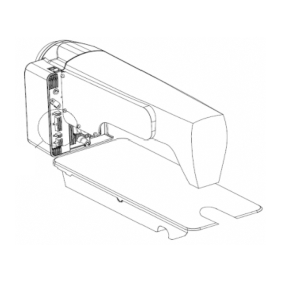
First, With self-tapping screws fastening the pedals①under the proper position of the platen
②.(direct drive servo motor ③and control box④has been fixed on the sewing machine head⑤).
Then the two ends of the pedal connecting rod⑥ are connected with the pedals① and the
bottom pedal⑦.
Fig.1-1 Direct drive machine controller installation diagram
第 1 页 共 16 页
Advertisement
Table of Contents

Summary of Contents for Powermax Tech AHE58-55
-
Page 1: Installation Instructions
1 Installation Instructions 1.1 Product specifications Product Type: AHE58-55; maximum motor speed: 5000 r / min; Supply Voltage: AC 220 ± 44 V; Power frequency: 50Hz/60Hz; Maximum output power: 550W; maximum motor torque: 3Nm. Pedal installation First, With self-tapping screws fastening the pedals①under the proper position of the platen... -
Page 2: Wiring And Grounding
:The footboard trys to ensure that the installation position is vertical rod pedals, the operator pedal is more comfortable and flexible. 1.3 Interface plug connections The pedals and the machine head of the connector plug are mounted to the corresponding position in the controller back of socket, the name of each socket shown in Figure 1-2. - Page 3 : All power lines, signal lines, ground lines, wiring not to be pressed into other objects or excessive distortion, to ensure safe use! 2 Operation Panel Instruction 2.1 Operation Panel Display Instruction 2.1.1 The operation panel composition Operation Panel is divided with two areas(See Fig2-1) :LCD display areas and key words area. Fig.2-1 Operation Panel 2.1.2 The LCD display The LCD display areas are position in middle of the whole operation panel.
- Page 4 End back tacking W seam Sewing segments Multi-seam index Numeric character display (pin number / Trigger function parameter) Footlifter after Automatic test trimming Clamp function Middle stop footlifter 2.2 The operation panel keys of description A description of each key operation panel shown in Table 2-2. Table 2-2 : Key Functions instruction Description Appearance...
-
Page 5: Operator Mode
Description Appearance Stitch compensation key:Start stitch compensation if press, stop stitch compensation if loose. Trimming key: Select/Cancel automatic trimming. The trimming status is displayed on top of LCD screen. Detailed see "3.1.5 trimming set. Press foot lifting key: Every effective pushed the key once; round with trimming after press foot lifting, sewing end press foot lifting and manual press foot lifting. - Page 6 is W sewing setup status. You may use keys and keys to choice needle in A area and set rang 1-99 stitches; use keys and keys to choice needle in B area and set rang 1-99 stitches. Press key, can be used to choice A B D segment, , use keys and keys to choice needle in B area and set rang 1-99...
-
Page 7: Technician Mode
repeat, the icon is lightened/ disappeared in LCD area. Whether it choice trimming that the icon is lightened or disappeared. 3.1.6 One-Shot-Sewing key key: select/non-select one-shot-sewing statues. The icon will light if select one-shot-sewing in LCD areas, press will disappear. 3.1.7 Stop position key key: select up/down stop position. - Page 8 Parameter Mode Rang Default Comment 0:Soft start only after trimming 1:Soft start after both trimming and stop 1 ~9 Soft start stitch number 100 ~800 Soft start speed System accelerate sensitivity ( D i r e c t d r i v e transmission can be set up to a large value ;...
- Page 9 Parameter Mode Rang Default Comment 2: Arithmetic Curve( the parameters [33] cooperate with use) Speed Speed Pedal forward angle Pedal forward angle ) 3: S curve (the operate control is very well, slow start after fast Speed Pedal forward angle Two segment controls the speed slope:mid turning point speed RPM(two segment of turning point speed),the parameter[30] set to 1 effective。...
- Page 10 Parameter Mode Rang Default Comment 2:Square root(Responding speed is fast, fast start after slow); Speed Pedal forward angle Pedal trimming position set, See 5-1.(the value is not higher 0 ~1024 than the parameter [35]) Press foot lifting, See 5-1. 0 ~1024 (the value is between[34]and[36].)...
- Page 11 Parameter Mode Rang Default Comment Special Running Mode setup: 0:operator select 1:simple sewing mode 0/1/2/ 2:calculate initial angle of motor (do not uninstall strap) 3:calculate motor/machine head run rate mode (synchronizer, do not uninstall strap) Torque boost up at low speed : 0—31 0:no action 1~31:31 levels Torque boost up...
- Page 12 Parameter Mode Rang Default Comment Trimming counting mode selection: 0: no counting 1: Counting up according to stitch number, after reaching set value then restart. 2: Counting down according to stitch number, after reaching set value then restart. 3: Counting up according to stitch number, after reaching set value, then motor should stop automatically, recounting should be restart by S4 [152.INI] =CRS or the button A on operation panel.
-
Page 13: Administrator Mode
3.3 Administrator mode Administrator mode is used for functions such as sewing machine head solenoid adjustment. 3.3.1 How to entre administrator mode keys to enter administrator mode in LCD PD Step 1:Under operator mode, press 0000 and then set the password 0000 to enter administrator mode. Step 2: The password is entered using keys and keys, then... - Page 14 Parameter Rang Mode Default Comment Clamp The end angles of tension release(r e l a t i v e d o w n 10 -359 mode position of angle, Need to greater than the system of parameters【11】) 1 - 999 Tension release solenoid start delay timeT1(ms)...
-
Page 15: Parameter Reset To Factory Settings
3.4 Monitor mode 3.4.1 How to enter monitor mode keys and During HMI idle, Press key, then press key, entry monitor mode. Use keys to switch to watch the parameters. About the monitor parameter, please refer the sheet 4, HMI will back to idle if no wheel or no press the key in regulates time. - Page 16 keys, LCD PD 0000; and then set the Step 1: Under operator mode, press password 0000 to enter technician mode. Step 2: The password is entered using keys and keys, then press key. If the password is correct, enter into the technician mode, or return to the technician mode.
Need help?
Do you have a question about the AHE58-55 and is the answer not in the manual?
Questions and answers