Advertisement
Advertisement
Troubleshooting

Related Manuals for Rohde & Schwarz ZNB8


Summary of Contents for Rohde & Schwarz ZNB8
- Page 1 ® R&S ZNB/ZNBT Vector Network Analyzers User Manual (;×éÍ2) 1173.9163.02 ─ 38...
- Page 2 ZNB4, 9 kHz to 4.5 GHz, 4 test ports, order no. 1311.6010.24 ● ® R&S ZNB8, 9 kHz to 8.5 GHz, 2 test ports, order no. 1311.6010.42 ● ® R&S ZNB8, 9 kHz to 8.5 GHz, 4 test ports, order no. 1311.6010.44 ●...
-
Page 3: Basic Safety Instructions
Basic Safety Instructions Always read through and comply with the following safety instructions! All plants and locations of the Rohde & Schwarz group of companies make every effort to keep the safety standards of our products up to date and to offer our customers the highest possible degree of safety. Our products and the auxiliary equipment they require are designed, built and tested in accordance with the safety standards that apply in each case. - Page 4 Basic Safety Instructions Symbol Meaning Symbol Meaning Caution ! Hot surface Alternating current (AC) Protective conductor terminal Direct/alternating current (DC/AC) To identify any terminal which is intended for connection to an external conductor for protection against electric shock in case of a fault, or the terminal of a protective earth Earth (Ground) Class II Equipment...
- Page 5 Basic Safety Instructions Operating states and operating positions The product may be operated only under the operating conditions and in the positions specified by the manufacturer, without the product's ventilation being obstructed. If the manufacturer's specifications are not observed, this can result in electric shock, fire and/or serious personal injury or death. Applicable local or national safety regulations and rules for the prevention of accidents must be observed in all work performed.
- Page 6 Basic Safety Instructions 6. The product may be operated only from TN/TT supply networks fuse-protected with max. 16 A (higher fuse only after consulting with the Rohde & Schwarz group of companies). 7. Do not insert the plug into sockets that are dusty or dirty. Insert the plug firmly and all the way into the socket provided for this purpose.
- Page 7 Basic Safety Instructions 2. Before you move or transport the product, read and observe the section titled "Transport". 3. As with all industrially manufactured goods, the use of substances that induce an allergic reaction (allergens) such as nickel cannot be generally excluded. If you develop an allergic reaction (such as a skin rash, frequent sneezing, red eyes or respiratory difficulties) when using a Rohde &...
- Page 8 Basic Safety Instructions 2. Adjustments, replacement of parts, maintenance and repair may be performed only by electrical experts authorized by Rohde & Schwarz. Only original parts may be used for replacing parts relevant to safety (e.g. power switches, power transformers, fuses). A safety test must always be performed after parts relevant to safety have been replaced (visual inspection, protective conductor test, insulation resistance measurement, leakage current measurement, functional test).
- Page 9 Instrucciones de seguridad elementales 3. If you use the product in a vehicle, it is the sole responsibility of the driver to drive the vehicle safely and properly. The manufacturer assumes no responsibility for accidents or collisions. Never use the product in a moving vehicle if doing so could distract the driver of the vehicle.
- Page 10 Instrucciones de seguridad elementales Además queda en la responsabilidad del usuario utilizar el producto en la forma debida. Este producto está destinado exclusivamente al uso en la industria y el laboratorio o, si ha sido expresamente autorizado, para aplicaciones de campo y de ninguna manera deberá ser utilizado de modo que alguna persona/cosa pueda sufrir daño.
- Page 11 Instrucciones de seguridad elementales Símbolo Significado Símbolo Significado Conexión a tierra El aparato está protegido en su totalidad por un aislamiento doble (reforzado) Conexión a masa Distintivo de la UE para baterías y acumuladores Más información en la sección "Eliminación/protección del medio ambiente", punto 1.
- Page 12 Instrucciones de seguridad elementales Estados operativos y posiciones de funcionamiento El producto solamente debe ser utilizado según lo indicado por el fabricante respecto a los estados operativos y posiciones de funcionamiento sin que se obstruya la ventilación. Si no se siguen las indicaciones del fabricante, pueden producirse choques eléctricos, incendios y/o lesiones graves con posible consecuencia de muerte.
- Page 13 Instrucciones de seguridad elementales integran productos sin interruptor en bastidores o instalaciones, se deberá colocar el interruptor en el nivel de la instalación. 5. No utilice nunca el producto si está dañado el cable de conexión a red. Compruebe regularmente el correcto estado de los cables de conexión a red.
- Page 14 Instrucciones de seguridad elementales 17. No utilice el producto en condiciones en las que pueda producirse o ya se hayan producido condensaciones sobre el producto o en el interior de éste, como p. ej. al desplazarlo de un lugar frío a otro caliente.
- Page 15 Instrucciones de seguridad elementales pueden causar perturbaciones radioeléctricas en entornos residenciales debido a posibles perturbaciones guiadas o radiadas. En este caso, se le podrá solicitar al operador que tome las medidas adecuadas para eliminar estas perturbaciones. Aparato de clase B: Aparato adecuado para su uso en entornos residenciales, así...
- Page 16 Instrucciones de seguridad elementales 8. En caso de devolver baterías de litio a las filiales de Rohde & Schwarz, debe cumplirse las normativas sobre los modos de transporte (IATA-DGR, código IMDG, ADR, RID). Transporte 1. El producto puede tener un peso elevado. Por eso es necesario desplazarlo o transportarlo con precaución y, si es necesario, usando un sistema de elevación adecuado (p.
- Page 17 Customer Support Technical support – where and when you need it For quick, expert help with any Rohde & Schwarz equipment, contact one of our Customer Support Centers. A team of highly qualified engineers provides telephone support and will work with you to find a solution to your query on any aspect of the operation, programming or applications of Rohde &...
-
Page 18: Table Of Contents
® Contents R&S ZNB/ZNBT Contents 1 Documentation Map................13 2 Release Notes for Firmware V2.86............. 14 3 Getting Started..................15 Putting the Analyzer into Operation................15 3.1.1 Unpacking and Checking the Instrument..............15 3.1.2 Positioning the Instrument.....................16 3.1.3 Bench Top Operation....................17 3.1.4 Operation in a 19"... -
Page 19: Table Of Contents
® Contents R&S ZNB/ZNBT 4 Concepts and Features............... 75 Basic Concepts......................75 4.1.1 Global (Persistent) Settings..................75 4.1.2 Recall Sets........................76 4.1.3 Traces, Channels and Diagrams...................76 4.1.4 Sweep Control.......................78 4.1.5 Data Flow........................85 Screen Elements......................87 4.2.1 Display Elements of a Diagram..................87 4.2.2 Dialogs.......................... -
Page 20: Table Of Contents
® Contents R&S ZNB/ZNBT 4.6.1 Offset Parameters....................... 175 4.6.2 Embedding and Deembedding..................181 Optional Extensions and Accessories..............192 4.7.1 Additional Test Ports (R&S ZNBT only)..............192 4.7.2 Time Domain Analysis....................193 4.7.3 Mixer and Frequency Conversion Measurements............203 4.7.4 Receiver Bandwidth 10 MHz..................211 4.7.5 Frequency Resolution 1 mHz..................212 4.7.6... -
Page 21: Table Of Contents
® Contents R&S ZNB/ZNBT Cal Softtool........................ 257 5.4.1 Start Cal Tab....................... 257 5.4.2 Cal Devices Tab......................319 5.4.3 Pwr Cal Settings Tab....................332 5.4.4 Use Cal Tab........................ 338 Channel Config Softtool................... 344 5.5.1 Channels Tab......................344 5.5.2 Port Config Tab......................359 5.5.3 Mode Tab........................ -
Page 22: Table Of Contents
® Contents R&S ZNB/ZNBT 5.9.5 Z←Sij Tab........................456 5.9.6 Y←Sij Tab........................457 5.9.7 Y-Z-Params Tab......................459 5.9.8 Imbal. CMRR Tab....................... 461 5.9.9 Stability Tab........................ 463 5.9.10 Power Sensor Tab...................... 464 5.9.11 DC Tab........................466 5.10 Format Softtool......................469 5.11 Scale Softtool......................475 5.11.1 Scale Values Tab...................... -
Page 23: Table Of Contents
® Contents R&S ZNB/ZNBT 5.14.6 Target Search Tab...................... 542 5.14.7 Bandfilter Tab......................545 5.14.8 Set by Marker Tab.......................549 5.14.9 Info Field Tab......................550 5.15 File Softtool....................... 551 5.15.1 Recall Sets Tab......................551 5.15.2 Favorites Tab......................555 5.15.3 Print Tab........................556 5.15.4 Trace Data Tab......................557 5.15.5 More Tab........................557 5.16... -
Page 24: Table Of Contents
® Contents R&S ZNB/ZNBT 6.1.3 Switchover to Remote Control..................643 6.1.4 Combining Manual and Remote Control..............646 Messages........................647 6.2.1 Device Messages (Commands and Device Responses)..........647 6.2.2 SCPI Command Structure and Syntax................647 6.2.3 SCPI Parameters......................651 Basic Remote Control Concepts................653 6.3.1 Traces, Channels, and Diagram Areas............... -
Page 25: Table Of Contents
® Contents R&S ZNB/ZNBT 7.3.2 CALCulate Commands....................679 7.3.3 CONFigure Commands....................844 7.3.4 CONTrol Commands....................851 7.3.5 DIAGnostic Commands....................875 7.3.6 DISPlay Commands....................877 7.3.7 FORMat Commands....................902 7.3.8 HCOPy Commands.....................903 7.3.9 INITiate Commands....................908 7.3.10 INSTrument Commands..................... 910 7.3.11 MEMory........................912 7.3.12 MMEMory Commands....................913 7.3.13 OUTPut Commands....................952 7.3.14... -
Page 26: Table Of Contents
® Contents R&S ZNB/ZNBT Errors during Firmware Operation................ 1245 9.1.1 Asynchronous Errors....................1246 9.1.2 Errors during Measurement..................1246 Errors during Firmware Installation/Update............1247 Obtaining Technical Support................. 1248 10 Annexes.................... 1250 10.1 Administrative Tasks....................1250 10.1.1 Windows Operating System..................1250 10.1.2 Firmware Update.......................1251 10.2 Interfaces and Connectors..................1251 10.2.1... - Page 27 ® Contents R&S ZNB/ZNBT User Manual 1173.9163.02 ─ 38...
-
Page 28: Documentation Map
® Documentation Map R&S ZNB/ZNBT 1 Documentation Map The R&S ZNB/ZNBT documentation is delivered as a printed Getting Started guide and a documentation CD-ROM providing the complete user documentation. In addi- tion, a help system is embedded in the instrument. Getting Started Guide The Getting Started guide describes everything that is needed to put the instrument into operation and helps you to get familiar with the R&S ZNB/ZNBT. -
Page 29: Release Notes For Firmware V2.86
® Release Notes for Firmware V2.86 R&S ZNB/ZNBT 2 Release Notes for Firmware V2.86 Version 2.86 of the R&S ZNB/ZNBT firmware provides the following changes: New features ● Support of additional test ports 17 to 24 for R&S ZNBT20 (options R&S ZNBT20- B120 and -B124) Chapter 4.7.1, "Additional Test Ports (R&S ZNBT only)",... -
Page 30: Getting Started
® Getting Started R&S ZNB/ZNBT Putting the Analyzer into Operation 3 Getting Started 3.1 Putting the Analyzer into Operation This section describes the basic steps to be taken when setting up the analyzer for the first time. Simple measurement examples are provided in Chapter 3.4, "Performing Measure- ments", on page 65;... -
Page 31: Positioning The Instrument
® Getting Started R&S ZNB/ZNBT Putting the Analyzer into Operation Packing material Retain the original packing material. If the instrument needs to be transported or ship- ped later, you can use the material to protect the control elements and connectors. Risk of injury and damage during transportation and shipment Insufficient protection against mechanical and electrostatic effects during transportation and shipment can damage the instrument. -
Page 32: Bench Top Operation
® Getting Started R&S ZNB/ZNBT Putting the Analyzer into Operation 3.1.3 Bench Top Operation If the analyzer is operated on a bench top, the surface should be flat. The instrument can be used in horizontal or vertical position, standing on its feet, or with the support feet on the bottom expanded. -
Page 33: Starting The Analyzer And Shutting Down
® Getting Started R&S ZNB/ZNBT Putting the Analyzer into Operation ► Connect the network analyzer to the AC power source using the AC power cable delivered with the instrument. The maximum power consumption and the typical power consumption of the individual analyzer models are listed in the data sheet. -
Page 34: Standby And Ready State
® Getting Started R&S ZNB/ZNBT Putting the Analyzer into Operation Risk of data loss It is strongly recommended to switch the analyzer to standby state before disconnect- ing it from the AC supply. If you set the power switch to 0 while the VNA application is still running, you will lose the current settings. - Page 35 ® Getting Started R&S ZNB/ZNBT Putting the Analyzer into Operation For the R&S ZNBT an external monitor and mouse are required for local operation. The R&S ZNB can be fully controlled by tapping the touchscreen and front panel keys. 3.1.9.1 Connecting a Monitor A standard monitor can be connected to the DVI-D connector of the R&S ZNB/ZNBT.
- Page 36 ® Getting Started R&S ZNB/ZNBT Putting the Analyzer into Operation ® To access Windows , press the Windows key on the front panel (R&S ZNB only) or on the external keyboard. 3.1.9.4 Connecting a Printer A printer can be connected to any of the USB connectors. After successful installation it can safely be disconnected and reconnected even during measurements.
-
Page 37: Minimizing The Vna Application
® Getting Started R&S ZNB/ZNBT Putting the Analyzer into Operation The IP address information is shown in the "SETUP > Remote Settings" softtool panel. For the R&S ZNBT it is also shown on the Mini display. 3.1.9.6 Connecting an USB Cable for Remote Control Instruments equipped with controller LPW11 can also be remote controlled via USB. -
Page 38: Changing The Screen Resolution (R&S Znbt)
® Getting Started R&S ZNB/ZNBT Putting the Analyzer into Operation After a software update the VNA application is started with a maximized window again. Moreover, if a second VNA application is started after a first, minimized application, this will cause the first application to appear in the foreground. 3.1.11 Changing the Screen Resolution (R&S ZNBT) In case the R&S ZNBT fails to properly adjust the display resolution when an external monitor is connected, proceed as follows:... -
Page 39: Remote Operation In A Lan
® Getting Started R&S ZNB/ZNBT Putting the Analyzer into Operation c) Change the display "Resolution" to the desired value by dragging the slider; click "OK" and confirm the modified settings ("Keep Changes") 3.1.12 Remote Operation in a LAN A LAN connection is used to integrate the analyzer into a home/company network. This offers several applications, e.g.: ●... - Page 40 ® Getting Started R&S ZNB/ZNBT Putting the Analyzer into Operation Manual TCP/IP configuration If your network does not support DHCP, or if you choose to disable dynamic TCP/IP configuration, you must assign valid address information before you connect the ana- lyzer to the LAN.
- Page 41 ® Getting Started R&S ZNB/ZNBT Putting the Analyzer into Operation Figure 3-1: Windows 7 User Account Control dialog 6. In the "Local Area Connection Properties" dialog opened, select "Internet Protocol Version 4 (TCP/IPv4) > Properties" and enter the IP address information, e.g.: User Manual 1173.9163.02 ─...
- Page 42 ® Getting Started R&S ZNB/ZNBT Putting the Analyzer into Operation 3.1.12.2 Remote Desktop Connection ® Remote Desktop is a Windows application which you can use to access and control the analyzer from a remote computer through a LAN connection. While the measure- ment is running, the analyzer screen contents are displayed on the remote computer, and Remote Desktop provides access to all of the applications, files, and network resources of the analyzer.
-
Page 43: Instrument Tour
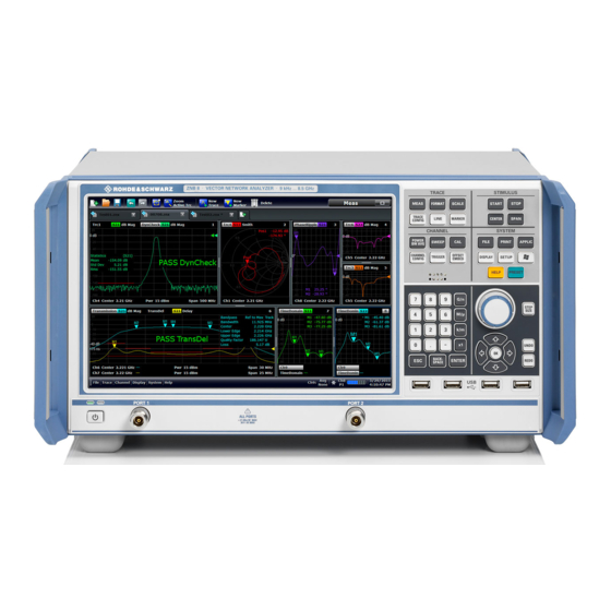
® Getting Started R&S ZNB/ZNBT Instrument Tour Some actions require a different firewall configuration, e.g.: ● To transfer data with other hosts in the LAN, you have to allow "File and Printer Sharing". To change the firewall settings proceed as follows: ®... - Page 44 Getting Started R&S ZNB/ZNBT Instrument Tour Figure 3-2: R&S ZNB8 with two ports 3.2.1.1 Touchscreen The analyzer is equipped with a 12.1'' XGA color touchscreen. The touchscreen pres- ents all measurement results, mostly in the form of diagrams. Besides, all instrument functions can be accessed and operated by tapping the control elements on the touch- screen.
- Page 45 ® Getting Started R&S ZNB/ZNBT Instrument Tour Screen saver The screen saver function of the operating system can be used to switch off the display if the analyzer receives no command for a selectable period of time. The display is switched on again if any front panel key is pressed.
- Page 46 ® Getting Started R&S ZNB/ZNBT Instrument Tour The SYSTEM keys provide general system settings. ● ® FILE provides standard Windows functions used to create, save, recall or print recall sets, to copy the active screen and to shut down the application. ●...
- Page 47 ® Getting Started R&S ZNB/ZNBT Instrument Tour – Confirm selections and entries made and close dialogs (equivalent to the "OK" button). – Compress or expand menus or the Help table of contents ● BACKSPACE deletes the last character before the cursor position or the selected character sequence or numeric value.
- Page 48 The test ports and four USB connectors are located on the front panel of the R&S ZNB. Test Ports Numbered connectors: ● type N (7 mm, female) for R&S ZNB4 and R&S ZNB8 ● PC (3.5 mm, male) for R&S ZNB20 ●...
-
Page 49: Front Panel R&S Znbt
® Getting Started R&S ZNB/ZNBT Instrument Tour The USB ports can be used to connect ● external PC accessories such as mouse or other pointing devices, a keyboard, printer or external storage device (USB stick, CD-ROM drive etc.) ● external measurement equipment such as a calibration unit, power meter, signal generator or switch matrix The length of passive connecting USB cables should not exceed 1 m. - Page 50 ® Getting Started R&S ZNB/ZNBT Instrument Tour 3.2.2.1 Test Ports Numbered test port connectors: ● For the R&S ZNBT8 these are type N female connectors. Depending on the equip- ped options there are 4, 8, 12, 16, 20 or 24 test ports. ●...
-
Page 51: Rear Panel R&S Znb
® Getting Started R&S ZNB/ZNBT Instrument Tour – Error <error code>: severe errors (e.g. FW boot errors, HW errors) ● Control mode: – "Local": manual interaction (e.g. via Remote Desktop) – "Remote": remote control (using a script) via a LAN or GPIB connection USB Connectors Two USB 2.0 connectors of type A (master USB) are provided on the front panel. - Page 52 ® Getting Started R&S ZNB/ZNBT Instrument Tour 9 10 Figure 3-4: R&S ZNB rear view Table 3-1: Rear panel connectors available on all instruments Index Label Description (Power Power on / off switch, see Chapter 3.1.7, "Starting the Analyzer and Shutting Down", I/O) on page 18...
- Page 53 ® Getting Started R&S ZNB/ZNBT Instrument Tour Index Label Description REF OUT BNC output for the internal reference frequency of the R&S ZNB. Use this connector to synchronize other instruments to the analyzer. Chapter 5.19.3, "Remote Settings Tab", on page 617. REF IN BNC input for an external reference frequency.
-
Page 54: Rear Panel R&S Znbt
® Getting Started R&S ZNB/ZNBT Instrument Tour Input levels, EMC The maximum input levels and voltages of the input connectors at the front and rear panel must not be exceeded. Use double shielded cables at the BNC rear panel connectors (EXT. TRIGGER OUT, EXT TRIGGER IN, REF OUT, REF IN) and match signals with 50 Ω... - Page 55 ® Getting Started R&S ZNB/ZNBT Instrument Tour Index Label Description Two additional type A USB host connectors, similar functionality as the type a host USB / connectors on the front panel (see "USB Connectors" on page 36). USB Host ● USB 2.0, labeled "USB"...
-
Page 56: Operating The Instrument
® Getting Started R&S ZNB/ZNBT Operating the Instrument Table 3-4: Optional rear panel connectors Index Label Description DC INPUT Option R&S ZNBT-B81"DC Inputs" provides four BNC inputs for DC measurements (adjustable to different voltage ranges). Chapter 5.9.11, "DC Tab", on page 466. Device This slot can be equipped with option R&S ZNBT-B12, providing a PCIe and a Direct Control... -
Page 57: Manual Operation
® Getting Started R&S ZNB/ZNBT Operating the Instrument 3.3.1 Manual Operation The analyzer functions are arranged in tabbed softtool panels and dialogs. The keys on the front panel (R&S ZNB only) or the on-screen "Hard Key Panel" open the most frequently used panels. - Page 58 ® Getting Started R&S ZNB/ZNBT Operating the Instrument Using (Virtual) Hard Keys To access an instrument function 1. Press a (virtual) key, e.g. the MEAS key in the TRACE panel. The corresponding softtool panel expands at the current docking position. 2.
- Page 59 ® Getting Started R&S ZNB/ZNBT Operating the Instrument Using the menu bar The menu bar at the bottom of the application screen provides an alternative access to all instrument functions. To repeat the "Z←S11" setting described above, ► Select "Trace > Meas > Z←Sij > Z←S11". The diagram immediately shows the result of your setting.
- Page 60 ® Getting Started R&S ZNB/ZNBT Operating the Instrument 2. Select "S-Parameter" to open the "Meas > S-Params" softtool tab. 3. Select "Z←Sij > Z←S11". User Manual 1173.9163.02 ─ 38...
-
Page 61: Control Elements Of The Screen
® Getting Started R&S ZNB/ZNBT Operating the Instrument 3.3.2 Control Elements of the Screen The main window of the analyzer provides all control elements for the measurements and contains the diagrams for the results. There are several alternative ways for accessing an instrument function: ●... - Page 62 ® Getting Started R&S ZNB/ZNBT Operating the Instrument These methods are described in more detail in the following sections. For further reference: ● Refer to Chapter 4.2.1, "Display Elements of a Diagram", on page 87 to obtain information about the results in the diagram. ●...
- Page 63 ® Getting Started R&S ZNB/ZNBT Operating the Instrument You can display or hide the title bar using "SYSTEM > DISPLAY > View Bar" or "APPLIC > External Tools". The title bar is displayed together with the taskbar across the bottom of the screen which you can use to change between the VNA application and external tools.
- Page 64 ® Getting Started R&S ZNB/ZNBT Operating the Instrument Figure 3-6: Scale softtool A softtool consists of a title area with a close/re-open icon and a tabbed panel below it. The title area remains displayed when the softtoool panel is closed, which allows you to re-open closed softtools at any time.
- Page 65 ® Getting Started R&S ZNB/ZNBT Operating the Instrument ● The "Display" menu provides all display settings and the functions for activating, modifying and arranging different diagrams. ● The "Applications" menu gives access to applications and tools that extend the functionality of the analyzer firmware. ●...
- Page 66 ® Getting Started R&S ZNB/ZNBT Operating the Instrument function keys open a related softtool. For a short description refer to section Chap- ter 3.2.1.2, "Function Keys", on page 30. The keys of the hardkey panel open a particular tab of the softtool panel providing rela- ted control elements.
-
Page 67: Working With Dialogs
® Getting Started R&S ZNB/ZNBT Operating the Instrument ● the Redefined S-parameters symbol (if the physical ports have been redefined) (see Chapter 5.19.5.2, "Define Physical Ports Dialog", on page 629) ● the switch matrix status symbol, if a switch matrix is connected to the analyzer (See Chapter 4.7.20, "External Switch Matrices",... -
Page 68: Handling Diagrams, Traces, And Markers
® Getting Started R&S ZNB/ZNBT Operating the Instrument All dialogs are operated in a similar way. ● To open a dialog, select a softtool button with three dots behind its labeling (e.g. "Start Cal (Manual) ..."). ● Use the "Transparency" function to obtain a transparent dialog which you can con- trol while viewing the underlying traces and display elements. - Page 69 ® Getting Started R&S ZNB/ZNBT Operating the Instrument 2. Select the sector, depending on whether you want to display the new trace in the existing diagram, or whether you want to add a new diagram. 3. In the dialog box that is opened when you release the "New Trace" icon, select an S-parameter to display.
- Page 70 ® Getting Started R&S ZNB/ZNBT Operating the Instrument Alternative control elements The "TRACE > Trace Config" softtool tab provides more functions for trace handling. The "DISPLAY > Display > Diagram" softtool tab provides functions for efficient dia- gram handling. To add a trace for an arbitrary measured quantity (e.g. a ratio, wave, impedance, or admittance parameter), you can open the tabs of the "TRACE >...
- Page 71 ® Getting Started R&S ZNB/ZNBT Operating the Instrument Markers, traces, diagram areas, and other display elements are most conveniently deleted using the "Delete" icon in the toolbar above the diagram area. ● To delete a single marker, drag it into vertical direction to release it from the trace and drop it onto the "Delete"...
-
Page 72: Entering Data
® Getting Started R&S ZNB/ZNBT Operating the Instrument Screen element Action Drag and drop... Reset / suspend "Graphic Zoom" element in additional trace line --> "Delete" icon; see Chap- graphic zoom ter 3.3.6.1, "Using the Graphic Zoom", on page 60 Marker Create "New Marker"... - Page 73 ® Getting Started R&S ZNB/ZNBT Operating the Instrument ● Use "." and "-" to enter a decimal point or change the sign of the value. ● Use "G/n", "M/μ", "k/m", or "x1" to multiply the entered value with factors of (-)9 , 10 (-)6...
- Page 74 ® Getting Started R&S ZNB/ZNBT Operating the Instrument 2. Use the buttons in the numeric keypad to compose the numeric input value. 3. If desired, select a "Stepsize" and use the cursor up/down buttons to increment/ decrement the current value. If a marker is active, you can also set the numeric value to the current marker value ("Set to Marker").
-
Page 75: Scaling Diagrams
® Getting Started R&S ZNB/ZNBT Operating the Instrument 2. Click a sequence of characters and "Enter" to apply your selection and close the keyboard. ® 3.3.5.4 Using the Windows On-Screen Keyboard ® The Windows on-screen keyboard allows you to enter characters, in particular letters, even if an input field cannot call up the analyzer's own on-screen keyboard. - Page 76 ® Getting Started R&S ZNB/ZNBT Operating the Instrument The zoomed view shows the selected area, scaled in both horizontal and vertical direction. In general, the zoom window covers only part of the sweep range; the distance between the displayed sweep points increases. The reduced sweep range is displayed in the additional trace lines at the bottom of the diagram.
- Page 77 ® Getting Started R&S ZNB/ZNBT Operating the Instrument Alternative settings The "TRACE > Scale > Zoom" softtool panel provides numeric input fields where you can refine the displayed zoom range. To zoom the stimulus range and change the sweep point spacing so that the number of displayed sweep points is maintained, use "STIMULUS >...
- Page 78 ® Getting Started R&S ZNB/ZNBT Operating the Instrument ● Use the "Set by Marker" functions ("TRACE > MARKER > Marker Funct"; see Chapter 3.3.6.6, "Set by Marker", on page 63). 3.3.6.4 Auto Scale The "Auto Scale" function adjusts the scale divisions and the reference value so that the entire trace fits into the diagram.
- Page 79 ® Getting Started R&S ZNB/ZNBT Operating the Instrument To set the sweep range use one of the following methods. Define "Start" and "Stop" values: 1. Create two normal markers, e.g. the markers Mkr 1 (M1) and Mkr 2 (M2), and place them to the desired start and stop values of the sweep range.
-
Page 80: Performing Measurements
® Getting Started R&S ZNB/ZNBT Performing Measurements You can also use marker values in the "Numeric Editor" dialog; see Chapter 3.3.5.2, "Using the Numeric Editor", on page 58. 3.3.6.7 Enlarging a Diagram The analyzer provides different tools for customizing the contents and size of the dia- grams: ●... -
Page 81: Transmission S-Parameter Measurement
® Getting Started R&S ZNB/ZNBT Performing Measurements 4. Define the sweep range 5. Adjust the receiver and source settings (measurement bandwidth, source power) 6. Perform a calibration 3.4.1 Transmission S-Parameter Measurement In a transmission measurement, the analyzer transmits a stimulus signal to the input port of the device under test (DUT) and measures the transmitted wave at the DUT's output port. - Page 82 ® Getting Started R&S ZNB/ZNBT Performing Measurements 1. Connect the DUT between test ports 1 and 2 of the network analyzer as shown above. 2. Proceed as described in Chapter 3.1.7, "Starting the Analyzer and Shutting Down", on page 18, to switch on the instrument and start the VNA application. 3.
- Page 83 ® Getting Started R&S ZNB/ZNBT Performing Measurements at port 2. The stimulus signal from the analyzer port no. 2 is not needed except for some calibration types. By default the frequency range of the analyzer is selected as sweep range is. To gain some more insight into the transmission characteristics of your DUT you can select a smaller sweep range.
- Page 84 ® Getting Started R&S ZNB/ZNBT Performing Measurements The following example requires a calibration kit with a male Through standard with known transmission characteristics for the related test port connector type and gender. With a single Through, it is possible to perform a transmission normalization, compen- sating for a frequency-dependent attenuation and phase shift in the signal paths.
- Page 85 ® Getting Started R&S ZNB/ZNBT Performing Measurements 6. The "Calibration" dock widget indicates the calibration standards to be measured. Select "Through (mm)" to initiate the measurement of the connected Through stan- dard. User Manual 1173.9163.02 ─ 38...
- Page 86 ® Getting Started R&S ZNB/ZNBT Performing Measurements The analyzer performs a calibration sweep for the measured quantity S . The magnitude and phase of the result is displayed in two diagrams, together with the expected typical result for a through standard. The similarity of real and expected traces indicates that the Through standard has been properly connected.
- Page 87 ® Getting Started R&S ZNB/ZNBT Performing Measurements Refer to Chapter 4.2.3, "Trace Formats", on page 102 to learn more about the dia- gram properties. 3.4.1.5 Saving and Printing Data The analyzer provides standard functions for saving measurement settings and for saving or printing the results.
-
Page 88: Reflection S-Parameter Measurement
® Getting Started R&S ZNB/ZNBT Performing Measurements 3.4.2 Reflection S-Parameter Measurement In a reflection measurement, the analyzer transmits a stimulus signal to the input port of the device under test (DUT) and measures the reflected wave. A number of trace formats allow you to express and display the results, depending on what you want to learn from the data. - Page 89 ® Getting Started R&S ZNB/ZNBT Performing Measurements You can also use the basic transmission test setup, e.g. if you want to measure reflection and transmission parameters in parallel. ● The analyzer provides special calibration types for reflection measurements. Use the calibration wizard and select an appropriate type. The full n-port calibration types (TOSM, UOSM, TNA ...) will correct the system errors for all transmission and reflection S-parameters.
-
Page 90: Concepts And Features
® Concepts and Features R&S ZNB/ZNBT Basic Concepts 4 Concepts and Features The following chapter provides an overview of the analyzer's capabilities and their use. This includes a description of the basic concepts that the analyzer uses to organize, process and display measurement data, of the screen contents, possible measured quantities, calibration methods and typical test setups. -
Page 91: Recall Sets
® Concepts and Features R&S ZNB/ZNBT Basic Concepts ● Connector types ● Cal pool data including system error correction and power correction data ● Directories for trace data, limit lines, calibration data etc. ● Color schemes and printer settings ● System configurations, to be accessed via SYSTEM –... - Page 92 ® Concepts and Features R&S ZNB/ZNBT Basic Concepts 4.1.3.1 Trace Settings The trace settings specify the mathematical operations used in order to obtain traces from the measured or stored data. They can be divided into several main groups: ● Selection of the measured quantity (S-parameters, wave quantities, ratios, impe- dances,...) ●...
-
Page 93: Sweep Control
® Concepts and Features R&S ZNB/ZNBT Basic Concepts 4.1.3.3 Active and Inactive Traces and Channels A window can display several diagrams simultaneously, each with a variable number of traces. One of these traces is active at each time. The active trace is highlighted in the trace list on top of the active diagram (Trc4 in the figure below): When a trace is selected in the diagram area, it becomes the active trace. - Page 94 ® Concepts and Features R&S ZNB/ZNBT Basic Concepts After changing the channel settings or selecting another measured quantity, the ana- lyzer needs some time to initialize the new sweep. This preparation period increases with the number of points and the number of partial measurements involved. It indica- ted in the status bar: All analyzer settings can still be changed during sweep initialization.
- Page 95 ® Concepts and Features R&S ZNB/ZNBT Basic Concepts Use the "Alternated" mode to increase the accuracy of measurements on DUTs with long level settling times (e.g. quartzes, SAW filters). To measure DUTs with short set- tling times and obtain a trace from the beginning of the sweep, use "Chopped" mode. In "Auto"...
- Page 96 ® Concepts and Features R&S ZNB/ZNBT Basic Concepts ● For analyzers with Internal Second Source, in order to reduce "crosstalk" between the DUTs a frequency offset can be applied between the corresponding port groups (see "Parallel Measurements with Frequency Offset" on page 82).
- Page 97 ® Concepts and Features R&S ZNB/ZNBT Basic Concepts Example: DUT 1 (two ports): drive port order 1,2 DUT 2 (two ports): drive port order 2,1 DUT 3 (four ports): drive port order 3,4,1,2 DUT 4 (four ports): drive port order 4,3,2,1 With "port x-y"...
- Page 98 ® Concepts and Features R&S ZNB/ZNBT Basic Concepts ● Please note that in parallel measurement with frequency offset the firmware uses a modified IF as compared to measurements not using this mode. Because this modified IF requires a special calibration it is essential to perform the Calibration with the same Frequency Offset settings as for the actual measurement;...
- Page 99 ® Concepts and Features R&S ZNB/ZNBT Basic Concepts The stimulus hardkeys define the fixed stimulus frequency ("CW Frequency") and the "Number of Points" of the measurement. The other sweep parameters (e.g. the "Sweep Time") are set via CHANNEL – SWEEP > "Sweep Params". ●...
-
Page 100: Data Flow
® Concepts and Features R&S ZNB/ZNBT Basic Concepts If on the other hand the swept mode is not used although it was selected, the underly- ing reason is displayed in an information popup: ● The specifications of the data sheet are stated for stepped mode; in swept mode they are not guaranteed ●... - Page 101 ® Concepts and Features R&S ZNB/ZNBT Basic Concepts Figure 4-1: Data Flow User Manual 1173.9163.02 ─ 38...
-
Page 102: Screen Elements
® Concepts and Features R&S ZNB/ZNBT Screen Elements 4.2 Screen Elements This section describes manual operation of the analyzer, including trace settings, markers and diagrams. For a description of the different quantities measured by the instrument refer to Chapter 4.3, "Measurement Results", on page 110. - Page 103 ® Concepts and Features R&S ZNB/ZNBT Screen Elements 4.2.1.1 Title An optional title across the top of the diagram may be used for a brief description of the diagram contents. Select SYSTEM – DISPLAY > "Diagram" > "Title" to enter the diagram title and "Show Title"...
- Page 104 ® Concepts and Features R&S ZNB/ZNBT Screen Elements of the triangle can be changed in order to modify the diagram scale and shift the trace vertically. ● Measured quantity (for the active trace): The measured quantity is indicated in the trace list;...
- Page 105 ® Concepts and Features R&S ZNB/ZNBT Screen Elements ● The measured quantity (e.g. an S-parameter or a ratio) appears on a colored background. The source port for wave quantities and ratios is indicated in brackets. ● The format section shows how the measured data is presented in the graphical display.
- Page 106 ® Concepts and Features R&S ZNB/ZNBT Screen Elements Example: The following context menu is assigned to the measured quantity section in the trace list: A label "Cal Off" appears at the end of the trace line if the system error correction no longer applies to the trace.
- Page 107 ® Concepts and Features R&S ZNB/ZNBT Screen Elements ● A delta marker ("DeltaM1, DeltaM2...") indicates the coordinates relative to the ref- erence marker. A special set of markers M1 to M4 is provided for bandfilter search mode. The most common tasks to be performed with markers can be achieved using the "Marker"...
- Page 108 ® Concepts and Features R&S ZNB/ZNBT Screen Elements The info field contains the following information: ● "M1, M2..." denote the marker numbers. Markers are displayed with the same color as the associated trace. ● The marker coordinates are expressed in one of the marker formats selected via TRACE –...
- Page 109 ® Concepts and Features R&S ZNB/ZNBT Screen Elements Marker Frmt" ), or formatted individually (TRACE > MARKER > "Marker Props" > "Marker Format"). The available marker formats are defined for all measured quantities and trace formats (see Chapter 4.2.3.3, "Measured Quantities and Trace Formats", on page 109).
- Page 110 ® Concepts and Features R&S ZNB/ZNBT Screen Elements The delay aperture is defined in the TRACE > FORMAT softtool. An impedance Z is represented as Z = R + jX, the corresponding admittance as Y = 1/Z = G + jB. For X ≥ 0 we have an inductance L = X/ω, for X < 0 we have a capaci- tance C = 1/(ωX), where ω...
- Page 111 ® Concepts and Features R&S ZNB/ZNBT Screen Elements ● Trace segments with a shape that is characteristic for bandpass or bandstop filters (bandfilter search); see "Bandfilter Search" on page 96. When the search is activated, the active marker is moved to the (next) point that meets the search criteria.
- Page 112 ® Concepts and Features R&S ZNB/ZNBT Screen Elements ● "Lower Edge" is the closest frequency below the maximum (or minimum), where the trace value is equal to the maximum (minimum) value minus (plus) n dB. ● "Upper Edge" is the closest frequency above the maximum (or minimum), where the trace value is equal to the maximum (minimum) value minus (plus) n dB.
- Page 113 ® Concepts and Features R&S ZNB/ZNBT Screen Elements ● The measurement mode identifier section (optional) indicates a special test mode of the channel, e.g. the measurement at arbitrary port frequencies ("Arb Port n"). ● Start indicates the lowest value of the sweep variable (e.g. the lowest frequency measured), corresponding to the left edge of a Cartesian diagram.
-
Page 114: Dialogs
® Concepts and Features R&S ZNB/ZNBT Screen Elements Example: The following context menu is assigned to the channel name section in the channel list: The functions of the context menu can also be called using the menu bar or the related softtool panels. - Page 115 ® Concepts and Features R&S ZNB/ZNBT Screen Elements In most dialogs, however, it is possible to cancel an erroneous input before it takes effect. The settings in such dialogs must be confirmed explicitly. The two types of dialogs are easy to distinguish: ●...
- Page 116 ® Concepts and Features R&S ZNB/ZNBT Screen Elements Tip: The "Open" dialog is used to open various file types (cal kit data, limit lines, sweep segment lists, ...). Depending on its use, the dialog is opened with different captions, file locations and file type filters. File locations (directories) are remembered when the dialog is closed.
-
Page 117: Trace Formats
® Concepts and Features R&S ZNB/ZNBT Screen Elements 4.2.3 Trace Formats A trace format defines how a trace is represented in a diagram. The R&S ZNB/ZNBT supports the following trace formats: ● Cartesian Trace Formats "dB Mag" , "Phase" , "SWR" , "Unwr Phase" , "Lin Mag" , "Real"... - Page 118 ® Concepts and Features R&S ZNB/ZNBT Screen Elements Figure 4-2: S11 trace in dB Mag format: sweep type Lin Freq (top) and Log Freq (bottom) Conversion of Complex to Real Quantities Among the measured quantities the R&S ZNB/ZNBT supports, only "Stability" factors, "Power Sensor"...
- Page 119 ® Concepts and Features R&S ZNB/ZNBT Screen Elements An extended range of formats and conversion formulas is available for markers. To convert any point on a trace, create a marker and select the appropriate marker format. Marker and trace formats can be selected independently. 4.2.3.2 Complex Trace Formats Complex trace formats assign a complex response to the stimulus value (frequency,...
- Page 120 ® Concepts and Features R&S ZNB/ZNBT Screen Elements Example: Reflection coefficients in polar diagrams If the measured quantity is a complex reflection coefficient (S etc.), then the cen- ter of the polar diagram corresponds to a perfect load Z at the input test port of the DUT (no reflection, matched input), whereas the outer circumference (|S | = 1) repre- sents a totally reflected signal.
- Page 121 ® Concepts and Features R&S ZNB/ZNBT Screen Elements Smith chart construction In a Smith chart, the impedance plane is reshaped so that the area with positive resist- ance is mapped into a unit circle. The basic properties of the Smith chart follow from this construction: ●...
- Page 122 ® Concepts and Features R&S ZNB/ZNBT Screen Elements According to the two equations above, the graphical representation in a Smith chart has the following properties: ● Real reflection coefficients are mapped to real impedances (resistances). ● The center of the Γ plane (Γ = 0) is mapped to the reference impedance Z whereas the circle with |Γ| = 1 is mapped to the imaginary axis of the Z plane.
- Page 123 ® Concepts and Features R&S ZNB/ZNBT Screen Elements Inverted Smith chart construction The inverted Smith chart is point-symmetric to the Smith chart: The basic properties of the inverted Smith chart follow from this construction: ● The central horizontal axis corresponds to zero susceptance (real admittance). The center of the diagram represents Y/Y = 1, where Y is the reference admittance of...
- Page 124 ® Concepts and Features R&S ZNB/ZNBT Screen Elements According to the two equations above, the graphical representation in an inverted Smith chart has the following properties: ●...
-
Page 125: Measurement Results
® Concepts and Features R&S ZNB/ZNBT Measurement Results ● For the real valued "Stability Factors", "DC Inputs" one of the Cartesian formats "Lin Mag" or "Real" should be used. In complex formats, real numbers represent complex numbers with zero imaginary part. The following table gives an overview of recommended display formats. - Page 126 ® Concepts and Features R&S ZNB/ZNBT Measurement Results The figure above is sufficient for the definition of S-parameters but does not necessa- rily show the complete signal flow. In fact, if the source and load ports are not ideally matched, part of the transmitted waves are reflected off the receiver ports so that an additional a contribution occurs in forward measurements, and an a contribution...
- Page 127 ® Concepts and Features R&S ZNB/ZNBT Measurement Results Table 4-3: Squared S-parameters Available incident power (= the power provided by a generator with a source impedance equal to the reference impedance Z ) at DUT port i=1,2 Reflected power at DUT port i=1,2 Reflection loss at DUT port i=1,2 10 log|S = 20 log|S...
-
Page 128: Impedance Parameters
® Concepts and Features R&S ZNB/ZNBT Measurement Results This can be used to insert external components (e.g. external signal separating devi- ces, power amplifiers etc.) into the signal path in order to develop custom measure- ments, e.g. to test high power devices and extend the dynamic range. Redefined Physical Port 1 a wave: b b wave: b... - Page 129 ® Concepts and Features R&S ZNB/ZNBT Measurement Results 4.3.2.1 Converted Impedances The converted impedance parameters describe the input impedances of a DUT with fully matched outputs. In the figures below the indices i and j number the analyzer/DUT ports, Z is the reference impedance at the DUT port i.
- Page 130 ® Concepts and Features R&S ZNB/ZNBT Measurement Results You can also read the converted impedances in a reflection coefficient measurement from the Smith chart. 4.3.2.2 Z-Parameters The Z-parameters describe the impedances of a DUT with open output ports (impe- dance = 0). The analyzer provides the full set of Z-parameters including the transfer impedances (i.e.
-
Page 131: Admittance Parameters
® Concepts and Features R&S ZNB/ZNBT Measurement Results 4.3.3 Admittance Parameters An admittance is the complex ratio between a current and a voltage. The analyzer pro- vides two independent sets of admittance parameters: ● Converted admittances (each admittance parameter is obtained from a single S- parameter) ●... -
Page 132: Wave Quantities And Ratios
® Concepts and Features R&S ZNB/ZNBT Measurement Results You can also read the converted admittances in a reflection coefficient measurement from the inverted Smith chart. 4.3.3.2 Y-Parameters The Y-parameters describe the admittances of a DUT with output ports terminated in a short circuit (voltage = 0). - Page 133 ® Concepts and Features R&S ZNB/ZNBT Measurement Results The network analyzer provides two additional sets of measurement parameters which have a unambiguous meaning even if the DUT is measured outside its linear range: ● Wave quantities provide the power of any of the transmitted or received waves. ●...
- Page 134 ® Concepts and Features R&S ZNB/ZNBT Measurement Results only ratios of the form b (ratios between outgoing and incoming waves at the DUT ports) are considered. Examples for using ratios A measurement of ratios is particularly suitable for the following test scenarios: ●...
-
Page 135: Unbalance-Balance Conversion
® Concepts and Features R&S ZNB/ZNBT Measurement Results The following detectors are available: ● Normal selects the default detector mode where each measurement point is dis- played without modification as soon as it is recognized to be valid. The analyzer then proceeds to the next sweep point. - Page 136 ® Concepts and Features R&S ZNB/ZNBT Measurement Results Unbalance-balance conversion avoids the disadvantages of real transformers: ● There is no need to fabricate test fixtures with integrated baluns for each type of DUT. ● The measurement is not impaired by the non-ideal characteristics of the balun (e.g. error tolerances, limited frequency range).
- Page 137 ® Concepts and Features R&S ZNB/ZNBT Measurement Results Example: 2 physical ports: Reflection measurements on 1 balanced port Balanced port: Differential mode Log. Bal. port port Common mode 3 physical ports: Reflection and transmission measurements on 1 balanced port Single-ended Balanced port: (unbalanced) port Differential mode...
- Page 138 ® Concepts and Features R&S ZNB/ZNBT Measurement Results ● c: Common mode (for balanced ports) The notation of a general S-parameter is S , where <mout> and <min> <mout><min><out><in> denote the output and input port modes, <out> and <in> denote the output and input port numbers.
- Page 139 ® Concepts and Features R&S ZNB/ZNBT Measurement Results 3. DUT with one balanced and one single-ended port. 4. DUT with two balanced ports or one balanced and two single-ended ports. Both device types are fully characterized by 4x4 mixed mode S-matrices. 4.3.5.3 Imbalance and Common Mode Rejection An ideal unbalance-balance transformer (balun) converts an unbalanced signal into a...
-
Page 140: Reference Impedances
® Concepts and Features R&S ZNB/ZNBT Measurement Results – = –S and Imb = –S – CMRR and CMRR dsji csji sdij scij ● DUT with balanced logical ports i and j: Logical port i Logical port j (balanced) (balanced) Physical port a Physical port c Log. - Page 141 ® Concepts and Features R&S ZNB/ZNBT Measurement Results Renormalization can be based on two alternative waveguide circuit theories whose conversion formulas may yield different results if the reference impedance of at least one test port has a non-zero imaginary part. Conversion formula for wave quantities and S-parameters Renormalization transforms the "raw"...
-
Page 142: Stability Factors
® Concepts and Features R&S ZNB/ZNBT Measurement Results The renormalized S-matrix S1 is calculated as with the unit matrix E and two additional matrices with the elements ... -
Page 143: Delay, Aperture, Electrical Length
® Concepts and Features R&S ZNB/ZNBT Operations on Traces 4.3.8 Delay, Aperture, Electrical Length The group delay τ represents the propagation time of wave through a device. τ is a real quantity and is calculated as the negative of the derivative of its phase response. A non-dispersive DUT shows a linear phase response, which produces a constant delay (a constant ratio of phase difference to frequency difference). -
Page 144: Limit Check
® Concepts and Features R&S ZNB/ZNBT Operations on Traces 4.4.1 Limit Check A limit line restricts the allowed range for some or all points of a trace, i.e. for a certain range of stimulus values. Typically, limit lines are used to check whether a DUT con- forms to the rated specifications (conformance testing). - Page 145 ® Concepts and Features R&S ZNB/ZNBT Operations on Traces As a consequence of the limit line rules, a DUT will always pass the limit check if no limit lines are defined. When the sweep axis is changed from linear frequency sweep to logarithmic sweeps, straight limit lines are transformed into exponential curves.
- Page 146 ® Concepts and Features R&S ZNB/ZNBT Operations on Traces 4.4.1.2 Rules for Ripple Test Definition The analyzer places very few restrictions on the definition of ripple limit ranges. The following rules ensure a maximum of flexibility: ● Ranges do not have to be sorted in ascending or descending order (e.g. the "Start Stimulus"...
- Page 147 ® Concepts and Features R&S ZNB/ZNBT Operations on Traces The limit line rules for logarithmic sweeps and segmented frequency sweeps with point based x-axis also apply to ripple limit lines (see Chapter 4.4.1.1, "Rules for Limit Line Definition", on page 129). 4.4.1.3 Circle Limits A circle limit is a special type of upper limit line which is defined by its center coordi-...
- Page 148 ® Concepts and Features R&S ZNB/ZNBT Operations on Traces ● With a circle limit line centered around the left border of an inverted Smith diagram (Y = infinity), you can check whether the imaginary part of the admittance (Im(Y), susceptance) falls below a limit. 4.4.1.4 File Format for Limit Lines The analyzer uses a simple ASCII format to export limit line data.
-
Page 149: Trace Files
® Concepts and Features R&S ZNB/ZNBT Operations on Traces 4.4.1.5 File Format for Ripple Limits The analyzer uses a simple ASCII format to export ripple limits. By default, the ripple limit file has the extension *.ripple and is stored in the directory shown in the "Save Ripple Limits"... - Page 150 Operations on Traces 4.4.2.1 Touchstone Files Touchstone files contain a header, a comment section, and the actual trace data: 50.00 ! Rohde & Schwarz Vector Network Analyzer ! Rohde-Schwarz,ZNB8-4Port,1311601044100005,1.93.1.42 ! Created: UTC 9/17/2013, 9:13:56 AM ! freq[Hz] re:S11 im:S11 1.000000000000000E5 -4.897128641605377E-1...
- Page 151 ® Concepts and Features R&S ZNB/ZNBT Operations on Traces n-port files (*.snp), 2 < n ≤ 4 ! freq[Hz] re:S11 im:S11 re:S12 im:S12 re:S1n im:S1n re:S21 im:S21 re:S22 im:S22 re:S2n im:S2n re:Sn1 im:Sn1 re:Sn2 im:Sn2 re:Snn im:Snn (values arranged in n lines) n-port files (*.snp), n >...
- Page 152 ® Concepts and Features R&S ZNB/ZNBT Operations on Traces (TOSM, ...) calibration is available for the specified port, it is possible to export the data even when the trace is not displayed. – For a multiport Touchstone file *.s<n>p, either a full multiport system error correction or a complete set of n S-parameters must be available.
- Page 153 ® Concepts and Features R&S ZNB/ZNBT Operations on Traces 4.4.2.2 ASCII (*.csv) Files An ASCII file contains a header and the actual trace data: freq;reTrc1_S21;imTrc1_S21;reMem2[Trc1]_S21;imMem2[Trc1]_S21; 300000.000000;0.000000;0.000000;0.000000;0.000000; 40499497.487437;0.000000;0.000000;0.000000;0.000000; 80698994.974874;0.494927;-0.065174;0.500833;-0.074866; 120898492.462312;0.497959;-0.111724;0.488029;-0.107375; The header consists of the following data elements: ● <Stimulus> stimulus variable: freq for Frequency sweep, power for Power sweep, time for Time sweep, trigger for CW Mode sweep.
-
Page 154: Calibration
® Concepts and Features R&S ZNB/ZNBT Calibration back to single-ended parameters. The data must be acquired in a frequency sweep. Note the "Conditions for Touchstone file export" on page 136. Use the ASCII (*.csv) format if you want to do one of the following: ●... - Page 155 ® Concepts and Features R&S ZNB/ZNBT Calibration The system error correction data determined in a calibration procedure are stored on the analyzer. You can read these correction data using the remote control command [SENSe<Ch>:]CORRection:CDATa. You can also replace the correction data of the analyzer by your own correction data sets.
-
Page 156: Calibration Types
® Concepts and Features R&S ZNB/ZNBT Calibration 4.5.1 Calibration Types The analyzer provides a wide range of calibration types for one, two or more ports. The calibration types differ in the number and types of standards used, the error terms, i.e. the type of systematic errors corrected and the general accuracy. - Page 157 ® Concepts and Features R&S ZNB/ZNBT Calibration Calibration Type Standards Parameters Error Terms General Accuracy Application Short, Match (at Reflection tracking, High Reflection and both ports), transmission mea- (n-port) Source match, surements. Through (between Directivity, all port pairs) Load match, Transmission track- Reflect (equal at Reflection tracking,...
- Page 158 ® Concepts and Features R&S ZNB/ZNBT Calibration quency-dependent attenuation and phase shift in the measurement path (reflection or transmission tracking error). It does not compensate for directivity or mismatch errors. This limits the accuracy of a normalization. Manual transmission normalizations support Complementary Isolation Measurement (optional).
- Page 159 ® Concepts and Features R&S ZNB/ZNBT Calibration = Match – Through) calibration. The four standards are used to derive 6 error terms for each signal direction: ● In addition to the source match and reflection tracking error terms provided by the one-path two-port calibration, TOSM also provides the load match.
- Page 160 ® Concepts and Features R&S ZNB/ZNBT Calibration ● UOSM can be selected explicitly in the "Calibration Presetting" dialog. After acquiring the calibration sweep data for the unknown through, the analyzer auto- matically determines its delay time/transmission phase. 4.5.1.5 Adapter Removal Many DUTs use different connector types on their RF ports (e.g.
- Page 161 ® Concepts and Features R&S ZNB/ZNBT Calibration Figure 4-5: Adapter Removal vs. UOSM The obtained adapter characteristics are mathematically removed from the obtained error coefficients. Uncertainties arising from a non-ideal characterization of the unknown through almost cancel, whereas they add up in the UOSM technique. As a consequence, Adapter Removal will provide more accurate results.
- Page 162 ® Concepts and Features R&S ZNB/ZNBT Calibration ● Adapter Removal is not defined for more than 2 ports. However, with "Multiple Cali- brations per Channel" enabled, mutiple (disjoint) port pairs can be calibrated using Adapter Removal. ● Currently Adapter Removal is not supported with Automatic Calibration.
- Page 163 ® Concepts and Features R&S ZNB/ZNBT Calibration TRL with several lines and with TRM The system of equations solved to derive the error terms is such that singularities occur whenever the length difference ΔL between the Through and the Line is an inte- ger multiple of half of the wave length: ...
- Page 164 ® Concepts and Features R&S ZNB/ZNBT Calibration Example: TRL calibration with two and three Lines If several Lines with different lengths are measured, the analyzer automatically divides the calibrated range into segments. The calibration data of the longest line is applied to the lowest segment, the calibration data of the shortest line to the highest segment.
- Page 165 ® Concepts and Features R&S ZNB/ZNBT Calibration where l denotes the electrical length of the longest of the used Line standards, l long the length of the Through. The analyzer assumes l << l and calculates f long (18*l ). At frequencies below f , TRL calibration is automatically replaced by TRM, long provided that the necessary calibration data has been acquired.
-
Page 166: Calibration Standards And Calibration Kits
® Concepts and Features R&S ZNB/ZNBT Calibration Compared to the full number of n(n-1)/2 Through connections this is a significant reduction in time and effort, in particular if n is large. The "Reduced Through" logic is implemented for all full n-port calibration types. ●... - Page 167 ® Concepts and Features R&S ZNB/ZNBT Calibration As an alternative to using circuit models, it is possible to describe the standards by means of S-parameter tables stored in a file. The analyzer provides a large number of predefined cal kits but can also import cal kit files and create new kits: ●...
- Page 168 ® Concepts and Features R&S ZNB/ZNBT Calibration mech Delay Electrical Length mech The default delay is 0 s, the default step width is 1 ns, corresponding to a step width of 299.792 mm for the electrical length. The relations hold for one-port and 2- port standards.
- Page 169 ® Concepts and Features R&S ZNB/ZNBT Calibration Load parameters and standard types Load parameters are used to describe all types of standards except a Through, a Slid- ing Match, a Line, and an Attenuation. ● The Through standard is a through-connection between two ports with minimum loss which is taken into account by the offset parameters.
- Page 170 ® Concepts and Features R&S ZNB/ZNBT Calibration Table 4-6: Ideal standard parameters Standard (Gender) R (Load) Electrical Length (Offset) ∞ Ω Open (f, m) 0 mm (Delay: 0 s) Short (f, m) 0 Ω 0 mm Offset Short (f, m) 0 Ω...
- Page 171 ® Concepts and Features R&S ZNB/ZNBT Calibration Figure 4-6: Sliding Match: GUI representation A calibration is valid (and can be applied to the calibrated channel) if either the Match or three positions of the Sliding Match have been measured. However, it is often desir- able to acquire calibration data from both standards.
- Page 172 ® Concepts and Features R&S ZNB/ZNBT Calibration By default cal kit files are stored in the C:\Users\Public\Documents\Rohde-Schwarz\Vna\Calibration directory. ● To export cal kit data, the analyzer uses a specific binary file format *.calkit. ● Three different import file formats are supported: R&S ZVA-specific binary cal kit files (*.calkit), R&S ZVR-specific binary cal kit files (*.ck), cal kit files in Agi- lent-specific ASCII formats (*.csv, *.prn).
-
Page 173: Calibration Pool
External Switch Matrices ● R&S ZN-Z154, R&S ZN-Z152, R&S ZV-Z58, or R&S ZV-Z59 for multiport calibra- tions (R&S ZNB4/R&S ZNB8 with connected switch matrices, R&S ZNBT) ● R&S ZV-Z53 for R&S ZNB20 analyzers ● R&S ZV-Z54 for R&S ZNB40 analyzers... - Page 174 ® Concepts and Features R&S ZNB/ZNBT Calibration However, all of the calibration units listed below can be used within their respective fre- quency range. The connector types of the calibration unit should be selected according the connec- tors of the DUT. Table 4-8: Rohde &...
- Page 175 ® Concepts and Features R&S ZNB/ZNBT Calibration Calibration unit Frequency range Connector type No. of ports Order no. R&S ZN-Z152 100 kHz to 8.5 GHz SMA (f) 1319.6003.36 R&S ZN-Z153 100 kHz to 8.5 GHz SMA (f) 1319.6178.34 R&S ZN-Z154 100 kHz to 8.5 GHz SMA (f) 6, 12, 18 or 24...
- Page 176 ® Concepts and Features R&S ZNB/ZNBT Calibration Safety instructions Please observe the safety instructions in the "Technical Information" provided with the calibration unit to avoid any damage to the unit and the network analyzer. Safety-rela- ted aspects of the connection and operation of the units are also reported in the follow- ing sections.
- Page 177 ® Concepts and Features R&S ZNB/ZNBT Calibration Safety aspects ● The calibration unit is intended for direct connection to R&S ZNB/ZNBT network analyzers following the procedure described above. You can also connect the unit before switching on the analyzer. Do not connect the unit to other USB hosts, e.g. a PC, or insert any USB hubs between the analyzer and the unit, as this may cause damage to the unit or the host.
- Page 178 ® Concepts and Features R&S ZNB/ZNBT Calibration Maximum RF input power The maximum RF input power of the calibration unit is beyond the RF output power range of the analyzer, so there is no risk of damage if the device is directly connected to the test ports.
- Page 179 ® Concepts and Features R&S ZNB/ZNBT Calibration 2. Connect the calibration unit to the network analyzer. 3. Access the "Characterize Cal Unit" dialog (CHANNEL – CAL > "Cal Devices" > "Characterize Cal Unit...") and select "Start Characterization...". 4. Step through the "Characterization" wizard, following the instructions in the dialogs. Dependency between calibration types and characterization data A cal unit characterization provides full one-port (OSM) data at the selected ports plus two-port (Through) data between any pair of selected ports.
- Page 180 ® Concepts and Features R&S ZNB/ZNBT Calibration For Full n-Port calibrations, the R&S ZNB/ZNBT applies the "reduced through" logic to calculate the correction terms for those test port pairs that are not covered by a single assignment and hence cannot be measured directly (see Chapter 4.5.1.11, "Full n-Port Calibration with Reduced Number of Through Connections",...
-
Page 181: Scalar Power Calibration
® Concepts and Features R&S ZNB/ZNBT Calibration Example: The following examples show minimal port assignments for a Full 9-Port calibration using a four-port calibration unit: Table 4-9: Full n-port: Star-shaped optimum solution Test Port Assignment 1 Assignment 2 Assignment 3 Cal Unit Port 1 Cal Unit Port 1 Cal Unit Port 1... - Page 182 ® Concepts and Features R&S ZNB/ZNBT Calibration Calibration of S-parameters S-parameters are not affected by a scalar power calibration. S-parameters are ratios of incident and outgoing waves: for linear DUTs, they do not depend on the absolute power. For measurements on non-linear DUTs, a SMARTerCal is recommended. A SMARTerCal is also appropriate for frequency conversion measurements.
- Page 183 ® Concepts and Features R&S ZNB/ZNBT Calibration 4.5.6.1 Source Power Calibration A source power calibration ensures an accurate power of the generated wave at an arbitrary calibration plane in the measurement path. Typically the calibration plane cor- responds to the input of the DUT. In a frequency sweep, the power at the calibration plane is maintained at a constant "Cal Power"...
- Page 184 ® Concepts and Features R&S ZNB/ZNBT Calibration number of "Total Readings" is reached or until the deviation between the calibrated reference receiver power and the cal power is below a specified "Tolerance". The external power meter is no longer used for these repeated calibration sweeps; everything is based on the previously calibrated reference receiver.
- Page 185 ® Concepts and Features R&S ZNB/ZNBT Calibration The measurement receiver calibration involves a single calibration sweep. The calibra- tion sweep is performed with current channel settings but with a maximum IF band- width of 10 kHz. Smaller IF bandwidths are maintained during the calibration sweep; larger bandwidths are restored after the sweep.
- Page 186 ® Concepts and Features R&S ZNB/ZNBT Calibration A lower label in the list has priority over the higher labels (e.g. if the power calibration is interpolated and the source power is changed, then the label PCao is displayed). Interpolation and extrapolation The analyzer can interpolate and extrapolate power correction data so that a source or receiver power calibration can be reused after a change of the frequency sweep range: ●...
-
Page 187: Smartercal
® Concepts and Features R&S ZNB/ZNBT Calibration Practical example: On-wafer measurements. The power sensor cannot be directly connected to the input of the DUT. The transmission coefficients of the wafer probe are used for the power meter correction. B: Two-port at power meter (during calibration) Test and measurement procedure: 1. - Page 188 ® Concepts and Features R&S ZNB/ZNBT Calibration Example: Channel base power: –10 dBm; the test setup involves a 3-dB attenua- tion between the source port and the calibration plane. After the power calibration is applied, the analyzer indicates an output power (a-wave) of –13 dBm, although the actual source power remains at –10 dBm.
- Page 189 ® Concepts and Features R&S ZNB/ZNBT Calibration The selection criteria for the SMARTerCal calibration types are identical to the criteria for system error corrections. For an overview refer to Chapter 4.5.1, "Calibration Types", on page 141. 4.5.7.3 Combining SMARTerCal with Scalar Power Calibration As described in Chapter 4.5.7, "SMARTerCal",...
-
Page 190: Parallel Calibration Of Multiple Channels
® Concepts and Features R&S ZNB/ZNBT Offset Parameters and Embedding 4.5.8 Parallel Calibration of Multiple Channels If multiple channels are configured in the active recall set, clearly they can be calibra- ted one after the other, but this may be quite inefficient in terms of necessary recon- nections of calibration standards (or calibration units). - Page 191 ® Concepts and Features R&S ZNB/ZNBT Offset Parameters and Embedding 4.6.1.1 Definition of Offset Parameters The delay is the propagation time of a wave traveling through the transmission line. The electrical length is equal to the delay times the speed of light in the vacuum and is a measure for the length of the transmission line between the standard and the actual calibration plane.
- Page 192 ® Concepts and Features R&S ZNB/ZNBT Offset Parameters and Embedding trace is shifted in vertical direction and centered around zero. In phase format, the "Auto Length" corrected trace shows the deviation from linear phase. Length and delay measurement, related settings "Auto Length"...
- Page 193 ® Concepts and Features R&S ZNB/ZNBT Offset Parameters and Embedding The effect of "Auto Length" on S-parameters, wave quantities and ratios is to eliminate a linear phase response as described above. The magnitude of the measured quantity is not affected. Converted admittances or impedances are calculated from the corre- sponding "Auto Length"...
- Page 194 ® Concepts and Features R&S ZNB/ZNBT Offset Parameters and Embedding Calculation of loss parameters The loss is assumed to be given in terms of the DC loss Loss , the reference fre- quency f , and the loss at the reference frequency Loss(f ).
- Page 195 ® Concepts and Features R&S ZNB/ZNBT Offset Parameters and Embedding Auto Length and Loss vs. Direct Compensation "Auto Length and Loss" compensation is a descriptive correction type: The effects of the test fixture connection are traced back to quantities that are commonly used to characterize transmission lines.
-
Page 196: Embedding And Deembedding
® Concepts and Features R&S ZNB/ZNBT Offset Parameters and Embedding Each offset parameter is assigned to a particular port. The delay parameters affect the phase of all measured quantities related to this port; the loss parameters affect their magnitude. An offset at port 1 affects the S-parameters S ... - Page 197 ® Concepts and Features R&S ZNB/ZNBT Offset Parameters and Embedding ● Transformation networks can be defined by a set of S-parameters stored in a Touchstone file or by an equivalent circuit with lumped elements. ● The same networks are available for embedding and deembedding. 4.6.2.1 Embedding a DUT To be integrated in application circuits, high-impedance components like Surface...
- Page 198 ® Concepts and Features R&S ZNB/ZNBT Offset Parameters and Embedding ● Calibration can be performed at the DUT's ports. If necessary (e.g. for compensat- ing for the effect of a test fixture) it is possible to shift the calibration plane using length offset parameters.
- Page 199 ® Concepts and Features R&S ZNB/ZNBT Offset Parameters and Embedding The following networks are composed of a serial capacitance C or inductance L (as seen from the test port), followed by a shunt C or L. They are named Serial C, Shunt C / Serial C, Shunt L / Serial L, Shunt C / Serial L, Shunt L.
- Page 200 ® Concepts and Features R&S ZNB/ZNBT Offset Parameters and Embedding 4.6.2.4 Circuit Models for 4-Port Networks The lumped element 4-port transformation networks for (de-)embedding consist of the following two basic circuit blocks: ● A capacitor C connected in parallel with a resistor. ●...
- Page 201 ® Concepts and Features R&S ZNB/ZNBT Offset Parameters and Embedding The following networks are composed of two serial Cs or Ls (as seen from the analyzer test port), followed by a shunt C or L. They are named Serial Cs, Shunt C / Serial Cs, Shunt L / Serial Ls, Shunt C / Serial Ls, Shunt L.
- Page 202 ® Concepts and Features R&S ZNB/ZNBT Offset Parameters and Embedding works known from balanced port de-/embedding, however, each transformation net- work is assigned to an arbitrary pair of (single-ended) physical ports. A simple circuit which can be modeled using port pair (de-)embedding is a circuit (e.g. a resistance) between two ports of a DUT.
- Page 203 ® Concepts and Features R&S ZNB/ZNBT Offset Parameters and Embedding Network Analyzer Embedding Network 2m-1 Figure 4-7: Port Set De-/Embedding As shown in section Combining Several De-/Embedding Networks, port set deembed- ding is calculated after single-ended deembedding, and the port set embedding step precedes single ended embedding.
- Page 204 ® Concepts and Features R&S ZNB/ZNBT Offset Parameters and Embedding ● In the current implementation, each port set may consist of m = 2, 3 or 4 ports ● For port pairs (i.e. for m=2) the de-/embedding network can be defined either via lumped element model (possibly in combination with s2p Touchstone files) or via a s4p Touchstone file, see Chapter 4.6.2.5, "Port Pair...
- Page 205 ® Concepts and Features R&S ZNB/ZNBT Offset Parameters and Embedding In contrast to standard balanced embedding (4-port), the matching circuit is only applied to the differential mode port (2-port). It can be specified via a Touchstone s2p file or by parametrizing a lumped "Shunt L, Shunt C" element model. 4.6.2.9 Combining Several De-/Embedding Networks The R&S ZNB/ZNBT allows to select a combination of networks to be numerically...
- Page 206 ® Concepts and Features R&S ZNB/ZNBT Offset Parameters and Embedding 7. Port Set Embedding: every port set can be embedded in one or more 4-, 6- or 8- port networks. There is no restriction on the sequence of port pairs and embedding networks.
-
Page 207: Optional Extensions And Accessories
® Concepts and Features R&S ZNB/ZNBT Optional Extensions and Accessories 4.7 Optional Extensions and Accessories The instrument can be upgraded with a number of hardware and software options, pro- viding enhanced flexibility and an extended measurement functionality. The equipped options are listed in the "Info" dialog (SYSTEM – SETUP > "Setup" > "Info..."). For a complete list of options, accessories, and extras refer to the product brochure or to the "Options"... -
Page 208: Time Domain Analysis
® Concepts and Features R&S ZNB/ZNBT Optional Extensions and Accessories Table 4-16: Additional Test Ports for R&S ZNBT20 9 to 12 13 to 16 17 to 20 21 to 24 w/o Extended Dynamic Range R&S ZNBT20- R&S ZNBT20- R&S ZNBT20- R&S ZNBT20- B112 B116... - Page 209 ® Concepts and Features R&S ZNB/ZNBT Optional Extensions and Accessories 4.7.2.2 Band Pass and Low Pass Mode The analyzer provides two essentially different types of time domain transforms: ● Band pass mode: The time domain transform is based on the measurement results obtained in the sweep range between any set of positive start and stop values.
- Page 210 ® Concepts and Features R&S ZNB/ZNBT Optional Extensions and Accessories The step response is recommended for impedance measurements and for the analysis of discontinuities (especially inductive and capacitive discontinuities). The impulse response has an unambiguous magnitude and is therefore recommended for most other applications.
- Page 211 ® Concepts and Features R&S ZNB/ZNBT Optional Extensions and Accessories Visualization of the harmonic grid algorithms The R&S ZNB/ZNBT provides three different algorithms for harmonic grid calculation. The three harmonic grids have the following characteristics: ● Keep "Stop Frequency and Number of Points" means that the stop frequency and the number of sweep points is maintained.
- Page 212 ® Concepts and Features R&S ZNB/ZNBT Optional Extensions and Accessories The harmonic grids can not be calculated for any set of sweep points. If the minimum number of sweep points is smaller than 5, then the interpolation/extrapolation algorithm for additional sweep points will not work. The same is true if the number of sweep points or stop frequency exceeds the upper limit.
- Page 213 ® Concepts and Features R&S ZNB/ZNBT Optional Extensions and Accessories Window Sidelobe Passband Best for... suppression ripple Normal Gate 32 dB 0.032 dB Good compromise between edge steepness (Hann) and sidelobe suppression Maximum Flat- 46 dB 0 dB Maximum attenuation of responses outside the ness (Bohman) gate span Arbitrary Gate...
- Page 214 ® Concepts and Features R&S ZNB/ZNBT Optional Extensions and Accessories 4.7.2.6 Extended Time Domain Analysis Option R&S ZNB-K20 / R&S ZNBT-K20 Option K20 extends the basic Time Domain representation capabilities of option K2 by signal integrity testing functionality in the time domain. Simulated Eye Diagram With the impulse response calculated from the measured S parameters using the inverse Fourier transform, it is possible to predict the system response to arbitrary time...
- Page 215 ® Concepts and Features R&S ZNB/ZNBT Optional Extensions and Accessories 2. The impulse response is calculated based on the results of the preceding fre- quency sweep 3. With the impulse response calculated in step a) the eye diagram is simulated b) the Eye Diagram Results are calculated...
- Page 216 ® Concepts and Features R&S ZNB/ZNBT Optional Extensions and Accessories ● Rise Time and Fall Time The time it takes the rising (falling) edge of the eye to go from 10% (90%) of the "Eye Amplitude" to 90% (10%) of the "Eye Amplitude". ●...
- Page 217 ® Concepts and Features R&S ZNB/ZNBT Optional Extensions and Accessories Rise Time Measurement From the measured S parameters also the step responses can be calculated using the inverse Fourier transform. The rise time is the time the step response takes to rise from x % to y % of the resulting step size –...
-
Page 218: Mixer And Frequency Conversion Measurements
® Concepts and Features R&S ZNB/ZNBT Optional Extensions and Accessories 4.7.3 Mixer and Frequency Conversion Measurements Option R&S ZNB/ZNBT-K4 With option R&S ZNB/ZNBT-K4, the frequencies, source powers and receiver levels of the analyzer test ports can be configured independently. The source and receive fre- quencies of the ports are always equal. - Page 219 ® Concepts and Features R&S ZNB/ZNBT Optional Extensions and Accessories 4.7.3.1 Calibration Options In arbitrary mode, the R&S ZNB/ZNBT automatically calibrates the source and receive frequency ranges of all ports, according to the frequency conversion settings in the "Port Settings" dialog or in the dedicated configuration dialogs ("Mixer Meas", "Intermo- dulation Wizard").
- Page 220 ® Concepts and Features R&S ZNB/ZNBT Optional Extensions and Accessories ● The mixer mode can be used to test important performance parameters of RF mix- ers such as frequency ranges, conversion loss, compression, and isolation. Two-Stage Mixer Measurements The scalar mixer measurement is also suited for measuring a system of two mixers with frequency multipliers at their RF and LO inputs.
- Page 221 ® Concepts and Features R&S ZNB/ZNBT Optional Extensions and Accessories ● The Local Oscillator (LO) signal is an additional RF signal that is either generated by the network analyzer (at one of the ports that are not used for the RF and IF signals) or by an external generator.
- Page 222 ® Concepts and Features R&S ZNB/ZNBT Optional Extensions and Accessories – LO signals (1 or 2, from below): Signal source (analyzer port or external gener- ator), fixed power or power sweep range, CW frequency, frequency conversion settings. – IF signal (right side): Analyzer port number (e.g. Port 2), fixed frequency = (RF + LO) or |RF –...
- Page 223 ® Concepts and Features R&S ZNB/ZNBT Optional Extensions and Accessories The analyzer measures the intermodulation products of k order IMk (where k = 3, 5, 7, 9) at the lower tone frequency minus (k – 1)/2 times the tone distance and at the upper tone frequency plus (k –...
- Page 224 ® Concepts and Features R&S ZNB/ZNBT Optional Extensions and Accessories Operation with Internal Second Source is not supported if External Switch Matrices used. The intermodulation distortion measurement can be extended to frequency-converting DUTs. E.g. it is possible to feed the two-tone source signal to the RF input of a mixer and measure the intermodulation distortion of the IF output signal, after conversion with an additional LO signal.
- Page 225 ® Concepts and Features R&S ZNB/ZNBT Optional Extensions and Accessories ● In the intermodulation spectrum measurement ("CW Mode Spectrum"), the fre- quency and power of the lower and upper tones is kept constant; the analyzer dis- plays all intermodulation products in the vicinity of the signals up to a selectable order.
-
Page 226: Receiver Bandwidth 10 Mhz
® Concepts and Features R&S ZNB/ZNBT Optional Extensions and Accessories Intermodulation Quantities A nonlinear DUT that is supplied with a two-tone signal with the lower/upper frequen- cies f and f causes emissions at frequencies which correspond to sums and differen- ces of the upper and lower tone frequencies and their integer multiples: –... -
Page 227: Frequency Resolution 1 Mhz
Bias Tees are not available for the R&S ZNBT. ● The optional bias tees have an impact on the start frequency of R&S ZNB4 and R&S ZNB8 network analyzers; for details refer to the data sheet and to [SENSe:]FREQuency... commands. -
Page 228: Precision Frequency Reference
® Concepts and Features R&S ZNB/ZNBT Optional Extensions and Accessories Limitations ● With two internal sources the physical VNA ports are split into groups P1 and P2 such that source 1 can only drive ports in P1 and source 2 can only drive ports in –... -
Page 229: Handler I/O (Universal Interface)
® Concepts and Features R&S ZNB/ZNBT Optional Extensions and Accessories For the R&S ZNBT the Direct Control interface provides the only possibility to furnish the VNA with a RFFE GPIO Interface. 4.7.11 Handler I/O (Universal Interface) Option R&S ZN-B14 / R&S ZNBT-Z14 A network analyzer that is equipped with a Handler I/O (Universal Interface), can inter- act with an external part handler. - Page 230 ® Concepts and Features R&S ZNB/ZNBT Optional Extensions and Accessories Information about the voltage and current levels are available in Chapter 10.2.5, "RFFE - GPIO Interface ", on page 1265. ● For the R&S ZNBT only the external versions R&S ZN-Z15 can be used. ●...
-
Page 231: Additional Removable Hd
® Concepts and Features R&S ZNB/ZNBT Optional Extensions and Accessories 4.7.13 Additional Removable HD Option R&S ZNB-B19 Option R&S ZNB-B19 provides an additional removable HD ● for a R&S ZNB with controller LPW10: – Order no. 1323.9490.02 ("Var02") with 32 bit versions of Windows 7 and the VNA firmware –... -
Page 232: Receiver Step Attenuators
® Concepts and Features R&S ZNB/ZNBT Optional Extensions and Accessories Analyzer Option Minimum source power R&S ZNB8, 2 ports R&S ZNB8-B22 R&S ZNB4, 4 ports R&S ZNB8-B24 R&S ZNB20, 2 ports R&S ZNB20-B22 -60 dBm R&S ZNB20, 4 ports R&S ZNB20-B24 R&S ZNB40, 2 ports... -
Page 233: Extended Dynamic Range
Options R&S ZNB4/8-B52/B54 Hardware options R&S ZNB4/8-B52/B54 are only available for new R&S ZNB4 or R&S ZNB8. They extend the dynamic range up to 140 dB (typically 150 dB) for full 2- port calibrated measurements. Compared to standard R&S ZNB4/8 analyzers, the noise floor of the receivers is shifted 10 dB down by reducing the attenuation in the frontends. -
Page 234: Dc Inputs
The Extended Dynamic Range hardware options for the R&S ZNBT8 have similar RF properties as the Extended Dynamic Range hardware options for the R&S ZNB4 and R&S ZNB8. See the R&S ZNBT data sheet for details. Option R&S ZNBT8-B504 is only available with a new R&S ZNBT8. With this option, ports 1 to 4 are equipped with Extended Dynamic Range reflectometers instead of standard reflectometers. - Page 235 ® Concepts and Features R&S ZNB/ZNBT Optional Extensions and Accessories 4.7.17.1 Power Added Efficiency The Power Added Efficiency (PAE) is the ratio of the added RF power generated by an active two-port device (e.g. an amplifier) to the supplied DC power P .
- Page 236 ® Concepts and Features R&S ZNB/ZNBT Optional Extensions and Accessories Table 4-24: PAE measurement types Measurement type / Input parameters / Circuit diagram Description Constant voltage source The DC power supply provides a constant voltage U ; a precision resistor R is connec- ted in series to the DUT.
-
Page 237: External Power Meters
® Concepts and Features R&S ZNB/ZNBT Optional Extensions and Accessories 4.7.18 External Power Meters The connection of an external power meter to the R&S ZNB/ZNBT can serve different purposes. ● Extended measurement functionality: Each external power meter represents an additional receive port. External power meters increase the number of RF input sig- nals of a DUT that the analyzer can measure simultaneously. -
Page 238: External Generators
® Concepts and Features R&S ZNB/ZNBT Optional Extensions and Accessories of the R&S ZNB/ZNBT, e.g. in the in the port configuration and in the power calibration dialogs. Zeroing Zeroing calibrates the external power meter by adjusting its reading at zero signal power. - Page 239 ® Concepts and Features R&S ZNB/ZNBT Optional Extensions and Accessories ● Power calibration: An external generator can provide the reference signal for a source or receiver calibration. A typical example is a receiver power calibration using a measured wave b External generators must be configured with their connection type and device address before they are available as additional sources "SYSTEM SETUP >...
- Page 240 ® Concepts and Features R&S ZNB/ZNBT Optional Extensions and Accessories ZNBT, e.g. in the in the "More Ratios", "More Wave Quantities", port configuration and power calibration dialogs. Reference frequency To ensure frequency accuracy and frequency stability in a test setup where different devices represent the signal sources and receivers, it is generally advisable to use a common reference frequency.
-
Page 241: External Switch Matrices
® Concepts and Features R&S ZNB/ZNBT Optional Extensions and Accessories Measurement process for external generators The measurement process for external generators "Gen 1", "Gen2" ... differs from the measurement process for internal source ports: ● An external generator always represents a permanent signal source that is switched on for all partial measurements. - Page 242 ® Concepts and Features R&S ZNB/ZNBT Optional Extensions and Accessories Figure 4-14: R&S ZNB/ZNBT connected to two R&S ZN-Z84, each equipped as 2x24 matrix While it is allowed to connect multiple matrices to a R&S ZNB/ZNBT, matrix cascading is not supported. Operation with Internal Second Source is not supported across switch matrices.
- Page 243 ® Concepts and Features R&S ZNB/ZNBT Optional Extensions and Accessories ment setup w.r.t. speed and resources, the characteristics of the available switch matri- ces have to be taken into account. 4.7.20.2 Matrix Setup and Operation Setting up a switch matrix at the R&S ZNB/ZNBT firmware typically involves the follow- ing steps: 1.
- Page 244 ® Concepts and Features R&S ZNB/ZNBT Optional Extensions and Accessories Example: The 4x24 extension of switch matrix R&S ZN-Z84 consists of 2 separate 2x12 subma- trices, where matrix VNA ports of the "left" submatrix cannot be connected to the test ports of the "right"...
- Page 245 ® Concepts and Features R&S ZNB/ZNBT Optional Extensions and Accessories ZV-Z82-16 Figure 4-17: ZV-Z82-16: limited connectivity 4.7.20.4 Multiple Paths: Precision vs. Speed On the other hand, a switch matrix may offer multiple routes to a given matrix test port and hence measurements may be performed using different physical paths (where a path consists of the traversed VNA connections and matrix routes).
- Page 246 ® Concepts and Features R&S ZNB/ZNBT Optional Extensions and Accessories Priority 1 Routes Priority 2 Routes Figure 4-18: ZV-Z81 Routes and priorities Example: For a R&S ZN-Z8x each route traverses exactly one of the equipped 2x6 modules. The overall route quality is determined by the number of solid state switches traversed on this 2x6 module: 2x6 Module Priority 1 Routes...
- Page 247 ® Concepts and Features R&S ZNB/ZNBT Optional Extensions and Accessories For every supported switch matrix, the available routes are prioritized according to the number of switches they traverse (the rectangles in Figure 4-18). ● To obtain highest measurement precision, the driving port should always use the "best possible"...
- Page 248 ® Concepts and Features R&S ZNB/ZNBT Optional Extensions and Accessories 2-port VNA Route 1 Route 2 ● 4 paths per transmission measurement for an N-port VNA with N≥4 4-port VNA Route Route Route Route This kind of "multipath calibration" offers the following additional benefit: During manual calibration the measured reflection/transmission coefficients are pre- sented as memory traces - one per path.
-
Page 249: Gui Reference
® GUI Reference R&S ZNB/ZNBT Hardkeys and Softtools 5 GUI Reference The most convenient way to access the GUI functions is via Softtools. Hence the GUI reference is structured accordingly. The softtools, in turn, can be opened via the keys on the front panel of the analyzer or the on-screen Hardkey Panel. - Page 250 ® GUI Reference R&S ZNB/ZNBT Hardkeys and Softtools Table 5-1: Hardkeys and softtools (Virtual) Hardkey Keyboard Shortcut Related Softtool Action CHANNEL – POWER Alt + Shift + L Power Bw Avg Softtool default BW AVG CHANNEL – SWEEP Alt + Shift + M Sweep Softtool default CHANNEL –...
-
Page 251: Power Bw Avg Softtool
® GUI Reference R&S ZNB/ZNBT Power Bw Avg Softtool (Virtual) Hardkey Keyboard Shortcut Related Softtool Action SYSTEM – APPLIC Alt + Shift + N Applic Softtool default SYSTEM – DISPLAY Alt + Shift + S Display Softtool default SYSTEM – SETUP Alt + Shift + T Setup Softtool default... - Page 252 ® GUI Reference R&S ZNB/ZNBT Power Bw Avg Softtool Segmented sweeps In segmented frequency sweeps, the filter settings can be selected independently for each segment. see Chapter 5.3.2.2, "Define Segments Dialog", on page 248. Bandwidth Sets the measurement bandwidth of the IF filter. Within the value range, the entered value is rounded up to 1.5 * 10 Hz, 2 * 10 Hz, 3 * 10...
-
Page 253: Average Tab
® GUI Reference R&S ZNB/ZNBT Power Bw Avg Softtool 5.2.3 Average Tab Defines the number of consecutive sweeps to be averaged and enables/disables the sweep average. Effects of sweep average, alternative settings An average over several sweeps reduces the influence of random effects in the mea- surement and therefore minimizes the noise level. -
Page 254: Sweep Softtool
® GUI Reference R&S ZNB/ZNBT Sweep Softtool Remote command: [SENSe<Ch>:]AVERage:COUNt [SENSe<Ch>:]AVERage[:STATe] [SENSe<Ch>:]AVERage:CLEar Mode Selects one of the following averaging algorithms: ● "Auto": Automatic selection between "Reduce Noise" and "Flatten Noise" mode, depending on the trace format. ● "Reduce Noise": Cumulative moving averages of the real and imaginary parts of each measurement result, provides the most effective noise suppression for the "Real"... - Page 255 ® GUI Reference R&S ZNB/ZNBT Sweep Softtool System error correction In general, the system error correction is no longer valid after a change of the sweep parameters. The status of the calibration is shown in the trace list. If the number of points is changed, the analyzer interpolates the correction data.
- Page 256 ® GUI Reference R&S ZNB/ZNBT Sweep Softtool For linear frequency sweeps the step size is an alternative to the Number of Points setting: ● If the sweep range is defined via "Start Frequency" and "Stop Frequency", both the "Stop Frequency" value and the "Number of Points" can vary as the "Freq Step Size"...
-
Page 257: Sweep Type Tab
® GUI Reference R&S ZNB/ZNBT Sweep Softtool All Partial Meas'ments / First Partial Meas'ment Meas Delay is set to a value > 0, this setting allows to define how the measurement delay is applied: ● If "All Partial Meas'ments" is selected, the delay time is added before each partial measurement. - Page 258 ® GUI Reference R&S ZNB/ZNBT Sweep Softtool 5.3.2.1 Controls on the Sweep Type Tab Lin Freq In a linear frequency sweep the stimulus frequency is swept in equidistant steps over the continuous frequency range. The frequency range (sweep range) and the internal generator power can be specified in the "Stimulus"...
- Page 259 ® GUI Reference R&S ZNB/ZNBT Sweep Softtool Log Freq In a "Log Freq" sweep the stimulus frequency is swept on a logarithmic scale over the continuous frequency range. The frequency range (sweep range) and the internal gen- erator power can be specified in the "Stimulus" settings (see Chapter 5.8.1, "Stimulus Tab", on page 430).
- Page 260 ® GUI Reference R&S ZNB/ZNBT Sweep Softtool Tip: You can change to point based x-axis to improve the display of a segmented fre- quency sweep (see "Seg X-Axis" on page 247). Remote command: [SENSe<Ch>:]SWEep:TYPE SEGMent Power In a "Power" sweep the internal generator power is swept in dB-linear, equidistant steps over a continuous power range.
- Page 261 ® GUI Reference R&S ZNB/ZNBT Sweep Softtool The measurement is triggered according to the current trigger settings (see Chap- ter 5.6.1, "Trigger Tab", on page 400). Each trigger event triggers the first partial mea- surement of a measurement point. The time interval between two consecutive mea- surements depends on the trigger settings and the sweep parameters (especially the number of points).
- Page 262 ® GUI Reference R&S ZNB/ZNBT Sweep Softtool Tip: Sweep time The minimum sweep time depends on the number of measurement points, the mea- surement bandwidth, the delay time before each partial measurement and the number of partial measurements required for each measurement point. The analyzer estimates this time, taking into account the current measurement settings.
- Page 263 ® GUI Reference R&S ZNB/ZNBT Sweep Softtool Tip: Overlapping limit line and ripple limit line segments are not displayed when a point-based x-axis is active; see Chapter 4.4.1.1, "Rules for Limit Line Definition", on page 129. Remote command: [SENSe<Ch>:]FREQuency:SEGMent:AXIS 5.3.2.2 Define Segments Dialog The "Define Segments"...
- Page 264 ® GUI Reference R&S ZNB/ZNBT Sweep Softtool Controls in the Define Segments Dialog Table Columns The table in the upper part of the "Define Segments" dialog contains an automatically assigned current number for each segment plus the following editable or non-editable columns: ●...
- Page 265 ® GUI Reference R&S ZNB/ZNBT Sweep Softtool Remote command: [SENSe<Ch>:]SEGMent:COUNt? [SENSe<Ch>:]SEGMent<Seg>[:STATe] [SENSe<Ch>:]SEGMent<Seg>:FREQuency:STARt [SENSe<Ch>:]SEGMent<Seg>:FREQuency:STOP [SENSe<Ch>:]SEGMent<Seg>:FREQuency:CENTer? [SENSe<Ch>:]SEGMent<Seg>:FREQuency:SPAN? [SENSe<Ch>:]SEGMent<Seg>:SWEep:POINts Add / Insert / Delete / Delete All The four buttons below the segment list extend or shorten the list. ● "Add" adds a new segment to the end of the list. The added segment covers a possible frequency gap between the preceeding seg- ment and the upper frequency limit of the analyzer.
- Page 266 ® GUI Reference R&S ZNB/ZNBT Sweep Softtool Figure 5-1: Point List Import.../ Export... The buttons open standard dialogs to import/export sweep segment settings to/from an ASCII file (*.SegList). ● "Import..." replaces the current segment list by a sweep segment list loaded from a *.SegList file.
- Page 267 ® GUI Reference R&S ZNB/ZNBT Sweep Softtool Remote command: MMEMory:LOAD:SEGMent MMEMory:STORe:SEGMent Displayed Columns Dialog The "Displayed Columns" dialog selects the segment-specific channel settings that the analyzer displays in the Define Segments Dialog and its "Point List" (opened via Show Point List...) Access: Define Segments Dialog...
- Page 268 ® GUI Reference R&S ZNB/ZNBT Sweep Softtool ● "Selectivity" defines the selectivity of the IF filter used for each sweep segment. "Selectivity" on page 237. ● "LO < > RF" defines whether the analyzer measures the segment with a local oscil- lator frequency LO below or above the RF input frequency, or if it should use auto- matic "spur avoidance".
-
Page 269: Sweep Control Tab
® GUI Reference R&S ZNB/ZNBT Sweep Softtool 5.3.3 Sweep Control Tab Allows to select the sweep mode ("Continuous" or "Single" sweep) and the number of sweeps per measurement cycle. For the DEFAULT Remote Language, these settings are entered via the controls on the tab and are valid for the active channel only. - Page 270 ® GUI Reference R&S ZNB/ZNBT Sweep Softtool Sweeps Selects the number of sweeps to be measured in "Single" sweep mode: the measure- ment is stopped after the specified number of sweeps. This setting applies to the active channel. Tip: If a Remote Language other than DEFAULT is used and "Sweep All Channels"...
- Page 271 ® GUI Reference R&S ZNB/ZNBT Sweep Softtool The possible sweep stages and how they are displayed partly depend on the selected sweep mode (see "Continuous / Single" on page 254): Sweep Stage Sweep Controller Display in "Continuous" Sweep in "Single" Sweep Mode Mode No ongoing sweep Idle...
-
Page 272: Cal Softtool
® GUI Reference R&S ZNB/ZNBT Cal Softtool Sweep All Channels Apply the sweep control settings to all channels in the active recall set. The number of sweeps in a "Single" sweep sequence is equal to the selected number of "Sweeps" times the number of channels. - Page 273 ® GUI Reference R&S ZNB/ZNBT Cal Softtool Background information Refer to the following sections: ● Chapter 4.5, "Calibration", on page 139 ● Chapter 4.5.5, "Automatic Calibration", on page 158 ● Chapter 4.5.6, "Scalar Power Calibration", on page 166 ● Chapter 4.5.7, "SMARTerCal", on page 172 ●...
- Page 274 ® GUI Reference R&S ZNB/ZNBT Cal Softtool 5.4.1.1 Controls on the Start Cal Tab Calibration – Start... (Cal Unit) Depending on the Multiple Cal in Calibration Wizard setting, the "Start... (Cal Unit)" but- ton either opens the Calibration Unit Wizard or the Calibration Unit Wizard (MultiCal).
- Page 275 ® GUI Reference R&S ZNB/ZNBT Cal Softtool SMARTerCal – Repeat... Re-enters the data acquisition step of the current "SMARTerCal", restoring the related channel settings. This provides a convenient way to repeat or correct an existing "SMARTerCal" without necessarily repeating all measurements. 5.4.1.2 Calibration Unit Wizard The "Calibration Unit"...
- Page 276 ® GUI Reference R&S ZNB/ZNBT Cal Softtool The layout of the main panel depends on the number of test ports available: Figure 5-2: Calibration Unit wizard, step 1: Ports Figure 5-3: Calibration Unit wizard, step 1: Ports (> 4 test ports) Ports Selects the test port(s) to be calibrated.
- Page 277 ® GUI Reference R&S ZNB/ZNBT Cal Softtool The way the analyzer fimware activates/deactivates ports after a successfull calibration (system error correction or power calibration) has slightly changed: ● In all FW releases, calibrated ports that were previously disabled, are automatically enabled as single-ended logical ports.
- Page 278 ® GUI Reference R&S ZNB/ZNBT Cal Softtool Calibration Type / Source Selects the calibration type for the selected physical port(s). For an overview refer to Table 4-4. The reflection calibration types can be used for any combination of physical ports: Reflection calibrations are simply repeated for each selected port.
- Page 279 ® GUI Reference R&S ZNB/ZNBT Cal Softtool Background information Refer to ● Chapter 4.5.5.4, "Multiple Port Assignments", on page 164 for details on multiple port assignments ● "Step 2: Connections" on page 296 for SMARTerCal. Depending on the number of test ports the user interface is slightly different: Figure 5-4: Calibration Unit wizard, step 2: Connections User Manual 1173.9163.02 ─...
- Page 280 ® GUI Reference R&S ZNB/ZNBT Cal Softtool Figure 5-5: Calibration Unit wizard, step 2: Connections (>4 test ports and multiple port assignments) Port Assignment (manual) The "Connections" step allows to configure the assignment(s) between VNA ports and calibration unit ports manually. The R&S ZNB/ZNBT always proposes an optimum solution (minimum number of assignments) that additionally minimizes the physical port reconnections required between calibration stages.
- Page 281 ® GUI Reference R&S ZNB/ZNBT Cal Softtool If auto-detection fails because of a high attenuation in the signal path, you can either enter the port assignment manually or connect matching port numbers and select "Default Port Assignment". Remote command: [SENSe:]CORRection:COLLect:AUTO:PORTs:CONNection? Default Port Assignment Restores the default port assignment(s).
- Page 282 ® GUI Reference R&S ZNB/ZNBT Cal Softtool In the upper part of the "Cal Unit" screen, the R&S ZNB/ZNBT shows the calibration sweep diagrams for the currently measured S-parameter, the lower part visualizes the active port assignment and the measurement progress. Calibration Sweep Diagrams During the calibration sweep each diagram contains a single S-parameter trace and a typical result trace for the measured calibration standard.
- Page 283 ® GUI Reference R&S ZNB/ZNBT Cal Softtool Figure 5-6: Multiple traces due to multiple paths The purpose of the typical result traces "Trc1"" and "Trc2" is to avoid connection errors and to track hardware problems: if the correct standard type is measured, and every- thing is properly connected, then the measured traces are expected to be similar to the typical trace.
- Page 284 ® GUI Reference R&S ZNB/ZNBT Cal Softtool If auto-detection fails because of a high attenuation in the signal path, you can either enter the port assignment manually or connect matching port numbers and select "Default Port Assignment". Remote command: [SENSe:]CORRection:COLLect:AUTO:PORTs:CONNection? Prev/Next Navigates between the port assignments.
- Page 285 ® GUI Reference R&S ZNB/ZNBT Cal Softtool 2. "Connections": Define the port assignment(s) between the R&S ZNB/ZNBT and the calibration unit(s). 3. "Cal Unit": Acquire measurement data for the individual port assignment(s) and the necessary measurement standards (provided by the calibration unit). Calculate the system error correction data (error terms) from the measurement data and apply the result to the active channel.
- Page 286 ® GUI Reference R&S ZNB/ZNBT Cal Softtool Delete Deletes the selected calibration from the list of configured calibrations. Modify... Edits the selected system error correction: opens the Define Calibration Dialog with the corresponding ports and calibration type pre-selected. Next Proceeds to Step 2: Connections.
- Page 287 ® GUI Reference R&S ZNB/ZNBT Cal Softtool The way the analyzer fimware activates/deactivates ports after a successfull calibration (system error correction or power calibration) has slightly changed: ● In all FW releases, calibrated ports that were previously disabled, are automatically enabled as single-ended logical ports.
- Page 288 ® GUI Reference R&S ZNB/ZNBT Cal Softtool Calibration Type / Source Selects the calibration type for the selected physical port(s). For an overview refer to Table 4-4. The reflection calibration types can be used for any combination of physical ports: Reflection calibrations are simply repeated for each selected port.
- Page 289 ® GUI Reference R&S ZNB/ZNBT Cal Softtool Figure 5-8: Multiple calibrations (and multiple port assignments) Similar functionality as for the "SingleCal" version of the wizard (see "Step 2: Connec- tions" on page 263): select the adequate calibration in the "Cal Type"/"Ports" table to display and edit the corresponding port asssignment(s).
- Page 290 ® GUI Reference R&S ZNB/ZNBT Cal Softtool 2. "Connectors and Cal Kits": Select the connector type, gender and cal kit for all ports to be calibrated. If necessary, import a calibration kit. 3. "Calibration": Acquire measurement data for the required ports or port pairs and the required standards.
- Page 291 ® GUI Reference R&S ZNB/ZNBT Cal Softtool Figure 5-9: Calibration Presetting: Ports and Type Figure 5-10: Calibration Presetting: Ports and Type (> 4 test ports) Ports Selects the test port(s) to be calibrated. User Manual 1173.9163.02 ─ 38...
- Page 292 ® GUI Reference R&S ZNB/ZNBT Cal Softtool Note: Calibration and port de-/activation. The way the analyzer fimware activates/deactivates ports after a successfull calibration (system error correction or power calibration) has slightly changed: ● In all FW releases, calibrated ports that were previously disabled, are automatically enabled as single-ended logical ports.
- Page 293 ® GUI Reference R&S ZNB/ZNBT Cal Softtool Step 2: Connectors and Cal Kits Selects the connector type and gender for all ports and allows you to import a calibra- tion kit. Background information Refer to Chapter 4.5.2, "Calibration Standards and Calibration Kits", on page 151 Messages in the dialog...
- Page 294 ® GUI Reference R&S ZNB/ZNBT Cal Softtool Figure 5-12: Calibration Presetting: Connectors and Cal Kits (>4 ports) The upper part of the panel shows the port(s) and the calibration type selected in Step 1: Ports and Type. The lower part gives access to the connector and cal kit settings. Connector / Gender Defines the connector types and genders of the ports to be calibrated.
- Page 295 ® GUI Reference R&S ZNB/ZNBT Cal Softtool Same Connector All Ports / Same Gender All Ports Assigns the same connector type or gender to all selected physical ports. For some multi-port calibration types, the port connector types must be equal, e.g. because they require a Through standard with known characteristics.
- Page 296 ® GUI Reference R&S ZNB/ZNBT Cal Softtool Figure 5-13: Calibration Presetting Wizard, Step 3: Calibration In the upper part of the "Calibration" screen, the R&S ZNB/ZNBT shows the sweep dia- grams for the currently measured S-parameter. The lower part displays the calibrated ports and standards and visualizes the measurement progress.
- Page 297 ® GUI Reference R&S ZNB/ZNBT Cal Softtool The purpose of the typical result traces "Trc1"" and "Trc2" is to avoid connection errors and to track hardware problems: if the correct standard type is measured, and every- thing is properly connected, then the measured traces are expected to be similar to the typical trace.
- Page 298 ® GUI Reference R&S ZNB/ZNBT Cal Softtool Restart Sweep on Std. Meas. If this function is active, a new standard measurement initiates a new sweep, starting at the beginning ("Start") of the sweep range: The sweep points for the calibration sweep are in ascending order, like for an ordinary measurement.
- Page 299 ® GUI Reference R&S ZNB/ZNBT Cal Softtool The wizard proceeds through the following steps: 1. "Ports and Type": Define the sets of ports to be calibrated and the calibration types to be used for the individual sets 2. "Connectors and Cal Kits": Select the connector type, gender and cal kit for all ports to be calibrated.
- Page 300 ® GUI Reference R&S ZNB/ZNBT Cal Softtool Adds a new system error correction. The "Add" button opens the Define Calibration Dialog dialog without pre-selected ports. Delete Deletes the selected calibration from the list of configured calibrations. Modify Edits the selected system error correction: opens the Define Calibration Dialog dialog with the corresponding ports and calibration type pre-selected.
- Page 301 ® GUI Reference R&S ZNB/ZNBT Cal Softtool Note: Calibration and port de-/activation. The way the analyzer fimware activates/deactivates ports after a successfull calibration (system error correction or power calibration) has slightly changed: ● In all FW releases, calibrated ports that were previously disabled, are automatically enabled as single-ended logical ports.
- Page 302 ® GUI Reference R&S ZNB/ZNBT Cal Softtool The upper part of the panel shows the previously configured calibration(s). Select the appropriate one to get access to the related ports. For the individual calibrations the functionality is the same as described for the "SingleCal" version of the wizard (see "Step 2: Connectors and Cal Kits"...
- Page 303 ® GUI Reference R&S ZNB/ZNBT Cal Softtool Access: CHANNEL – CAL > "Start Cal" > "Power Cal..." Screen Elements From top to bottom, the screen consists of the following elements. Calibration Sweep Diagram The calibration sweep diagram in the upper part of the screen shows the progress of the calibration and the accuracy of a completed calibration ("Verification").
- Page 304 ® GUI Reference R&S ZNB/ZNBT Cal Softtool During a measurement receiver calibration ("Meas. Receiver"), the following traces are displayed: ● The trace "a<m>(P<m>)" shows the (previously calibrated) power at the calibrated reference plane (source port P<m>). ● The trace "b<n>(P<m>)" shows the current power reading of the analyzer at the calibrated receive port P<n>...
- Page 305 ® GUI Reference R&S ZNB/ZNBT Cal Softtool The power calibration state is indicated in the trace list, see Chapter 4.5.6.3, "Power Calibration Labels", on page 170. Use the functions in the Chapter 5.4.4, "Use Cal Tab", on page 338 to activate, deactivate, or store power calibrations. Remote command: SOURce<Ch>:POWer<PhyPt>:CORRection[:ACQuire] [SENSe<Ch>:]CORRection:POWer<PhyPt>:ACQuire...
- Page 306 ® GUI Reference R&S ZNB/ZNBT Cal Softtool Start Cal Sweep Starts the calibration sweep(s) for the selected port and power calibration settings and closes the dialog. The calibration is performed as described in "Calibration procedure" on page 168. Open the Pwr Cal Settings Tab if you wish to modify the calibration procedure.
- Page 307 ® GUI Reference R&S ZNB/ZNBT Cal Softtool Start Cal Sweep Start the calibration sweep(s) for the selected port and power calibration settings and close the dialog. The calibration is performed as described in "Calibration procedure" on page 168. Use the Pwr Cal Settings Tab"Pwr Cal Settings"...
- Page 308 ® GUI Reference R&S ZNB/ZNBT Cal Softtool "Source Port" defines the type of measurement receiver calibration: ● If the source port is equal to the calibrated port n, the measurement receiver is cali- brated by the wave a which is reflected back by a connected Open or Short stan- dard.
- Page 309 ® GUI Reference R&S ZNB/ZNBT Cal Softtool Background and related information ● Refer to Chapter 4.5.7, "SMARTerCal", on page 172 for backgound information ● Use the Power Cal Wizard to perform an additional source flatness calibration (see Chapter 4.5.7.3, "Combining SMARTerCal with Scalar Power Calibration", on page 174).
- Page 310 ® GUI Reference R&S ZNB/ZNBT Cal Softtool Ports Selects the test port(s) to be calibrated. It is possible to select any combination of two or more test ports. If you're only interes- ted in a single port p, perform a two-port SMARTerCal for a port pair including p (as Power Port).
- Page 311 ® GUI Reference R&S ZNB/ZNBT Cal Softtool SYSTem:COMMunicate:RDEVice:AKAL:SDATa? Query further cal unit properties: SYSTem:COMMunicate:RDEVice:AKAL:DATE? SYSTem:COMMunicate:RDEVice:AKAL:FRANge? SYSTem:COMMunicate:RDEVice:AKAL:PORTs? SYSTem:COMMunicate:RDEVice:AKAL:WARMup[:STATe]? Calibration Type Selects the calibration type for the selected physical ports. For an overview refer to Chapter 4.5.7.2, "Calibration Types", on page 173. The calibration types PUOSM and PTOSM are compatible with all port combinations.
- Page 312 ® GUI Reference R&S ZNB/ZNBT Cal Softtool Figure 5-17: SMARTerCal (Cal Unit), Step 2: Connections Related information Refer to Chapter 4.5.5.4, "Multiple Port Assignments", on page 164 for details on multi- ple port assignments Cal Type / Ports Displays the automatic calibration to be performed, identified by its calibration type and calibrated ports.
- Page 313 ® GUI Reference R&S ZNB/ZNBT Cal Softtool Remote command: [SENSe<Ch>:]CORRection:COLLect:AUTO:ASSignment<Asg>:DEFine [SENSe<Ch>:]CORRection:COLLect:AUTO:ASSignment<Asg>:DEFine:TPORt [SENSe<Ch>:]CORRection:COLLect:AUTO:ASSignment:COUNt? Default Port Assignment Restores the default port assignment(s). Remote command: [SENSe<Ch>:]CORRection:COLLect:AUTO:ASSignment:DEFine:DEFault [SENSe<Ch>:]CORRection:COLLect:AUTO:ASSignment:DEFine:TPORt: DEFault Start Proceeds to Step 3: SMARTerCal. If the configured port assignments are invalid, this action is disabled. Step 3: SMARTerCal In the final step the R&S ZNB/ZNBT displays a "SMARTerCal"...
- Page 314 ® GUI Reference R&S ZNB/ZNBT Cal Softtool During the power calibration substep, the upper part of the screen displays power trace diagrams and the lower part displays the power meter connection. User Manual 1173.9163.02 ─ 38...
- Page 315 ® GUI Reference R&S ZNB/ZNBT Cal Softtool Use "Next"/"Prev" to navigate between the calibration substeps Start Cal Sweep / Abort Sweep Starts the necessary calibration sweeps or aborts them. Note: The power calibration sweep is performed at the "Reference Receiver Cal Power"...
- Page 316 ® GUI Reference R&S ZNB/ZNBT Cal Softtool Detect Port Assignment Starts a procedure by which the R&S ZNB/ZNBT (with a little help from the attached calibration unit) auto-detects the connected ports. The automatic assignment replaces the configured one. In case auto-detection fails ●...
- Page 317 ® GUI Reference R&S ZNB/ZNBT Cal Softtool 5.4.1.8 SMARTerCal Wizard (Cal Unit, MultiCal) The "MultiCal" version of the SMARTerCal Wizard (Cal Unit) guides you through the setup and simultaneous acquisition of multiple SMARTerCals. Access: CHANNEL – CAL > "Start Cal" > "SMARTerCal" – "Start... (Cal Unit)" The guided SMARTerCal is analogous to a regular automatic calibration with an addi- tional power calibration sweep at a single analyzer port.
- Page 318 ® GUI Reference R&S ZNB/ZNBT Cal Softtool Calibrate all Channels Check this box to apply the acquired correction data to all channels in the active recall set. Leave it unchecked (preset setting) to apply them only to the active channel. Note that this option is available only if the active recall set contains multiple channels.
- Page 319 ® GUI Reference R&S ZNB/ZNBT Cal Softtool Access: CHANNEL > CAL > Start Cal > SMARTerCal – Start... (Manual) > Add/Modify The layout of the main panel depends on the number of test ports available. Figure 5-18: Define Calibration dialog (MultiCal, > 4 test ports) Ports Selects the test port(s) to be calibrated.
- Page 320 ® GUI Reference R&S ZNB/ZNBT Cal Softtool Remote command: SYSTem:COMMunicate:RDEVice:AKAL:ADDRess:ALL? SYSTem:COMMunicate:RDEVice:AKAL:ADDRess Characterization Displays all characterizations which are stored in the active cal unit. The "Factory" characterization is available for all calibration units; it ensures an accurate calibration for all standard applications. To account for a modified test setup (e.g. the connection of additional adapters to the calibration unit), you can generate modified sets of char- acterization data using the cal unit characterization wizard;...
- Page 321 ® GUI Reference R&S ZNB/ZNBT Cal Softtool These buttons are only shown if more than 4 ports are available. Step 2: Connections Defines the port assignment(s) between the R&S ZNB/ZNBT and the calibration unit. Related information Refer to Chapter 4.5.5.4, "Multiple Port Assignments", on page 164 for details on multi- ple port assignments...
- Page 322 ® GUI Reference R&S ZNB/ZNBT Cal Softtool The logic is identical to that of the single calibration case (see "Step 3: SMARTerCal" on page 298). 5.4.1.9 SMARTerCal Wizard (Manual) The "SmarterCal (Manual)" wizard guides you through the setup and execution of a manual SMARTerCal.
- Page 323 ® GUI Reference R&S ZNB/ZNBT Cal Softtool Step 1: Ports and Type Selects the calibrated analyzer ports, the calibration type and specifies the power meter connection. Background information Refer to Chapter 4.5.7.2, "Calibration Types", on page 173. The layout of the main panel depends on the number of test ports available. Figure 5-20: SMARTerCal(Manual), Step 1: Ports and Type (>4 ports) Ports Selects the test port(s) to be calibrated.
- Page 324 ® GUI Reference R&S ZNB/ZNBT Cal Softtool Remote command: The port parameters in many calibration commands define the calibrated port(s). Type Selects the calibration type to be performed. For background information see Chap- ter 4.5.7.2, "Calibration Types", on page 173. SMARTerCal is based on a full n-port calibration (n >...
- Page 325 ® GUI Reference R&S ZNB/ZNBT Cal Softtool Messages in the dialog An information (or error message) is displayed if one of the following happens: ● One of the selected calibration kits is described by ideal kit parameters or typical values. ●...
- Page 326 ® GUI Reference R&S ZNB/ZNBT Cal Softtool [SENSe<Ch>:]CORRection:CONNection:CATalog? [SENSe<Ch>:]CORRection:CONNection:DELete Cal Kit Selects a cal kit for the connector at each selected physical port. The drop-down list contains all available calibration kits for the selected connector type. The assignment of a calibration kit to a connector type must be the same for all physi- cal ports: If a calibration kit is changed, the R&S ZNB/ZNBT automatically assigns the new kit to all ports with the same connector type.
- Page 327 ® GUI Reference R&S ZNB/ZNBT Cal Softtool The upper part of the calibration screen presents ● calibration sweep diagrams for the currently measured S-parameter during stand- ards measurement, ● power trace diagrams during the power calibration sweep The lower part displays the calibrated port (pairs) with their related measurements and visualizes the measurement progress.
- Page 328 ® GUI Reference R&S ZNB/ZNBT Cal Softtool The purpose of the typical result traces "Trc1"" and "Trc2" is to avoid connection errors and to track hardware problems: if the correct standard type is measured, and every- thing is properly connected, then the measured traces are expected to be similar to the typical trace.
- Page 329 ® GUI Reference R&S ZNB/ZNBT Cal Softtool This function has a secondary effect in IDLE mode (i.e. while the calibration sweep is NOT running): ● If active, only the selected trace is refreshed. ● If inactive, the R&S ZNB/ZNBT permanently refreshes all traces of all diagrams which may put a heavy load on the connected switch matrices (if any).
- Page 330 ® GUI Reference R&S ZNB/ZNBT Cal Softtool Background and related information ● The "Multiple Cal in Calibration Wizard" feature is disabled by default and has to be activated in the Calibration Tab tab of the "System Config" dialog. ● Chapter 5.4.1.9, "SMARTerCal Wizard (Manual)", on page 307Chap-...
- Page 331 ® GUI Reference R&S ZNB/ZNBT Cal Softtool Adds a new SMARTerCal. The "Add" button opens the Define Calibration (Dialog) ddialog without pre-selected ports. Delete Deletes the selected SMARTerCal from the list of configured SMARTerCals. Modify Edits the selected SMARTerCal: opens the Define Calibration (Dialog) dialog with the corresponding ports and calibration type pre-selected.
- Page 332 ® GUI Reference R&S ZNB/ZNBT Cal Softtool Note: Calibration and port de-/activation. The way the analyzer fimware activates/deactivates ports after a successfull calibration (system error correction or power calibration) has slightly changed: ● In all FW releases, calibrated ports that were previously disabled, are automatically enabled as single-ended logical ports.
- Page 333 ® GUI Reference R&S ZNB/ZNBT Cal Softtool The upper part of the panel shows the previously configured SMARTerCal(s). Select the appropriate one to get access to the related port settings. For the individual calibra- tions the functionality is the same as described for the "SingleCal" version of the wizard (see "Step 2: Connectors and Cal Kits"...
-
Page 334: Cal Devices Tab
® GUI Reference R&S ZNB/ZNBT Cal Softtool 5.4.2 Cal Devices Tab Provides access to all functions for calibration kit management and cal unit characteri- zation. Background information Refer to the following sections: ● Chapter 4.5.2, "Calibration Standards and Calibration Kits", on page 151 ●... - Page 335 ® GUI Reference R&S ZNB/ZNBT Cal Softtool The list shows the available connector types with their name ("Conn. Type") and polar- ity ("Sexless"). The remaining columns in the list are described below. Storing connector type settings Calibration kits and connector types are global resources; the parameters are stored independently and available for all recall sets.
- Page 336 ® GUI Reference R&S ZNB/ZNBT Cal Softtool Line Type / Rel. Permittivity εr / Cutoff Freq. fc "Line Type" describes the wave propagation mode (offset model) in the transmission lines of the standards associated with the connector type. ● If the calibration kit standards contain lines with transverse electric propagation mode (TEM, e.g.
- Page 337 ® GUI Reference R&S ZNB/ZNBT Cal Softtool 5.4.2.2 Calibration Kits Dialog The "Calibration Kits" dialog shows the available calibration kits for the different con- nector types. It is also used for cal kit and cal kit file management. Access: CHANNEL – CAL > "Cal Devices" > "Cal Kits..." Related information Refer to the following sections: ●...
- Page 338 ® GUI Reference R&S ZNB/ZNBT Cal Softtool Connector Type The "Connector Type" table displays the available cal kit connector types. Select a row in this table to get the list of Available Cal Kits. Remote command: [SENSe<Ch>:]CORRection:CONNection:CATalog? Available Cal Kits Displays the cal kits for the selected Connector Type Remote command:...
- Page 339 ® GUI Reference R&S ZNB/ZNBT Cal Softtool Related information Refer to the following sections: ● Chapter 4.5.2.4, "Cal Kit Files", on page 156 ● Chapter 5.4.2.2, "Calibration Kits Dialog", on page 322 ● Chapter 4.5.2.1, "Calibration Standard Types", on page 152 Access: Calibration Kits Dialog >...
- Page 340 ® GUI Reference R&S ZNB/ZNBT Cal Softtool ● "Port" defines whether the standard can be connected to any analyzer port or to just one port (for one-port standards) or a pair of ports (for two-port standards). Standards with unrestricted port assignment ("any") are stored with their gender. When a connector type and calibration kit is selected for the calibration, the ana- lyzer checks whether the kit contains the necessary standard types and whether the standards have the right gender.
- Page 341 ® GUI Reference R&S ZNB/ZNBT Cal Softtool Related information Refer to the following sections: ● Chapter 4.5.2.4, "Cal Kit Files", on page 156 ● "Kit Standards Dialog" on page 323 ● Chapter 4.5.2.1, "Calibration Standard Types", on page 152 Access: Kit Standards Dialog >...
- Page 342 ® GUI Reference R&S ZNB/ZNBT Cal Softtool Remote command: [SENSe:]CORRection:CKIT:<StandardType> Load Parameters The entries in the lower part of the "View / Modify Cal Kit Standards" dialog specify the load parameters for a particular calibration standard describing its terminal impedance. The circuit model for the load consists of capacitance C which is connected in parallel to an inductance L and a resistance R, both connected in series.
- Page 343 ® GUI Reference R&S ZNB/ZNBT Cal Softtool Controls in the Characterize Cal Unit Dialog Calibration Unit Displays the connected calibration units. The R&S ZNB/ZNBT auto-detects all calibra- tion units which are connected to one of its USB ports. If several cal units are connec- ted, one of them must be selected for characterization (active cal unit).
- Page 344 ® GUI Reference R&S ZNB/ZNBT Cal Softtool Characterization Data Displays all characterizations which are stored on the active cal unit. The "Factory" characterization is available for all calibration units; it ensures an accurate calibration for all standard applications. Characterizations stored on an SD card (inserted at the cal unit) are prefixed with "SD:".
- Page 345 ® GUI Reference R&S ZNB/ZNBT Cal Softtool Test Port Assignment Defines the assignment between test ports and cal unit ports. In the default "Manual" assignment, VNA ports and cal unit port numbers match. If you decide to use a differ- ent assignment, you can auto-detect the actual assignment ("Automatic") or select the analyzer port numbers manually.
- Page 346 ® GUI Reference R&S ZNB/ZNBT Cal Softtool Step 2: Save Characterization Data Saves the characterization data to the calibration unit. Figure 5-24: Save Characterization Data Save File to SD Card For some calibration units (e.g. the new models R&S ZN-Z5x and R&S ZN-Z15x), characterization data can either be saved to the calibration unit's internal flash memory or to an SD card inserted at the calibration unit.
-
Page 347: Pwr Cal Settings Tab
® GUI Reference R&S ZNB/ZNBT Cal Softtool 5.4.3 Pwr Cal Settings Tab Provides access to all functions for power meter and power calibration data handling (transmission coefficients). Power calibration of the R&S ZNB/ZNBT is a fully menu- guided process. Efficient power calibration procedure ●... - Page 348 ® GUI Reference R&S ZNB/ZNBT Cal Softtool Switch Off Other Sources Ensures that the power at all sources except the calibrated source is switched off dur- ing the calibration. This is advisable especially if the measurement involves a combina- tion of different signals. Remote command: SOURce<Ch>:POWer<PhyPt>:CORRection:OSOurces[:STATe] Flatness Cal –...
- Page 349 ® GUI Reference R&S ZNB/ZNBT Cal Softtool Remote command: SYSTem:COMMunicate:RDEVice:PMETer<Pmtr>:AZERo 5.4.3.2 Modify Cal Power Dialog The "Modify Cal Power" dialog adjusts the target power for the power calibration (cal power), in particular for test setups with external attenuators or amplifiers, and defines the target power for the reference receiver calibration.
- Page 350 ® GUI Reference R&S ZNB/ZNBT Cal Softtool Remote command: SOURce<Ch>:POWer<PhyPt>[:LEVel][:IMMediate]:OFFSet SOURce<Ch>:POWer<PhyPt>:CORRection:LEVel:OFFSet Port Power Offset Defines a port-specific offset to the channel base power. The actual output power at the port is equal to the channel base power P ("CHANNEL > POWER BW AVG > Power >...
- Page 351 ® GUI Reference R&S ZNB/ZNBT Cal Softtool The accuracy of the source power calibration depends on the the power meter's mea- surement accuracy, therefore it is advantageous to select a reference receiver cal power at which the power meter provides a maximum accuracy. Otherwise your can use equal port cal power and reference receiver cal power values.
- Page 352 ® GUI Reference R&S ZNB/ZNBT Cal Softtool Remote command: SOURce<Ch>:POWer<PhyPt>:CORRection:TCOefficient[:STATe] SOURce<Ch>:POWer<PhyPt>:CORRection:TCOefficient:CALibration Two Port Config... Opens the "Two Port Configuration" dialog to define transmission coefficients for the "Two Port at DUT" and the "Two Port at Power Meter" test setups. The button is dis- abled if "No Coefficients"...
-
Page 353: Use Cal Tab
® GUI Reference R&S ZNB/ZNBT Cal Softtool Get Trace... Opens a selection box containing all traces in the active recall set. The "dB Mag" val- ues of the selected trace are used to define the transmission coefficients. Notice that if you combine different channels with different sweep points, the analyzer may have to interpolate or extrapolate the transmission coefficients. - Page 354 ® GUI Reference R&S ZNB/ZNBT Cal Softtool 5.4.4.1 Controls on the Use Cal Tab The buttons in the "Use Cal" tab open the following dialogs: ● "Scalar Power Cal" – "Active Power Cals...": Active Power Cals Dialog ● "Manage Cals" – "Cal Manager...": See Calibration Manager Dialog User Cal Active Activates or deactivates the system error correction in the active channel.
- Page 355 ® GUI Reference R&S ZNB/ZNBT Cal Softtool The load match correction can provide a significant improvement of the transmission S-parameter measurements if the load ports are poorly matched. With sufficiently matched load ports, you can disable the correction to gain speed. Note: Disable the load match correction if your test setup or DUT is not suited for reverse sweeps.
- Page 356 ® GUI Reference R&S ZNB/ZNBT Cal Softtool Port Overview Shows all source ports together with the possible power calibrations. Either a source power calibration ("Power") or a measurement receiver calibration ("Meas. Receiver") can be performed at each analyzer port P1 ... PN. If external generators are configured, they appear as additional source ports G1 ...
- Page 357 ® GUI Reference R&S ZNB/ZNBT Cal Softtool Drag the vertical divider (the horizontal bar below the "Delete from Pool" button) to specify how much of the dialog height goes to the upper and lower parts. A warning appears before a calibration in the pool is overwritten by the new calibration. To continue the calibration confirm by using button "Overwrite Current File?"...
- Page 358 ® GUI Reference R&S ZNB/ZNBT Cal Softtool Note: If a new calibration is performed for a channel assigned to a "Cal Group", the correction data overwrites the cal group data, so the new calibration will affect all chan- nels assigned to the cal group. Remote command: Add / Add All...
-
Page 359: Channel Config Softtool
® GUI Reference R&S ZNB/ZNBT Channel Config Softtool Ch<n> Properties Displays the basic channel settings and the properties of the system error correction for the selected channel in the "Channel State" table. It also indicates settings mismatches (between the selected channel and the channel setup that was used during calibration) that lead to a "Cal Off". - Page 360 ® GUI Reference R&S ZNB/ZNBT Channel Config Softtool 5.5.1.1 Controls on the Channels Tab The buttons in the "Channels" tab open the following dialogs: ● Channel Manager...: see Chapter 5.5.1.2, "Channel Manager Dialog", on page 347 ● RFFE...: see Chapter 5.5.1.3, "RFFE Config Dialog for R&S ZN-B15/-Z15 Var. 02", on page 348 or Chapter 5.5.1.4, "RFFE Config Dialog for R&S ZN-B15/-Z15 Var.
- Page 361 ® GUI Reference R&S ZNB/ZNBT Channel Config Softtool The new channel is named Ch<n>, where <n> is the largest of all existing channel numbers plus one. The name can be changed in the "Channel Manager" dialog. Tips: Use Add Trace to create a new trace in the active channel.
- Page 362 ® GUI Reference R&S ZNB/ZNBT Channel Config Softtool ● all port impedances are set to default ● all de/embeddings are disabled At the GUI the "Balanced Ports" dialog and the de/embedding tabs and dock widgets are disabled; the corresponding remote commands will fail. When "Fixture Simulator"...
- Page 363 ® GUI Reference R&S ZNB/ZNBT Channel Config Softtool CONFigure:CHANnel<Ch>:MEASure[:STATe] INITiate<Ch>:CONTinuous Add / Delete The buttons below the channel table add and delete channels. ● "Add" adds a new channel to the list. The new channel is named Ch<n>, where <n> is the largest of all existing channel numbers plus one. ●...
- Page 364 ® GUI Reference R&S ZNB/ZNBT Channel Config Softtool Control Tab The "Control" tab is divided into two parts: ● The upper part gives access to the RFFE interface settings and allows manual command execution and result display (see "Basic RFFE Interface Settings and Command Execution"...
- Page 365 ® GUI Reference R&S ZNB/ZNBT Channel Config Softtool If the R&S ZNB is equipped with variant 02 of the extension board, a different user interface is shown, see Chapter 5.5.1.3, "RFFE Config Dialog for R&S ZN-B15/-Z15 Var. 02", on page 348. Background information Refer to Chapter 4.7.12, "RFFE GPIO...
- Page 366 ® GUI Reference R&S ZNB/ZNBT Channel Config Softtool Sweep Sequencer Tab Gives access to the "Sweep Sequencer" functionality, see Chapter 5.5.1.7, "Sweep Sequencer", on page 357. GPIOs Tab The "GPIOs" tab is split into two parts: ● The left part of the table area (up to column "Output Voltage") allows to define and apply the GPIO pin voltages (see "Basic GPIO Configuration"...
- Page 367 ® GUI Reference R&S ZNB/ZNBT Channel Config Softtool ● RFFE Tab of the "RFFE Config" dialog, if the analyzer is equipped with a R&S ZN- B15/Z15 Var. 03 Basic RFFE Interface Settings and Command Execution The RFFE config table gives access to the channel-specific setup of the two RFFE bus interfaces RFFE1 and RFFE2.
- Page 368 ® GUI Reference R&S ZNB/ZNBT Channel Config Softtool In this dialog enter the following parameters (according to the device to be controlled): ● "SA": a slave address between 0 and 15 as 1 hex digit ● "CMD": a command number between 0 and 255 as 2 hex digits ●...
- Page 369 ® GUI Reference R&S ZNB/ZNBT Channel Config Softtool ● The measurement parameters are channel specific. However only one configura- tion can be can be measured at a time. ● Voltage and current measurements on the RFFE and GPIO pins are only possible with Var.
- Page 370 ® GUI Reference R&S ZNB/ZNBT Channel Config Softtool Start Meas Starts the voltage and current measurement. Note that "Start Meas" does not automatically activate the "Output Voltage" and "Range" / "Shunt" settings of the current channel. Use to activate them manually. The measurement (=sampling) time can only be set via remote command.
- Page 371 ® GUI Reference R&S ZNB/ZNBT Channel Config Softtool Figure 5-26: Basic GPIO Configuration for HW Var. 03 Seq. Enables/disables the corresponding GPIO pin in the Sweep Sequencer (see Chap- ter 5.5.1.7, "Sweep Sequencer", on page 357). Remote command: CONTrol<Ch>:GPIO<Port>[:STATe] Voltage / Output Voltage Sets the (default) voltage of the respective GPIO pin for R&S ZN-B15/-Z15 Var.
- Page 372 ® GUI Reference R&S ZNB/ZNBT Channel Config Softtool ● The measurement parameters are channel specific. However only one configura- tion can be can be measured at a time. ● Voltage and current measurements on the RFFE and GPIO pins are only possible with Var.
- Page 373 ® GUI Reference R&S ZNB/ZNBT Channel Config Softtool ● Make sure the required RFFE bus interfaces and GPIO ports are enabled by set- ting the respective "Seq." flags in the "RFFE Config" dialog (see "Basic RFFE Inter- face Settings and Command Execution" on page 352 and Basic GPIO Configura- tion).
-
Page 374: Port Config Tab
® GUI Reference R&S ZNB/ZNBT Channel Config Softtool Remote command: CONTrol<Ch>:RFFE<Bus>:SETTings[:STATe] Unsegmented sweeps CONTrol<Ch>:SEQuence<Nr>:RFFE<Bus>:COMMand:DATA Segmented sweeps: CONTrol<Ch>:SEGMent<Nr>:SEQuence<Nr>:RFFE<Bus>:COMMand:DATA GPIO columns (sweep sequencer table) The cells in the "GPIO" columns allow to specify the sequence of voltages to be applied to the respective GPIO ports. Remote command: CONTrol<Ch>:GPIO<Port>[:STATe] Unsegmented sweeps... - Page 375 ® GUI Reference R&S ZNB/ZNBT Channel Config Softtool 5.5.2.1 Controls on the Port Config Tab The buttons in the "Port Config" tab open the following dialogs: ● "Port Settings...", see Chapter 5.5.2.2, "Port Settings Dialog", on page 361 ● "Balanced Ports...", see Chapter 5.9.1.3, "Balanced Ports Dialog", on page 440...
- Page 376 ® GUI Reference R&S ZNB/ZNBT Channel Config Softtool 5.5.2.2 Port Settings Dialog The "Port Settings" dialog configures the source and receive ports of the R&S ZNB/ ZNBT for arbitrary frequencies, source and receiver levels. The source and receive fre- quencies of the ports are always equal. Access: CHANNEL –...
- Page 377 ® GUI Reference R&S ZNB/ZNBT Channel Config Softtool Non-editable table cells In addition to the test ports ("Port"), the source ports include all configured external generators ("Gen"). The receive ports include all configured external power meters ("Pmtr" ...). Each port is displayed with its port number, device type ("Info"), and "Fre- quency Result", according to the current channel base frequency and "Freq.
- Page 378 ® GUI Reference R&S ZNB/ZNBT Channel Config Softtool In the default configuration the channel base frequency f is used. The result is dis- played in the "Frequency Result" column. A red "Freq. Conversion" field indicates that the hardware limits are exceeded, e.g. if the default sweep range of the analyzer is beyond the frequency range of the external generator.
- Page 379 ® GUI Reference R&S ZNB/ZNBT Channel Config Softtool Channel base power After a Reset Port Settings, all source port powers are set to the channel base power . For power sweeps, P corresponds to the unmodified sweep range. For frequency, time, and CW mode sweeps, it is equal to the fixed "Power".
- Page 380 ® GUI Reference R&S ZNB/ZNBT Channel Config Softtool Related information The settings in the "Modify Cal Power" dialog are also used to define the target power for the scalar power calibration; refer to Chapter 5.4.3.2, "Modify Cal Power Dialog", on page 334. The diagram in the center of the dialog visualizes the settings and results below.
- Page 381 ® GUI Reference R&S ZNB/ZNBT Channel Config Softtool Attenuation Sets the attenuation at the respective measurement receiver (b-wave). See "Step Attenuators" on page 433). Remote command: [SENSe<Ch>:]POWer:ATTenuation Common Controls Modified "Port Settings" are applied on "Apply" or "OK". Use "Cancel" to discard possi- ble changes.
- Page 382 ® GUI Reference R&S ZNB/ZNBT Channel Config Softtool between physical VNA ports and DUT ports. Furthermore it provides convenient access to port-related settings. Access: CHANNEL – CHANNEL CONFIG > "Port Config" > "Multiple DUTs..." Related information Chapter 4.1.4.2, "Parallel Measurements on Multiple DUTs", on page 80.
- Page 383 ® GUI Reference R&S ZNB/ZNBT Channel Config Softtool Figure 5-28: Define Parallel Measurement (R&S ZNBT8 with 24 ports) ● Modified settings are not applied unless the "Define Parallel Measurement" dialog is closed with the "OK" button. ● On "OK" any preexisting logical port configuration is overwritten. DUT Definition Tab Auto Setting (R&S ZNBT only) The "Auto Setting"...
- Page 384 ® GUI Reference R&S ZNB/ZNBT Channel Config Softtool Add/delete DUTs manually (R&S ZNBT only) 1. Use the "Add" button to introduce a new DUT. This action is active if and only if there are unconnected VNA ports. 2. To remove an existing DUT from the configuration, select the related row in the DUT table and select "Delete".
- Page 385 ® GUI Reference R&S ZNB/ZNBT Channel Config Softtool b) use the "Disconnect" button in the "DUT Definition" tab to delete the port con- nection Change the logical VNA port numbering (R&S ZNBT only) The "DUT Definition" tab of the "Define Parallel Measurement" dialog allows to renum- ber the logical VNA ports: 1.
- Page 386 ® GUI Reference R&S ZNB/ZNBT Channel Config Softtool If the VNA port was previously connected, this connection is disconnected auto- matically. 4. To dissolve one or more balanced ports a) in the DUT perspective, for each balanced port to be dissolved, toggle-select one of its constituent DUT ports b) use the "Single"...
- Page 387 ® GUI Reference R&S ZNB/ZNBT Channel Config Softtool Parallel Measurement with Frequency Offset Enables/disables a frequency offset in parallel measurements. For segmented sweeps the parallel measurements are performed segment per seg- ment. If the Minimum Offset is specified as a "Bandwidth Factor" and the segments use different measurement bandwidths, this may result in different frequency offsets for different segments.
-
Page 388: Mode Tab
® GUI Reference R&S ZNB/ZNBT Channel Config Softtool 5.5.3 Mode Tab Optimizes the measurement process. 5.5.3.1 Controls on the Mode Tab The controls on the "Mode" tab are organized in sections "Driving Mode", "Image Suppr." and "AGC Mode". Driving Mode Determines the order of partial measurements and sweeps. - Page 389 ® GUI Reference R&S ZNB/ZNBT Channel Config Softtool Image Suppr. The "Image Suppr." settings define whether the analyzer measures with a local oscilla- tor frequency LO below or above the RF input frequency. This feature can be used to eliminate known spurious components in the input signal that can distort the measure- ment, especially in the low frequency range.
- Page 390 ® GUI Reference R&S ZNB/ZNBT Channel Config Softtool The spurious signal can be eliminated by dividing the sweep range into two segments with different LO settings: ● In the low-frequency segment, ranging up to the center frequency of the bandpass filter, the frequency of the local oscillator is set to LO <...
- Page 391 ® GUI Reference R&S ZNB/ZNBT Channel Config Softtool 5.5.3.2 AGC Manual Configuration Dialog The "AGC Manual Configuration" dialog allows to configure the Automatic Gain Control for individual sweep segments, drive ports and receivers. This button is enabled in "Manual" AGC Mode only.
-
Page 392: Intermod. Tab
® GUI Reference R&S ZNB/ZNBT Channel Config Softtool Auto (column): Enables the automatic mode for the corresponding drive port, disa- bling the manual configuration for the related a- and b-waves. Reset: restores the default settings ("Auto" for all drive ports) Remote command: [SENSe<Ch>:]POWer:GAINcontrol All Segments –... - Page 393 ® GUI Reference R&S ZNB/ZNBT Channel Config Softtool Background information Refer to Chapter 4.7.3.3, "Intermodulation Measurements", on page 207. 5.5.4.1 Controls on the Intermod Tab The buttons on the "Intermod" tab open the following dialogs: ● "Intermod Wizard...": See Chapter 5.5.4.2, "Intermodulation Presetting Wizard", on page 379 ●...
- Page 394 ® GUI Reference R&S ZNB/ZNBT Channel Config Softtool CW Mode Spectrum In CW spectrum mode, the intermodulation measurement is performed at fixed fre- quency of the lower tone ("CW Frequency") and the upper tone ("CW Frequency" + "Tone Distance"). The analyzer displays intermodulation products up to a selectable order ("IM Order") around the lower and upper tone frequencies.
- Page 395 ® GUI Reference R&S ZNB/ZNBT Channel Config Softtool Access: CHANNEL – CHANNEL CONFIG > "Intermod" > "Intermod Wizard..." The wizard proceeds in 4 steps: 1. Configure intermodulation measurement, see Chapter 5.5.4.3, "Define Intermodu- lation Distortion Measurement Dialog", on page 383. 2.
- Page 396 ® GUI Reference R&S ZNB/ZNBT Channel Config Softtool 3. Select the measurement results, see Chapter 5.9.4, "Intermod. Tab", on page 452, User Manual 1173.9163.02 ─ 38...
- Page 397 ® GUI Reference R&S ZNB/ZNBT Channel Config Softtool 4. Finish the wizard with or without power calibration, see Chapter 5.5.4.5, "Intermod. Pwr. Cal Wizard", on page 387. User Manual 1173.9163.02 ─ 38...
- Page 398 ® GUI Reference R&S ZNB/ZNBT Channel Config Softtool 5.5.4.3 Define Intermodulation Distortion Measurement Dialog The dialog configures the intermodulation measurement (except for power and fre- quency settings). The "OK" button is available as soon as a valid configuration has been defined. Access: CHANNEL –...
- Page 399 ® GUI Reference R&S ZNB/ZNBT Channel Config Softtool Lower Tone Selects an analyzer port as a source of the lower tone signal. Remote command: [SENSe<Ch>:]FREQuency:IMODulation:LTONe Upper Tone Selects an analyzer port or external generator as a source of the upper tone signal. The source must be different from the lower tone source.
- Page 400 ® GUI Reference R&S ZNB/ZNBT Channel Config Softtool If the combiner output signal is inappropriate, it is possible to select any free analyzer or generator port. This can happen e.g. if a filter at the combiner output is used to cut off the intermodulation products originating from the combiner so that the bandwidth of the "Combiner Out"...
- Page 401 ® GUI Reference R&S ZNB/ZNBT Channel Config Softtool The setting is identical with the "Selectivity" setting on the "Bandwidth" tab of the "Power Bw Avg" softtool; see Chapter 5.2.2, "Bandwidth Tab", on page 236. Remote command: [SENSe<Ch>:]BWIDth[:RESolution]:SELect 5.5.4.4 Frequencies and Power Dialog The"Frequencies and Power"...
- Page 402 ® GUI Reference R&S ZNB/ZNBT Channel Config Softtool Fit Frequency Range If one of the ranges exceeds the analyzer limits, the "Fit Frequency Range" button restricts the lower tone sweep range so that the analyzer can measure all selected IM products.
- Page 403 ® GUI Reference R&S ZNB/ZNBT Channel Config Softtool active, a second receiver power calibration is performed at the converted lower tone frequency. If a free analyzer or generator port is used for the receiver power calibration (see "Src. for Rcvr. Cal" on page 384), an additional source power calibration for this port is required.
- Page 404 ® GUI Reference R&S ZNB/ZNBT Channel Config Softtool 5.5.6.1 Controls on the Mixer Mode Tab Most of the "Mixer Mode" buttons open wizards or dialogs: ● "Mixer Meas Wizard...": See Chapter 5.5.6.2, "Mixer Presetting Wizard", on page 389 ● "Mixer Meas...": See Chapter 5.5.6.3, "Define Mixer Meas Dialog", on page 392...
- Page 405 ® GUI Reference R&S ZNB/ZNBT Channel Config Softtool Access: CHANNEL – CHANNEL CONFIG > "Mixer Mode" > "Mixer Meas Wizard..." The setup of the mixer measurement proceeds in 4 steps: 1. Define the mixer, see Chapter 5.5.6.3, "Define Mixer Meas Dialog", on page 392.
- Page 406 ® GUI Reference R&S ZNB/ZNBT Channel Config Softtool Measurement Parameter Channel Name Trace Name LO[m] Feedthrough Ch_LO LO_Thru S<j><k> <i> = RF test port number, <j> = IF test port number,<k> = LO test port number [m] = Mixer number (only if 2 mixers are measured) measured w/o frequency conversion Note that LO parameters can only be measured if a VNA port was selected as the respective LO in the previous step.
- Page 407 ® GUI Reference R&S ZNB/ZNBT Channel Config Softtool ter 5.5.6.4, "SMARTerCal (Cal Unit) Wizard for Mixer Mode", on page 396 and Chapter 5.5.6.5, "SMARTerCal (Manual) Wizard for Mixer Mode", on page 398). 5.5.6.3 Define Mixer Meas Dialog The "Define Mixer Meas" dialog selects the test ports and configures the mixer input signals.
- Page 408 ® GUI Reference R&S ZNB/ZNBT Channel Config Softtool Port selection The port selection lists in the upper part of the dialog contain all analyzer ports or external generators which can provide the RF signal (left side) and local oscillator (LO) signals (lower signal(s)).
- Page 409 ® GUI Reference R&S ZNB/ZNBT Channel Config Softtool Power tab The "Power" tab defines the power of the RF and the LO signals. The table in the "Power" tab contains the following columns: ● "Port" contains the RF and IF ports and one or two LO ports, depending on whether the "2nd Mixer"...
- Page 410 ® GUI Reference R&S ZNB/ZNBT Channel Config Softtool Each conversion factor is ratio of two integer numbers. The frequency-converting device is considered to be part of the mixer system under test (MUT). In the default configuration where the RF signal is swept and the LO signals are at fixed frequency, the conversion factors do not modify the analyzer's source signals (RF, LO 1, LO 2);...
- Page 411 ® GUI Reference R&S ZNB/ZNBT Channel Config Softtool Activates the scalar mixer mode and closes the dialog. A "Mix" label in the channel list indicates that a mixer measurement is active. Reset Frequency Conversion disables the mixer measurement. Remote command: [SENSe<Ch>:]FREQuency:CONVersion 5.5.6.4 SMARTerCal (Cal Unit) Wizard for Mixer Mode...
- Page 412 ® GUI Reference R&S ZNB/ZNBT Channel Config Softtool If the R&S ZNB/ZNBT is used as LO and only a 2-port Cal Unit is available, Multi- ple Port Assignments are required. 2. Perform a SMARTerCal: Figure 5-29: System Error Correction User Manual 1173.9163.02 ─ 38...
- Page 413 ® GUI Reference R&S ZNB/ZNBT Channel Config Softtool Figure 5-30: Scalar Power Calibration 3. Perform a complementary source flatness calibration (optional). Figure 5-31: Source Flatness Calibration (LO: internal second source) During source flatness calibration the DUT should be connected with all ports defined in the mixer setup.
- Page 414 ® GUI Reference R&S ZNB/ZNBT Channel Config Softtool ● A source flatness calibration can be automatically included as a the final calibration step Background information Refer to Chapter 4.5.7, "SMARTerCal", on page 172 for background information The wizard proceeds as follows: 1.
-
Page 415: Trigger Softtool
® GUI Reference R&S ZNB/ZNBT Trigger Softtool Figure 5-33: Scalar Power Calibration 3. Perform a complementary source flatness calibration (optional). Figure 5-34: Source Flatness Calibration (LO: external generator) During source flatness calibration the DUT should be connected with all ports defined in the mixer setup. - Page 416 ® GUI Reference R&S ZNB/ZNBT Trigger Softtool ous" sweep), where the measurement is continuously repeated without fixed time refer- ence. Any trigger event may start an entire sweep or a part of it. Moreover, it is possible to switch off the RF source between consecutive triggered measurement sequences, and to define a delay between trigger events and the measurement sequences.
- Page 417 ® GUI Reference R&S ZNB/ZNBT Trigger Softtool "FreeRun" means that a measurement in "Continuous" sweep mode is repeated as fast as possible. ● In "External" trigger mode the measurement is triggered by an external 5 V TTL signal applied either to the BNC connector EXT TRIG IN or to pin 2 of the USER PORT connector at the rear panel.
- Page 418 ® GUI Reference R&S ZNB/ZNBT Trigger Softtool ● "Segment" means that each trigger event starts the next sweep segment within the current sweep. If a sweep type other than Segmented is active, this option is equiv- alent to "Sweep". Relation with other sweep settings Some sweep settings are logically incompatible with a particular selection of the trig- gered measurement sequence: ●...
- Page 419 ® GUI Reference R&S ZNB/ZNBT Trigger Softtool Figure 5-35: Example of a multiple trigger configuration The table in the "Trigger Manager" dialog contains several editable (white) or non-edit- able (gray) columns. All settings are analogous to the general trigger settings in the Trigger Tab.
- Page 420 ® GUI Reference R&S ZNB/ZNBT Offset Embed Softtool Remote command: TRIGger<Ch>[:SEQuence]:MULTiple:SOURce TRIGger<Ch>[:SEQuence]:MULTiple:SLOPe<Num> TRIGger<Ch>[:SEQuence]:MULTiple:HOLDoff 5.6.2 Sweep Control Tab Replicates the "Sweep Control" tab of the "Sweep" softtool; see Chapter 5.3.3, "Sweep Control Tab", on page 254. 5.7 Offset Embed Softtool The "Offset Embed" softtool allows to define a length offset and loss for each test port, compensating for the known length and loss of (non-dispersive and perfectly matched) transmission lines between the calibrated reference plane and the DUT.
- Page 421 ® GUI Reference R&S ZNB/ZNBT Offset Embed Softtool Access: CHANNEL – OFFSET EMBED > "Overview" Figure 5-36: Offset Embed dock widget: Overview (Calculation Flow) Use one of the buttons to configure the corresponding function. A green LED on a but- ton indicates that the corresponding deembedding/embedding function is active.
- Page 422 ® GUI Reference R&S ZNB/ZNBT Offset Embed Softtool Reset Offsets The "Reset Offsets" button resets the length and loss parameters for all ports to their default values. Remote command: [SENSe<Ch>:]CORRection:OFFSet<PhyPt>[:STATe] 5.7.1.3 Single Ended Panel Allows to activate or deactivate single ended deembedding/embedding for selected physical ports.
- Page 423 ® GUI Reference R&S ZNB/ZNBT Offset Embed Softtool The "Port Sets" panel can also be activated by selecting the Port Sets Tab. Refer to its description for background information, parameters and additional remote commands. Add / Delete Allows to define the "Port Sets" to whom a deembedding or embedding network shall be assigned.
- Page 424 ® GUI Reference R&S ZNB/ZNBT Offset Embed Softtool Remote command: CALCulate<Ch>:TRANsform:VNETworks:PPAir:DEEMbedding<ListId>[: STATe] CALCulate<Ch>:TRANsform:VNETworks:PPAir:EMBedding<ListId>[: STATe] 5.7.1.5 Balanced Panel This panel allows to activate or deactivate deembedding/embedding of balanced ports. Access: Overview Panel > "Balanced" If the selected Network is defined using one or more touchstone files, these files can be selected from the dock widget ("...").
- Page 425 ® GUI Reference R&S ZNB/ZNBT Offset Embed Softtool For the "1-Port Data" network type, the required touchstone file can also be selected from here ("..."). This panel can also be activated by selecting the Ground Loop Tab softtool tab. Refer to its description for background information, parameters and additional remote com- mands.
-
Page 426: Offset Tab
® GUI Reference R&S ZNB/ZNBT Offset Embed Softtool Access: Overview Panel > "Impedance Renor." For the "2-Port Data" network type, the required touchstone file can also be selected from here ("..."). If necessary, use the button on the right hand side to open the Balanced Ports Dialog and change the balanced port configuration. - Page 427 ® GUI Reference R&S ZNB/ZNBT Offset Embed Softtool 5.7.2.1 Controls on the Offset Tab The "Fixture Compensation..." button opens the Fixture Compensation Dialog. Overview This button is available on all "Offset Embed" softtool tabs. It opens the Overview Panel in the Offset Embed Dock Widget.
- Page 428 ® GUI Reference R&S ZNB/ZNBT Offset Embed Softtool sion parameter. For a numeric example see Chapter 4.6.1.6, "Application and Effect of Offset Parameters ", on page 180. Remote command: [SENSe<Ch>:]CORRection:EDELay<PhyPt>[:TIME] [SENSe<Ch>:]CORRection:EDELay<PhyPt>:ELENgth [SENSe<Ch>:]CORRection:EDELay<PhyPt>:DISTance Permittivity / Velocity Factor Defines the permittivity (ε ) and velocity factor of the dielectric in the transmission line between the reference plane and the DUT.
- Page 429 ® GUI Reference R&S ZNB/ZNBT Offset Embed Softtool If "Adjust Time Gate" is on, the time gate is moved to left (right) when the offset-correc- ted reference plane is moved to the right (left). Its absolute position remains fixed. With this setting, it is possible e.g.
- Page 430 ® GUI Reference R&S ZNB/ZNBT Offset Embed Softtool Figure 5-38: Fixture Compensation dialog (for >4 ports) Ports Selects the ports for whom fixture compensation data shall be acquired. Auto Length / Auto Length and Loss "Auto Length" or "Auto Length and Loss" implies that a global electrical length offset and loss is determined in analogy to the general offset compensation (see Chap- ter 4.6.1.3, "Auto...
- Page 431 ® GUI Reference R&S ZNB/ZNBT Offset Embed Softtool Remote command: [SENSe<Ch>:]CORRection:OFFSet<PhyPt>:COMPensation[:STATe] Measurement Type The "Open" , "Short", and "Open and Short" buttons bring up the "Measure Fixture wiz- ard" dialog that guides you through the actual fixture measurement. See "Open/Short vs.
-
Page 432: One Way Loss Tab
® GUI Reference R&S ZNB/ZNBT Offset Embed Softtool "Direct Compensation" data files are standard trace files, containing reflection parame- ter traces for the related port(s) and standard: Table 5-3: Direct Compensation data Prompt for Each Port File Type Description disabled One csv trace file per standard, containing reflection traces for all selected ports;... - Page 433 ® GUI Reference R&S ZNB/ZNBT Offset Embed Softtool The "Fixture Compensation..." button opens the Fixture Compensation Dialog. Overview "Overview" on page 412. Port Physical test port of the analyzer. You can define independent loss parameters for all ports. Remote command: The <PhyPt>...
-
Page 434: Single Ended Tab
® GUI Reference R&S ZNB/ZNBT Offset Embed Softtool Auto Length and Loss Determines all offset parameters such that the residual group delay of the active trace (defined as the negative derivative of the phase response) is minimized and the mea- sured loss is minimized as far as possible across the entire sweep range. - Page 435 ® GUI Reference R&S ZNB/ZNBT Offset Embed Softtool Overview "Overview" on page 412. Type Switches between "Deembedding" and "Embedding" network definition. Port Physical port. The transformation networks are defined such that the analyzer is con- nected to the left of the circuit while the DUT is connected to the right side. You can define independent transformation networks for all ports.
-
Page 436: Port Sets Tab
® GUI Reference R&S ZNB/ZNBT Offset Embed Softtool CALCulate<Ch>:TRANsform:VNETworks:SENDed:EMBedding<PhyPt>: PARameters:L<Cmp> CALCulate<Ch>:TRANsform:VNETworks:SENDed:EMBedding<PhyPt>: PARameters:R<Cmp> Select File... "Select File..." is enabled as long as the "2-Port Data" network is selected. This net- work is defined by its S-parameters stored in a two-port Touchstone file (*.s2p). No additional parameters are required. - Page 437 ® GUI Reference R&S ZNB/ZNBT Offset Embed Softtool If the "Fixture Simulator" is disabled for the related channel (see "Fixture Simulator" on page 346), this tab is inactive, i.e. all controls except the "Overview" button are greyed out. Overview "Overview" on page 412.
-
Page 438: Balanced Tab
® GUI Reference R&S ZNB/ZNBT Offset Embed Softtool CALCulate<Ch>:TRANsform:VNETworks:PPAir:DEEMbedding<ListId>: PARameters:R<1|2|3> CALCulate<Ch>:TRANsform:VNETworks:PPAir:DEEMbedding<ListId>: PARameters:G<1|2|3> CALCulate<Ch>:TRANsform:VNETworks:PPAir:EMBedding<ListId>: TNDefinition CALCulate<Ch>:TRANsform:VNETworks:PPAir:EMBedding<ListId>: PARameters:C<1|2|3> CALCulate<Ch>:TRANsform:VNETworks:PPAir:EMBedding<ListId>: PARameters:L<1|2|3> CALCulate<Ch>:TRANsform:VNETworks:PPAir:EMBedding<ListId>: PARameters:R<1|2|3> CALCulate<Ch>:TRANsform:VNETworks:PPAir:EMBedding<ListId>: PARameters:G<1|2|3> D1, D2 The "D1" (and "D2") buttons are enabled as long as the selected deembedding/embed- ding network is defined using Touchstone file(s). In case the port number conventions of the loaded Touchstone file differ from network analyzer conventions (see description of Logical... - Page 439 ® GUI Reference R&S ZNB/ZNBT Offset Embed Softtool Background information Refer to the section Chapter 4.6.2.9, "Combining Several De-/Embedding Networks", on page 190. If the "Fixture Simulator" is disabled for the related channel (see "Fixture Simulator" on page 346), this tab is inactive, i.e. all controls except the "Overview" button are greyed out.
- Page 440 ® GUI Reference R&S ZNB/ZNBT Offset Embed Softtool The remaining networks are defined by lumped elements. Their parameters are dis- played below the graphical list. See Chapter 4.6.2.4, "Circuit Models for 4-Port Net- works", on page 185. Tip: ● Drag and drop the network symbols in horizontal or vertical direction to switch to the next symbol.
-
Page 441: Ground Loop Tab
® GUI Reference R&S ZNB/ZNBT Offset Embed Softtool 5.7.7 Ground Loop Tab Allows to specify a 1-port ground loop deembedding/embedding network. Such a network is either defined ● via its S-parameter stored in a one-port Touchstone file (*.s1p) or ● by selecting a predefined lumped element model (Shunt L or Shunt C) and specify- ing the available parameters (resistance/inductance or resistance/capacitance) Use the complementary dock widget to activate or deactivate ground loop dembed-... -
Page 442: Differential Match Tab
® GUI Reference R&S ZNB/ZNBT Offset Embed Softtool Tip: ● Drag and drop the network symbols in horizontal or vertical direction to switch to the next symbol. ● Use the Conductance in Embedding Networks switch to change from resistances in "Capacitor in parallel with resistor" model to conductances and vice versa. Remote command: CALCulate<Ch>:TRANsform:VNETworks:GLOop:DEEMbedding:TNDefinition CALCulate<Ch>:TRANsform:VNETworks:GLOop:DEEMbedding:PARameters:C... - Page 443 ® GUI Reference R&S ZNB/ZNBT Offset Embed Softtool If the "Fixture Simulator" is disabled for the related channel (see "Fixture Simulator" on page 346), this tab is inactive, i.e. all controls except the "Overview" button are greyed out. Overview "Overview" on page 412.
-
Page 444: Stimulus Softtool
® GUI Reference R&S ZNB/ZNBT Stimulus Softtool Remote command: CALCulate<Ch>:TRANsform:VNETworks:DIFFerential:EMBedding<LogPt>: TNDefinition CALCulate<Ch>:TRANsform:VNETworks:DIFFerential:EMBedding<LogPt>: PARameters:L<Cmp> CALCulate<Ch>:TRANsform:VNETworks:DIFFerential:EMBedding<LogPt>: PARameters:R<Cmp> CALCulate<Ch>:TRANsform:VNETworks:DIFFerential:EMBedding<LogPt>: PARameters:C<Cmp> CALCulate<Ch>:TRANsform:VNETworks:DIFFerential:EMBedding<LogPt>: PARameters:G<Cmp> Select File... "Select File..." is enabled as long as the "2-Port Data" network is selected. This net- work is defined by its S-parameters stored in a two-port Touchstone file (*.s2p). No additional parameters are required. -
Page 445: Stimulus Tab
® GUI Reference R&S ZNB/ZNBT Stimulus Softtool 5.8.1 Stimulus Tab Defines the sweep range in the current channel, depending on the sweep type. For Related Settings Refer to the following sections: ● Chapter 4.1.4.3, "Stimulus and Sweep Types", on page 83 ●... - Page 446 ® GUI Reference R&S ZNB/ZNBT Stimulus Softtool Start Power / Stop Power Defines the sweep range of for Power sweeps. Remote command: SOURce<Ch>:POWer<PhyPt>:STARt SOURce<Ch>:POWer<PhyPt>:STOP Number of Points Sets the total number of measurement points for CW Mode sweeps. This value can also be set on the "Sweep Params" tab of the "Sweep"softtool (see "Number of Points"...
-
Page 447: Power Tab
® GUI Reference R&S ZNB/ZNBT Stimulus Softtool If "Zoom Stimulus" is activated, then selecting a rectangular portion of the active trace will trigger the following actions: ● the stimulus start and stop is adjusted to the left and right edges of the selected rectangle ●... -
Page 448: Time Domain X-Axis Tab
® GUI Reference R&S ZNB/ZNBT Stimulus Softtool Remote command: OUTPut<Ch>[:STATe] Step Attenuators Defines an attenuation factor for the received waves at each analyzer port. Attenuation factors are port- and channel-specific. They are used to adjust the received signal level at the receive port(s) to the input level range of the analyzer in order to avoid damage to the instrument, e.g. - Page 449 ® GUI Reference R&S ZNB/ZNBT Stimulus Softtool Figure 5-42: Stimulus > Time Domain X-Axis softtool tab left = Time representation right = Distance representation Time Start / Time Stop / Time Center / Time Span Defines the display range for the time domain trace in time representation (see "Time / Distance"...
-
Page 450: Meas Softtool
® GUI Reference R&S ZNB/ZNBT Meas Softtool Remote command: n.a. (see "Time Start / Time Stop / Time Center / Time Span" on page 434) Time / Distance "Time" and "Distance" switch over between the x-axis scaling in time units or distance units. -
Page 451: S-Params Tab
® GUI Reference R&S ZNB/ZNBT Meas Softtool E.g. with P1 assigned to L1 and P2 disabled, S21 could be measured if P2 would be assigned to L2. 5.9.1 S-Params Tab Selects S-parameters as measured quantities. S-parameters are the basic measured quantities of a network analyzer. - Page 452 ® GUI Reference R&S ZNB/ZNBT Meas Softtool S-Parameter Selects an S-parameters as a measured quantity for the active trace. Single-ended (unbalanced) S-parameters are referred to as S<out>< in>, where <out> and <in> denote the output and input logical port numbers, respectively. If entered manually, <out>...
- Page 453 ® GUI Reference R&S ZNB/ZNBT Meas Softtool 5.9.1.2 S-Parameter Wizard The "S-Parameter Wizard" guides you through the setup of a standard multi-port S- parameter measurement in a frequency sweep. Access: TRACE – MEAS > "S-Params" > "S-Param Wizard..." The measurement comprises the following stages: 1.
- Page 454 ® GUI Reference R&S ZNB/ZNBT Meas Softtool Cartesian diagram areas are used for transmission S-parameters, Cartesian or Smith diagrams for reflection parameters. The selections to be made depend on the test setup selected in the previous stage. Tip: In case of an error in a previous stage, you can always use the "Back" button and correct your settings.
- Page 455 ® GUI Reference R&S ZNB/ZNBT Meas Softtool Instrument reset In order to obtain a predictable result the measurement wizard has to reset all settings except the current calibration data. Store your recall set if you do not want to lose the current configuration.
- Page 456 ® GUI Reference R&S ZNB/ZNBT Meas Softtool The port configurations are arranged in a scrollable list. The resulting port number assignment is shown on the left-hand side of the "Predefined Configs" tab. ● For a single-ended port, the diagram shows a single line between the physical test port and the logical port.
- Page 457 ® GUI Reference R&S ZNB/ZNBT Meas Softtool Define Physical to Logical Port Relation Allows to defines balanced, single-ended, and unused ports andprovides functions for (re)numbering the resulting logical ports. In principle, it is possible to combine any pair of two physical analyzer ports into a bal- anced port.
- Page 458 ® GUI Reference R&S ZNB/ZNBT Meas Softtool Physical/Logical Ports Allows to freely assign logical port numbers to balanced and single-ended ports. Remote command: SOURce<Ch>:LPORt<LogPt> SOURce<Ch>:LPORt<LogPt>:CLEar Define Physical to Logical Port Relation Allows to define balanced, single-ended, and unused ports. In principle, it is possible to combine any pair of two physical ports into a balanced port.
- Page 459 ® GUI Reference R&S ZNB/ZNBT Meas Softtool Figure 5-43: Reference Impedance Tab (>4 physical ports) The default reference impedance for a physical port is equal to the reference impe- dance of the connector type assigned to the port but can be defined as an arbitrary complex value (renormalization of port impedances).
-
Page 460: Ratios Tab
® GUI Reference R&S ZNB/ZNBT Meas Softtool Remote command: [SENSe<Ch>:]PORT<PhyPt>:ZREFerence [SENSe<Ch>:]LPORt<LogPt>:ZCOMmon [SENSe<Ch>:]LPORt<LogPt>:ZDIFferent Connector Allows to specify the connector type of the related physical port. Remote command: [SENSe<Ch>:]CORRection:COLLect:CONNection<PhyPt> Use Default Allows to toggle between default and renormalized port impedance(s) for the selected logical port and connector type. - Page 461 ® GUI Reference R&S ZNB/ZNBT Meas Softtool The "More Ratios..." button opens the More Ratios dialog which allows to select an arbitrary ratio of wave quantities. b<i> / a<j> Source Port <j> (softkeys) Selects predefined complex ratios of the standard 2-port wave quantities a , and The predefined wave quantities can all be obtained with the same test setup, where a 2-port DUT is connected between the analyzer ports 1 and 2.
- Page 462 ® GUI Reference R&S ZNB/ZNBT Meas Softtool Background information Refer to the following sections: ● Chapter 4.3.4.1, "Wave Quantities", on page 118 ● Chapter 4.3.4.2, "Ratios", on page 118 The notation for ratios follows the usual scheme of the vector network analyzer: ●...
-
Page 463: Wave Tab
® GUI Reference R&S ZNB/ZNBT Meas Softtool External generators must be configured explicitly in the "External Generators" dialog before they appear in the list. See also Chapter 4.7.19, "External Generators", on page 223. Port Selects the source for the stimulus signal. Depending on the state of the "Use Genera- tor as Source"... - Page 464 ® GUI Reference R&S ZNB/ZNBT Meas Softtool 5.9.3.1 Controls on the Wave Tab The "More Wave Quantities..." button opens the More Wave Quantities dialog which allows to select an arbitrary wave quantity, e.g. for different source ports or higher port numbers.
- Page 465 ® GUI Reference R&S ZNB/ZNBT Meas Softtool Remote command: CALCulate<Ch>:PARameter:MEASure "<Trace_Name>", "A1" | ... Create new trace and select trace name and measurement parameter: CALCulate<Ch>:PARameter:SDEFine "<Trace_Name>", "A1" | ... 5.9.3.2 More Wave Quantities Dialog The "More Wave Quantities" dialog provides arbitrary wave quantities with arbitrary source ports as measured quantities.
- Page 466 ® GUI Reference R&S ZNB/ZNBT Meas Softtool Remote command: CALCulate<Ch>:PARameter:MEASure "<Trace_Name>", "A1" ... Create new trace and select trace name and measurement parameter: CALCulate<Ch>:PARameter:SDEFine "<Trace_Name>", "A1" ... Use Generator as Source If selected, the "Port" control lists the external generators. Otherwise it lists the ana- lyzer ports.
- Page 467 ® GUI Reference R&S ZNB/ZNBT Meas Softtool 5.9.4 Intermod. Tab Selects intermodulation products and derived results as measured quantities. The intermodulation products occur at frequencies which correspond to sums and differen- ces of the upper and lower tone frequencies and their integer multiples. The intermodulation measurement requires options R&S ZNB/ZNBT-K4 and R&S ZNB/ ZNBT-K14.
- Page 468 ® GUI Reference R&S ZNB/ZNBT Meas Softtool ... at DUT Out/In Note: The measurement of higher-order intermodulation products must be enabled explicitly in the "Define Intermodulation" dialog, see Chapter 5.5.4.3, "Define Intermo- dulation Distortion Measurement Dialog", on page 383. ● The "Lower IM3 Product at DUT Out"...
- Page 469 ® GUI Reference R&S ZNB/ZNBT Meas Softtool Order Defines the order of the intermodulation product. Remote command: Assign a measurement result to an existing trace: CALCulate<Ch>:PARameter:MEASure Create new trace and select trace name and measurement parameter: CALCulate<Ch>:PARameter:SDEFine Side Defines the position of the intermodulation product relative to the lower and upper tones.
- Page 470 ® GUI Reference R&S ZNB/ZNBT Meas Softtool 5.9.4.3 Intercept Points Dialog This dialog allows to select intercept points of higher order and intercept points which are measured at the input of the DUT. Access: TRACE – MEAS > "Intermod." > "More Intercept..." Background information Refer to "Intermodulation Quantities"...
-
Page 471: Z←Sij Tab
® GUI Reference R&S ZNB/ZNBT Meas Softtool DUT Port Defines if the intercept point is referenced to the DUT output or input port. Both values differ by the attenuation of the lower tone signal upon transmission through the DUT; "Intermodulation Quantities" on page 211. -
Page 472: Y←Sij Tab
® GUI Reference R&S ZNB/ZNBT Meas Softtool Z←S<out><in> softkeys Selects the 2-port converted impedance parameters. The parameters describe the impedances of a 2-port DUT, obtained in forward and reverse transmission and reflec- tion measurements: ● is the input impedance at port 1 of a 2-port DUT that is terminated at port 2 with the reference impedance Z (matched-circuit impedance measured in a forward reflection measurement). - Page 473 ® GUI Reference R&S ZNB/ZNBT Meas Softtool Y←S<out><in> selector Selects a converted admittance parameter as a measured quantity for the active trace. For an n-port vector network analyzer, the pull-down list provides the full set of n admittance parameters. Converted admittance parameters are expressed as Y←S , where <out>...
-
Page 474: Y-Z-Params Tab
® GUI Reference R&S ZNB/ZNBT Meas Softtool Balanced Ports... Opens a dialog to configure the logical ports of the analyzer. Chapter 5.9.1.3, "Balanced Ports Dialog", on page 440. 5.9.7 Y-Z-Params Tab Selects Y- and Z-parameters as measured quantities. Both the Y-parameters and the Z-parameters can be used as an alternative to S-parameters in order to completely characterize a linear n-port network. - Page 475 ® GUI Reference R&S ZNB/ZNBT Meas Softtool Y11 / Y12 / Y21 / Y22 Selects one of the 2-port Chapter 4.3.3.2, "Y-Parameters", on page 117 as a measured quantity for the active trace. The Y-parameters describe the admittances of a DUT with output ports terminated in a short circuit (V = 0).
-
Page 476: Imbal. Cmrr Tab
® GUI Reference R&S ZNB/ZNBT Meas Softtool 5.9.8 Imbal. CMRR Tab Selects an imbalance or common mode rejection ratio (CMRR) as measured quantity. These measurements are available if at least one balanced port is active. Background information Refer to the following sections: ●... - Page 477 ® GUI Reference R&S ZNB/ZNBT Meas Softtool Imb21 / Imb12 / CMRR21 / CMRR12 Selects one of the standard 2-port imbalance or CMRR parameters as a measured quantity for the active trace. The buttons are available if either logical port 1 or logical port 2 (or both) is defined as a balanced port.
-
Page 478: Stability Tab
® GUI Reference R&S ZNB/ZNBT Meas Softtool Logical port i Logical ports j,k (balanced) (single-ended) Physical port a Physical port c Log. Balanced Balanced port port port Physical port b Physical port d Imbalance 1 / Imbalance 2 Imbalance 1 selects the balanced logical port i as the input, the single-ended logical ports j and k as the output and calculates the imbalance parameter = –(S –... -
Page 479: Power Sensor Tab
® GUI Reference R&S ZNB/ZNBT Meas Softtool Stability Selects a stability factor as a measured quantity for the active trace. The stability factor calculation is based on 2-port reflection and transmission S-parameters so that the input and output port numbers must be different. The pull-down list contains all possi- ble physical (single-ended) port combinations. - Page 480 ® GUI Reference R&S ZNB/ZNBT Meas Softtool The standard test setup for a "Power Sensor" measurement involves one analyzer source port and a power sensor. The power sensor is connected e.g. to the analyzer's USB port and provides the (scalar) wave quantity results. See Chapter 4.7.18, "Exter- nal Power Meters",...
-
Page 481: Dc Tab
® GUI Reference R&S ZNB/ZNBT Meas Softtool Show as Selects the physical unit of the displayed trace. It is possible to display the measured "Voltage" V or convert the wave quantity into an effective power according to P = V Re(Z ). - Page 482 ® GUI Reference R&S ZNB/ZNBT Meas Softtool Remote command: CALCulate<Ch>:PARameter:MEASure "<Trace_Name>", "DC1d1" | "DC2d1" | ... Create new trace and select trace name and measurement parameter: CALCulate<Ch>:PARameter:SDEFine "<Trace_Name>", "DC1d1" | "DC2d1" | ... Ranges > DC 1 ... DC 4 The four control elements configure the measurement ranges of the four DC input con- nectors.
- Page 483 ® GUI Reference R&S ZNB/ZNBT Meas Softtool A PAE measurement involves the following steps: 1. Select the "Measurement Type", according to the properties of your DC power source. 2. Enter the parameters for the selected measurement type. 3. Establish the test setup (including the RF connection of the DUT and the DC INPUT connection(s)) as shown in the circuit diagram.
-
Page 484: Format Softtool
® GUI Reference R&S ZNB/ZNBT Format Softtool 5.10 Format Softtool The "Format" softtool allows you to define how the measured data is presented in the diagram area. Access: TRACE – FORMAT hardkey Measured quantities and display formats The analyzer allows arbitrary combinations of display formats and measured quantities (see Chapter 5.9, "Meas Softtool",... - Page 485 ® GUI Reference R&S ZNB/ZNBT Format Softtool Application: dB Mag is the default format for the complex, dimensionless S-parame- ters. The dB-scale is the natural scale for measurements related to power ratios (inser- tion loss, gain etc.). Tip (alternative formats): The magnitude of each complex quantity can be displayed on a linear scale.
- Page 486 ® GUI Reference R&S ZNB/ZNBT Format Softtool Properties: The polar diagram shows the measured data (response values) in the complex plane with a horizontal real axis and a vertical imaginary axis. The magnitude of a complex value is determined by its distance from the center, its phase is given by the angle from the positive horizontal axis.
- Page 487 ® GUI Reference R&S ZNB/ZNBT Format Softtool Properties: The stimulus variable appears on the horizontal axis, scaled linearly. The phase of the complex quantity C, i.e. φ (C) = arctan ( Im(C) / Re(C) ), appears on the vertical axis. φ (C) is measured relative to the phase at the start of the sweep (refer- ence phase = 0°).
- Page 488 ® GUI Reference R&S ZNB/ZNBT Format Softtool Properties: The stimulus variable appears on the horizontal axis, scaled linearly. The real part Re(C) of the complex quantity C = Re(C) + j Im(C), appears on the vertical axis, also scaled linearly. Application: The real part of an impedance corresponds to its resistive portion.
- Page 489 ® GUI Reference R&S ZNB/ZNBT Format Softtool Remote command: CALCulate<Chn>:FORMat GDELay Aperture Points Defines an aperture Δf for the (group) "Delay" calculation. The value is entered as number of "Aperture Points" (i.e. sweep steps). Properties: The delay at each sweep point is computed as: ...
-
Page 490: Scale Softtool
® GUI Reference R&S ZNB/ZNBT Scale Softtool The delay calculation is based on the already measured sweep points and does not slow down the measurement. Δf is constant over the entire sweep range, if the sweep type is a Lin. Frequency sweep. - Page 491 ® GUI Reference R&S ZNB/ZNBT Scale Softtool The "Scale Values" settings are closely related to the "Format" and "Display" settings. All of them have an influence on the way the analyzer presents data on the screen. The "Scale Values" settings depend on the current trace format (diagram type) because not all diagrams can be scaled in the same way: ●...
- Page 492 ® GUI Reference R&S ZNB/ZNBT Scale Softtool Auto Scale Trace Adjusts the "Scale/Div" and the "Ref Value" in order to display the entire active trace in the diagram area, leaving an appropriate display margin. ● In Cartesian diagrams, the analyzer re-calculates the values of the vertical divi- sions so that the trace fits onto approx.
-
Page 493: Scale Coupling Tab
® GUI Reference R&S ZNB/ZNBT Scale Softtool Ref Pos Defines the position of the reference line in a Cartesian diagram. The reference line is indicated by a symbol at the right edge of the diagram area. The color of the symbol corresponds to the trace color. "Ref Pos"is defined on a linear scale between 0 (bottom line of the diagram) and 10 (top line of the diagram). -
Page 494: Zoom Tab
® GUI Reference R&S ZNB/ZNBT Scale Softtool Couple All Traces / Couple Trc ... To Trace Applies the scale settings of the reference trace ("To Trace") to all traces / to the active trace. Remote command: Decouple All Traces / Decouple Trc Assigns independent scale settings to all traces / to the active trace. -
Page 495: Trace Config Softtool
® GUI Reference R&S ZNB/ZNBT Trace Config Softtool Remote command: DISPlay[:WINDow<Wnd>]:TRACe<WndTr>:ZOOM[:STATe] Zoom Select Enables the "zoom in-place" function. You can define a zoom window for any diagram using the touchscreen or the mouse. Alternatively, you can use the numerical input fields "Max", "Min", "Start", "Stop" to (re)define the zoom window of the active diagram. - Page 496 ® GUI Reference R&S ZNB/ZNBT Trace Config Softtool In remote control each channel can contain an active trace. The active remote traces and the active manual trace are independent of each other; see Chapter 6.3.2, "Active Traces in Remote Control", on page 654.
- Page 497 ® GUI Reference R&S ZNB/ZNBT Trace Config Softtool Remote command: CALCulate<Ch>:PARameter:SDEFine DISPlay[:WINDow<Wnd>]:TRACe<WndTr>:FEED Add Tr+Diag Creates a new trace in the active channel and assigns it to a new diagram. Otherwise behaves like Trace. Remote command: CALCulate<Ch>:PARameter:SDEFine DISPlay[:WINDow<Wnd>][:STATe] DISPlay[:WINDow<Wnd>]:TRACe<WndTr>:FEED Delete Trace Deletes the active trace and removes it from the diagram area.
- Page 498 ® GUI Reference R&S ZNB/ZNBT Trace Config Softtool 5.12.1.2 New Trace Dialog The "New Trace" and "New Ch + Tr" tool bar buttons allow you to create a new trace either in the active channel or a new one. The new trace can either be created in the active diagram (tap/click the respective button), or in any existing or a new one (drag &...
- Page 499 ® GUI Reference R&S ZNB/ZNBT Trace Config Softtool ● "Meas" indicates the measured parameter. ● "Type" indicates whether the trace is a data trace ("DAT"), displaying the current measurement data, or a memory trace ("MEM"). ● "Channel" indicates and controls the channel to which the related trace is assigned. Data traces and their associated memory traces are always assigned to the same channel.
-
Page 500: Mem Math Tab
® GUI Reference R&S ZNB/ZNBT Trace Config Softtool This button is disabled if the recall set contains only one trace: In manual control, each recall set must contain at least one diagram area with one channel and one trace. Remote command: CALCulate<Ch>:PARameter:DELete Couple All Channels / Decouple All Channels ●... - Page 501 ® GUI Reference R&S ZNB/ZNBT Trace Config Softtool The following display settings of a data trace and the associated memory traces are fully coupled. Changing a property of one trace affects the properties of all other traces. ● All "Format" settings (see Chapter 5.10, "Format Softtool", on page 469)
- Page 502 ® GUI Reference R&S ZNB/ZNBT Trace Config Softtool Data to <Destination> Stores the current state of the active data trace to the Destination memory trace. No trace functions are applied to the stored trace. Tips: ● Data & Func to <Destination> to apply trace functions to the stored trace.
- Page 503 ® GUI Reference R&S ZNB/ZNBT Trace Config Softtool Show <Active Data Trace> Shows or hides the active data trace in the diagram. Remote command: DISPlay[:WINDow<Wnd>]:TRACe<WndTr>:SHOW Trace Math Activates the mathematical mode, applying the last active mathematical relation to the active trace. The trace is replaced by the mathematical trace and "Math" is displayed in the trace list while the mathematical mode is active: "Trace Math"...
- Page 504 ® GUI Reference R&S ZNB/ZNBT Trace Config Softtool 5.12.2.2 User Def Math Dialog The "User Def Math" dialog defines a mathematical relation between traces and calcu- late a new mathematical trace. Each measurement point of the active trace is replaced by the corresponding point of the mathematical trace.
- Page 505 ® GUI Reference R&S ZNB/ZNBT Trace Config Softtool Expression builder The mathematical expression appears in the upper part of the dialog. The operands and operators in the expression can be selected from a keyboard and the list of "Oper- ands": ●...
- Page 506 ® GUI Reference R&S ZNB/ZNBT Trace Config Softtool ● In power sweeps, "StimVal" provides the voltage in V that results from the source power in dBm. To obtain the correct source power in dBm (for "dB Mag" trace for- mat), "Result is Wave Quantity" must be enabled. Note that, due to the conversion into a dBm value, the source power depends on the reference impedance of the port associated with the measured wave quantity, to be set in the "Balanced Ports"...
-
Page 507: All Mem All Data Tab
® GUI Reference R&S ZNB/ZNBT Trace Config Softtool Example: A mathematical trace value amounts to 1 (real value); the port impedance is 50 Ω. If "Result is Wave Quantity" is on, the analyzer assumes the trace value to be 1 V, which is converted into a linear power of 20 mW, corresponding to approx. - Page 508 ® GUI Reference R&S ZNB/ZNBT Trace Config Softtool Remote command: TRACe:COPY All Data & Func to <Destination> Stores the current data of all data traces in the active recall set to memory traces, in accordance with the Destination setting. Trace functions are applied to the stored traces.
-
Page 509: Time Domain Tab
® GUI Reference R&S ZNB/ZNBT Trace Config Softtool 5.12.4 Time Domain Tab Calculates and displays the results as a function of time. Time domain analysis requires option R&S ZNB-K2 / R&S ZNBT-K2. If this option is not installed, the "Time Domain X-Axis" tab is hidden. Background information Refer to Chapter 4.7.2, "Time Domain... - Page 510 ® GUI Reference R&S ZNB/ZNBT Trace Config Softtool ● Limit lines can be defined like the limit lines for time sweeps. ● The bandfilter search functions are available for the transformed trace. ● If marker coupling is active, then the markers in the time domain and in the fre- quency domain are coupled with each other.
- Page 511 ® GUI Reference R&S ZNB/ZNBT Trace Config Softtool Resolution Enh. Broadens the frequency range that the analyzer considers for the time domain trans- form by a linear factor. A factor of 1 means that the original sweep range and the mea- sured sweep points are used;...
- Page 512 ® GUI Reference R&S ZNB/ZNBT Trace Config Softtool Set Harmonic Grid and Keep The three buttons provide alternative algorithms for calculation of a harmonic grid, based on the current sweep points. ● Keep "Stop Frequency and Number of Points" calculates a harmonic grid based on the current "Stop Frequency"...
-
Page 513: Time Gate Tab
® GUI Reference R&S ZNB/ZNBT Trace Config Softtool ● If the properties of the DUT at f = 0 are sufficiently well known, then it is recom- mendable to enter the DC value manually ("Manual Entry") and let the analyzer cal- culate the remaining values (red dots) by linear interpolation of the magnitude and phase. - Page 514 ® GUI Reference R&S ZNB/ZNBT Trace Config Softtool Time Gate Enables or disables the time gate for the time domain and frequency domain traces. "Gat" is displayed in the trace list while the time gate is active. Remote command: CALCulate<Chn>:FILTer[:GATE]:TIME:STATe Axis Pair "Start Stop"...
-
Page 515: Trace Statistics Tab
® GUI Reference R&S ZNB/ZNBT Trace Config Softtool ● A "Notch" filter rejects all information in the specified time region and passes every- thing else. Remote command: CALCulate<Chn>:FILTer[:GATE]:TIME[:TYPE] Shape Selects a gate shape which the R&S ZNB/ZNBT uses to filter the trace in the time domain. - Page 516 ® GUI Reference R&S ZNB/ZNBT Trace Config Softtool 5.12.6.1 Controls on the Trace Statistics Tab The "Eval. Range..." button opens the "Evaluation Range" dialog (see Chap- ter 5.12.6.2, "Evaluation Range Dialog", on page 504). Min/Max/Peak-Peak, Mean/Std Dev/RMS The upper two softkeys in the "Trace Statistics" tab display or hide groups of statistical results.
- Page 517 ® GUI Reference R&S ZNB/ZNBT Trace Config Softtool Note: To calculate the "Min", "Max", "Pk-Pk" and the "Std Dev" values, the analyzer uses formatted response values y (see trace formats). Consequently, the mean value and the standard deviation of a trace depend on the selected trace format. In contrast, the "RMS"...
- Page 518 ® GUI Reference R&S ZNB/ZNBT Trace Config Softtool where Δf is the width of the evaluation range and ΔΦ is the corresponding phase change. See also note on transmission and reflection parameters below. ● "El Len" is the electrical length, which is the product of the phase delay times the speed of light in the vacuum.
- Page 519 ® GUI Reference R&S ZNB/ZNBT Trace Config Softtool The compression point is a measure for the upper edge of the linearity range of a DUT. It is close to the highest input signal level for which the DUT shows a linear response (| | ➪...
-
Page 520: Smooth Shift Hold Tab
® GUI Reference R&S ZNB/ZNBT Trace Config Softtool See also Chapter 5.12.6, "Trace Statistics Tab", on page 500 and Chapter 5.14, "Marker Softtool", on page 531. Evaluation Range Selects a predefined evaluation range. Up to ten different ranges are available for each recall set. - Page 521 ® GUI Reference R&S ZNB/ZNBT Trace Config Softtool Trace functions and exported data The analyzer can export the raw complex (unformatted) data or formatted data. The unformatted data are independent of all "Smooth Shift Hold" settings; see "Formatted Values" on page 512. Smoothing Activates the smoothing function for the active trace, which may be a data or a memory trace.
- Page 522 ® GUI Reference R&S ZNB/ZNBT Trace Config Softtool Tips: Finding the appropriate aperture A large smoothing aperture enhances the smoothing effect but may also average out quick variations of the measured values and thus produce misleading results. To avoid errors, observe the following recommendations. ●...
-
Page 523: Trace Data Tab
® GUI Reference R&S ZNB/ZNBT Trace Config Softtool Magnitude Phase Real Imag The formula and the different constants are adjusted to the different display formats of a trace: ●... - Page 524 ® GUI Reference R&S ZNB/ZNBT Trace Config Softtool All buttons on the "Trace Data" tab serve as "openers" for related dialogs: ● "Import..." calls up a dialog to load a memory trace from a trace file; see Chap- ter 5.12.8.1, "Import Complex Data Dialog", on page 509.
- Page 525 ® GUI Reference R&S ZNB/ZNBT Trace Config Softtool Import Data to New Mem Specifies whether the loaded data overwrite an existing memory trace, if available (box unchecked), or whether they are used to generate a new memory trace (box checked). If the box is unchecked and the active trace is a memory trace, then this memory trace will be overwritten.
- Page 526 ® GUI Reference R&S ZNB/ZNBT Trace Config Softtool Figure 5-45: ASCII Trace Files Export The "Export Data - <File Type>" dialog is a standard "Save File" dialog with a number of additional buttons to specify the export options. Many options depend on the selected export file format ("Files of type").
- Page 527 ® GUI Reference R&S ZNB/ZNBT Trace Config Softtool Formatted Values For ASCII (*.csv) or Matlab (*.dat) files only: Selects the format for the exported trace data. ● Check box cleared (off): Export the raw complex (unformatted) measurement val- ues, represented by the real and imaginary parts, the linear magnitude and phase, or dB magnitude and phase.
- Page 528 ® GUI Reference R&S ZNB/ZNBT Trace Config Softtool 5.12.8.3 Select Parameter Dialog The "Select Parameter" dialog provides a selection of measurement results (e.g. S- parameters) or traces, e.g. for trace import, import of power correction coefficients, limit line import. Access: The dialog may be called from several dialogs, for example on pressing "Open"...
-
Page 529: Lines Softtool
® GUI Reference R&S ZNB/ZNBT Lines Softtool Checks and Messages in the Dialog After each port or channel selection, the R&S ZNB/ZNBT checks the channel data for compatibility with the trace export conditions. If data from "All Channels" are exported, every single channel must contain a compatible set of traces;... -
Page 530: Limit Test Tab
® GUI Reference R&S ZNB/ZNBT Lines Softtool complex diagrams to a user-defined "Display Circle" and to add a user-defined hori- zontal lines to cartesian diagrams. Access: TRACE – LINES hardkey Background information Refer to Chapter 4.4.1, "Limit Check", on page 129. 5.13.1 Limit Test Tab Defines limit lines for the measurement results (upper and lower limits), visualizes them in the diagrams and activates/deactivates the limit check. - Page 531 ® GUI Reference R&S ZNB/ZNBT Lines Softtool The limit line colors are defined in the "Define User Color Scheme" dialog ("SYSTEM > DISPLAY > Config > Define User Color..."). You can choose between various options: ● Display upper and lower limit lines with different colors. ●...
- Page 532 ® GUI Reference R&S ZNB/ZNBT Lines Softtool ● Limit check and display of the limit lines are independent of each other: With dis- abled limit check, the limit line can still be displayed. If no limit lines are defined for the active trace, the limit check can be switched on but will always PASS the trace.
- Page 533 ® GUI Reference R&S ZNB/ZNBT Lines Softtool ● "PASS "represents pass for all traces with enabled limit check. A trace without limit lines or with disabled individual limit check always passes the global check. ● "FAIL" means that the limit check for one or more traces failed. Remote command: CALCulate:CLIMits:FAIL? TTL1 Pass / TTL2 Pass...
- Page 534 ® GUI Reference R&S ZNB/ZNBT Lines Softtool Shift Lines By setting the "Stimulus" and "Response" values it is possible to shift a previously defined limit line in x and y direction, respectively, without having to redefine the con- stituent line segments. Remote command: CALCulate<Chn>:LIMit:CONTrol:SHIFt CALCulate<Chn>:LIMit:UPPer:SHIFt...
- Page 535 ® GUI Reference R&S ZNB/ZNBT Lines Softtool Segment List Defines the individual limit line segments. The table contains an automatically assigned current number for each segment plus the following editable columns: ● "Type" indicates whether the segment belongs to an "Upper" or a "Lower" limit line, or if the limit check at the segment is switched "Off".
- Page 536 ® GUI Reference R&S ZNB/ZNBT Lines Softtool Recall... / Save... The buttons open an "Open File" / "Save File" dialog to load a limit line from a limit line file or store the current limit line configuration to a file. Limit line files are ASCII files with the default extension *.limit and a special file for- mat.
-
Page 537: Ripple Test Tab
® GUI Reference R&S ZNB/ZNBT Lines Softtool Imported traces are polygonal curves with n points and n – 1, where n is the "Number of Points" of the imported trace (seeChapter 5.3.1, "Sweep Params Tab", on page 239). The n – 1 segments are appended to the current segment table for fur- ther editing. - Page 538 ® GUI Reference R&S ZNB/ZNBT Lines Softtool 5.13.2.1 Controls on the Ripple Test Tab The "Def. Ripple Test..." button opens the "Define Ripple Test" dialog (see Chap- ter 5.13.2.2, "Define Ripple Test Dialog", on page 525). Show Ripple Limits Shows or hides the ripple limit lines associated with the active trace in a Cartesian dia- gram area.
- Page 539 ® GUI Reference R&S ZNB/ZNBT Lines Softtool Note: Ripple limit check and display of the ripple limit lines are independent of each other: With disabled limit check, the limit line can still be displayed. If no limit lines are defined for the active trace, the limit check can still be switched on but the info field will display a warning ("No ripple defined!").
- Page 540 ® GUI Reference R&S ZNB/ZNBT Lines Softtool 5.13.2.2 Define Ripple Test Dialog The "Define Ripple Test" dialog defines the ripple limits for the active trace on a range- by-range basis. A separate ripple limit can be assigned to each range. Access: TRACE –...
- Page 541 ® GUI Reference R&S ZNB/ZNBT Lines Softtool The ripple limit range is displayed as two parallel, horizontal lines in the diagram. "Stop Stimulus" – "Start Stimulus" is the length of both lines (if the range is within the sweep range); "Ripple Limit" is their vertical distance. See Chapter 4.4.1.2, "Rules for Ripple Test Definition",...
-
Page 542: Circle Test Tab
® GUI Reference R&S ZNB/ZNBT Lines Softtool 5.13.3 Circle Test Tab Defines circular limit lines for the measurement results in complex diagrams ("Polar", "Smith", "Inv Smith"), visualizes them in the diagram and activates/deactivates the cir- cle limit check. Most of the control elements in the "Circle Test" tab are unavailable unless the active diagram is a circular diagram. - Page 543 ® GUI Reference R&S ZNB/ZNBT Lines Softtool Note: Display of the limit line and limit check are independent of each other: Hiding the limit line does not switch off the limit check. Remote command: CALCulate<Chn>:LIMit:CIRCle:DISPlay[:STATe] Limit Check Switches the limit check of the active trace on or off. When the limit check is switched on, a movable "PASS"...
-
Page 544: Display Circle Tab
® GUI Reference R&S ZNB/ZNBT Lines Softtool Remote command: CALCulate<Chn>:LIMit:CIRCle[:STATe] CALCulate<Chn>:LIMit:CIRCle:FAIL? CALCulate:LIMit:CIRCle:FAIL:ALL? Limit Fail Beep Activates or deactivates the fail beep. The fail beep is a low-tone acoustic signal that is generated each time the analyzer detects an exceeded limit. No fail beep can be gen- erated if the limit check is switched off. - Page 545 ® GUI Reference R&S ZNB/ZNBT Lines Softtool Show Border If enabled, the border of the Display Circle is shown whenever the related trace is dis- played in complex format. The border color can be modified by a user-defined color scheme (Element "Horizontal Line / Vertical Range Lines").
-
Page 546: Horiz. Line Tab
® GUI Reference R&S ZNB/ZNBT Marker Softtool Clear Circle Resets the "Display Circle" to its default configuration (unit circle; show border: off; limit to circle: off) Remote command: CALCulate<Chn>:LIMit:DCIRcle:CLEar Draw Circle / Radius, Center X, Center Y Defines the Display Circle – either by drawing it in the diagram area or by providing its radius and center. -
Page 547: Markers Tab
® GUI Reference R&S ZNB/ZNBT Marker Softtool Access: TRACE – MARKER hardkey Background information Refer to the following sections: ● Chapter 4.2.1.3, "Markers", on page 91 ● Chapter 3.3.6.6, "Set by Marker", on page 63 5.14.1 Markers Tab Creates markers and configures their properties. Markers are available for all trace for- mats. - Page 548 ® GUI Reference R&S ZNB/ZNBT Marker Softtool Remote command: CALCulate<Chn>:MARKer<Mk>:X CALCulate<Chn>:MARKer<Mk>:REFerence:X Mkr <i> Arb. Response / Ref Mkr Arb. Response If the Marker Mode of the active marker is "Arbitrary", this allows to get and set the response value (Y position). Remote command: CALCulate<Chn>:MARKer<Mk>:Y CALCulate<Chn>:MARKer<Mk>:REFerence:Y...
-
Page 549: Marker Props Tab
® GUI Reference R&S ZNB/ZNBT Marker Softtool Remote command: CALCulate<Chn>:MARKer<Mk>[:STATe] CALCulate<Chn>:MARKer<Mk>:Y CALCulate<Chn>:MARKer[:STATe]:AREA Ref Mkr Creates a reference marker and assigns it to the active trace. When a marker is cre- ated, a triangle labeled "R" is positioned on the trace and the marker coordinates are displayed in the info field. - Page 550 ® GUI Reference R&S ZNB/ZNBT Marker Softtool Marker Name Assigns a (new) name to the active marker. Marker names may exceed the length of the input box and contain letters, numbers, blanks and special characters. Remote command: CALCulate<Chn>:MARKer<Mk>:NAME CALCulate<Chn>:MARKer<Mk>:REFerence:NAME Marker Format Defines the formatting of the active marker in the movable marker info field.
- Page 551 ® GUI Reference R&S ZNB/ZNBT Marker Softtool Remote command: CALCulate<Chn>:MARKer<Mk>:MODE CALCulate<Chn>:MARKer<Mk>:REFerence:MODE Marker Mode Determines if and how the marker's position is adjusted and if and how it can be moved in the diagram area. Normal: If Tracking is enabled, the marker's stimulus value is updated automatically with every sweep, otherwise it is constant.
-
Page 552: Marker Search Tab
® GUI Reference R&S ZNB/ZNBT Marker Softtool The analyzer uses a simple ASCII format to export marker values. By default, the marker file extension is *.txt. The file contains all traces in the active recall set together with their names and measured quantities. Below each trace, the file shows a list of all markers with their names, stimulus and response values. - Page 553 ® GUI Reference R&S ZNB/ZNBT Marker Softtool The "Search Range..." button opens the Search Range Dialog Max / Min Sets the active marker to the absolute maximum or minimum in the search range, i.e. to the largest or smallest of all response values. If a complex trace format (e.g. a polar diagram) is active, the marker is set to the measurement point with the maximum or minimum magnitude.
-
Page 554: Search Range Dialog
® GUI Reference R&S ZNB/ZNBT Marker Softtool Remote command: CALCulate<Chn>:MARKer<Mk>:FUNCtion:EXECute LPEak | RPEak CALCulate<Chn>:MARKer<Mk>:FUNCtion:RESult? Peak Type Defines the peak type to be searched for using Next Peak and "Next Peak", Peak Left / Peak Right: ● If "Max" is active, then the marker is set to the next maximum. The next maximum is the maximum with the largest response value that is below the current marker response value. - Page 555 ® GUI Reference R&S ZNB/ZNBT Marker Softtool Access: ● TRACE – MARKER > "Marker Search" > "Search Range..." ● TRACE – MARKER > "Target Search" > "Search Range..." Tracking is active, the assigned "Search Range" applies to all sweeps and can be used to achieve uniqueness in "Min", "Max"...
-
Page 556: Multiple Peak Tab
® GUI Reference R&S ZNB/ZNBT Marker Softtool Note: The marker Search Ranges are identical to the evaluation ranges for trace sta- tistics. For more information see Chapter 5.12.6.2, "Evaluation Range Dialog", on page 504. Remote command: CALCulate<Chn>:MARKer<Mk>:FUNCtion:DOMain:USER[:RANGe] CALCulate<Chn>:MARKer<Mk>:FUNCtion:DOMain:USER:STARt CALCulate<Chn>:MARKer<Mk>:FUNCtion:DOMain:USER:STOP Range Limit Lines On Displays or hides the range limit lines in the diagram area. -
Page 557: Target Search Tab
® GUI Reference R&S ZNB/ZNBT Marker Softtool Max / Min / Search Mode Sets up to 10 markers to the highest maxima or lowest minima in the configured Eval Range. If a complex trace format is active (e.g. a polar diagram), the markers are set to the measurement points with the maximum or minimum magnitude. - Page 558 ® GUI Reference R&S ZNB/ZNBT Marker Softtool Some of the "Target Search" functions are equal to other marker search functions. Refer to the following sections: ● Chapter 5.14.4, "Search Range Dialog", on page 539 ● "Search Mode" on page 539 ●...
- Page 559 ® GUI Reference R&S ZNB/ZNBT Marker Softtool Target Format Description Formula Imag Imaginary part of z Im(z) = y (Voltage) Standing Wave Ratio SWR = (1 + |z|) / (1 – |z|) Default Identical to trace format. Note: the Smith and Polar traces use "Lin Mag"...
-
Page 560: Bandfilter Tab
® GUI Reference R&S ZNB/ZNBT Marker Softtool Remote command: CALCulate<Chn>:MARKer<Mk>:FUNCtion:EXECute RTARget CALCulate<Chn>:MARKer<Mk>:FUNCtion:RESult? 5.14.7 Bandfilter Tab The "Bandfilter Search" functions search for trace segments with a bandpass or band- stop shape and determine characteristic filter parameters. Background information Refer to "Bandfilter Search" on page 96. - Page 561 ® GUI Reference R&S ZNB/ZNBT Marker Softtool Bandwidth Specifies the minimum excursion of the bandpass and bandstop peaks. ● A bandpass peak must fall off on both sides by the specified <Bandwidth> value to be considered a valid peak. ● A bandstop peak must be <Bandwidth>...
- Page 562 ® GUI Reference R&S ZNB/ZNBT Marker Softtool "Upper Edge" frequencies (see " Geometric Calculation of Bandfilter Center " on page 611). The bandfilter search results are displayed in the movable bandfilter info field. Remote command: CALCulate<Chn>:MARKer<Mk>:FUNCtion:BWIDth:MODE BPASs CALCulate<Chn>:MARKer<Mk>:FUNCtion:EXECute BFILter CALCulate<Chn>:MARKer:SEARch:BFILter:RESult[:STATe]:AREA Bandpass Ref to Mkr Activates the search for a bandpass region on the active trace and activates bandfilter "Tracking", starting at the position of the active marker.
- Page 563 ® GUI Reference R&S ZNB/ZNBT Marker Softtool "Upper Edge" positions (see " Geometric Calculation of Bandfilter Center " on page 611). The bandfilter search results are displayed in the movable bandfilter info field. Remote command: CALCulate<Chn>:MARKer<Mk>:FUNCtion:BWIDth:MODE BSTop CALCulate<Chn>:MARKer<Mk>:FUNCtion:EXECute BFILter Result Off Hides the movable info field with the results of a bandpass or a bandstop search and disables bandfiter "Tracking".
-
Page 564: Set By Marker Tab
® GUI Reference R&S ZNB/ZNBT Marker Softtool 5.14.8 Set by Marker Tab The "Set by Marker" functions use the active marker to define the sweep range, scale the diagram and introduce an electrical length offset. The functions are unavailable if the active trace contains no markers (e.g. -
Page 565: Info Field Tab
® GUI Reference R&S ZNB/ZNBT Marker Softtool Ref Val = Marker / Max = Marker / Min = Marker The following functions use the response value of the active marker to scale the y-axis of the diagram: ● "Ref Val = Marker" sets the reference value equal to the response value of the active marker, leaving the values of the vertical divisions ("Scale / Div") unchanged. -
Page 566: File Softtool
® GUI Reference R&S ZNB/ZNBT File Softtool 5.15 File Softtool The "File" softtool allows to work with recall sets and trace data. Access: SYSTEM – FILE hardkey 5.15.1 Recall Sets Tab A recall set comprises a set of diagrams together with the underlying system, channel, trace and display settings. - Page 567 ® GUI Reference R&S ZNB/ZNBT File Softtool For background information see Chapter 4.1.2, "Recall Sets", on page 76. 5.15.1.1 Basic Recall Set Functions To create a recall set based on the current analyzer configuration, select Save. To open an existing recall set, select Open Recall..
- Page 568 ® GUI Reference R&S ZNB/ZNBT File Softtool Remote command: MEMory:DEFine Open Recall... Loads an existing recall set from a file. Opens the Open Dialog that allows to select the file from all VNA recall set files ( *.znx) stored on the file system. If the current setup includes External Switch Matrices and the recall set to be loaded...
- Page 569 ® GUI Reference R&S ZNB/ZNBT File Softtool Recent Files The buttons are labelled with the last recall sets which were stored in the current or in previous sessions. They open the corresponding recall set. 5.15.1.2 Setup Recall Switch Matrix Configuration Dialog When opening an existing recall set file it may be necessary to adapt the current sys- tem configuration to the switch matrix configuration of the recall set.
-
Page 570: Favorites Tab
® GUI Reference R&S ZNB/ZNBT File Softtool For each "Matrix in Recall Set" select the corresponding row and tap "View Matrix RF Connections..." to view the respective matrix RF connections. Background information Refer to Chapter 4.7.20, "External Switch Matrices", on page 226. View Matrix RF Connections... -
Page 571: Print Tab
® GUI Reference R&S ZNB/ZNBT File Softtool A favorite is actually a path to the related recall set, i.e. ● if the recall set is modified, then the modified recall set is loaded the next time the favorite is selected ●... - Page 572 ® GUI Reference R&S ZNB/ZNBT Print Softtool 5.15.4 Trace Data Tab Chapter 5.12.8, "Trace Data Tab", on page 508. 5.15.5 More Tab The "More" buttons load simulation data or close the VNA application. Load Simulation Data... Imports previously stored trace data into the active diagram. The analyzer opens a dia- log box to select the file from all trace files (*.s?p, *.csv, *.dat) stored on the file system;...
-
Page 573: Printer Setup Dialog
® GUI Reference R&S ZNB/ZNBT Print Softtool Print (<Printer>) Prints the active recall set using the current content, printer and page settings (see Chapter 5.16.2, "Printer Setup Dialog", on page 558). Remote command: The HCOPy... commands provide the printer settings; see Chapter 7.3.8, "HCOPy Commands", on page 903. - Page 574 ® GUI Reference R&S ZNB/ZNBT Print Softtool The HCOPy... commands provide the printer settings; see Chapter 7.3.8, "HCOPy Commands", on page 903. 5.16.2.1 Content Tab The "Content" tab allows to select the contents to be printed. The selected item in the "Print Charts" group specifies how the active recall set is prin- ted.
-
Page 575: Display Softtool
® GUI Reference R&S ZNB/ZNBT Display Softtool Printers can be installed using the "Start > Control Panel > Hardware and Sound > ® Devices and Printers" menu in the Windows "Control Panel"; see also Chap- ter 3.1.9.4, "Connecting a Printer", on page 21. - Page 576 ® GUI Reference R&S ZNB/ZNBT Display Softtool Related settings Use the icons in the toolbar to add diagrams and traces. Use the "Zoom Active Trc" icon to zoom into a rectangular portion inside a diagram. See also Chapter 3.3.4, "Han- dling Diagrams, Traces, and Markers", on page 53 and...
- Page 577 ® GUI Reference R&S ZNB/ZNBT Display Softtool Tip: The function of the "Add Trace" icon in the toolbar is similar to "Add Tr+Diag". Remote command: DISPlay[:WINDow<Wnd>][:STATe] Delete Diagram Deletes the current diagram area including all traces displayed in the diagram area. The remaining diagrams are re-numbered;...
- Page 578 ® GUI Reference R&S ZNB/ZNBT Display Softtool Remote command: DISPlay[:WINDow<Wnd>]:TITLe[:STATe] Overlay All Places all traces in a single diagram area which is maximized to occupy the whole screen. This function is available irrespective of the trace format and the channel set- tings;...
-
Page 579: Split Tab
® GUI Reference R&S ZNB/ZNBT Display Softtool Tip: To vary the size and position of the diagram areas, drag and drop the separating frames or use the functions in the "Split" tab. Remote command: No command; display configuration only. Additional Functionality: Zoom The zoom icons in the toolbar magnifiy a rectangular portion of a diagram (zoom win- dow) with or without overview. - Page 580 ® GUI Reference R&S ZNB/ZNBT Display Softtool Some of the "Split" settings are also available in the Diagram Tab. Refer to the follow- ing sections: ● "Overlay All" on page 563 ● "Split All" on page 563 Dual Split / Triple Split / Quad Split Splits the window into two (three / four) diagrams and distributes the traces among the diagrams, separating diagrams with different trace format and channel settings (e.g.
- Page 581 ® GUI Reference R&S ZNB/ZNBT Display Softtool If less than two (three / four) traces are available, the new diagrams are created with a default trace. Dual (triple / quad) split corresponds to "Split Type: Tile Horizontal" with 2 (3 / 4) diagrams. Tip: To vary the size and position of the diagrams, drag and drop the separating frames or use the functions in the "Diagram"...
-
Page 582: Config Tab
® GUI Reference R&S ZNB/ZNBT Display Softtool 5.17.3 Config Tab Displays or hides controls and information elements of the screen and controls the appearance of the individual diagrams. Hiding the controls and information elements leaves more space for the diagrams. All elements may be shown or hidden simultaneously. - Page 583 ® GUI Reference R&S ZNB/ZNBT Display Softtool The following predefined color schemes can be appropriate for generating black and white hardcopies of the screen: ● "Black and White Line Styles" sets a white background color. All traces and infor- mation elements in the diagram areas are black, however, the traces are drawn in different line styles.
- Page 584 ® GUI Reference R&S ZNB/ZNBT Display Softtool Info Table: Show / Position Shows or hides the info table and defines its position. The info table is a possible container for the marker info fields and may be placed to the bottom, to the left, or to the right of the screen. See also Chapter 5.14.9, "Info Field Tab", on page 550.
- Page 585 ® GUI Reference R&S ZNB/ZNBT Display Softtool Element Selects the screen element to be modified. The list contains the background and all traces, text elements and lines in the diagrams. Remote command: The <DispEl> suffix in the DISPlay:CMAP<DispEl>... commands identifies the screen element.
- Page 586 ® GUI Reference R&S ZNB/ZNBT Display Softtool Remote command: DISPlay:CMAP:LIMit[:STATe] General > Trace Colors per Diagram Controls the color of traces that are moved to another diagram or created together with a new diagram. If "Trace Colors per Diagram" is disabled while different diagrams are defined, the colors of all traces become different.
-
Page 587: View Bar Tab
® GUI Reference R&S ZNB/ZNBT Display Softtool 5.17.4 View Bar Tab Displays or hides information panels and bars of the graphical user interface. Hiding the information elements leaves more space for the diagrams. All elements may be shown or hidden simultaneously. Menu Bar Toggles the visibility of the "Menu Bar". -
Page 588: Touchscreen Tab
® GUI Reference R&S ZNB/ZNBT Applic Softtool For background information see Chapter 3.3.2.2, "Toolbar", on page 48. Remote command: SYSTem:DISPlay:BAR:TOOLs[:STATe] Additional Function: Minimize/Mazimize the Softtool Panel The softtool panel can be minimized/maximized via the "X"/"□" button in its top right corner. -
Page 589: External Tools Application
® GUI Reference R&S ZNB/ZNBT Applic Softtool Use the combo-box at the top of the softtool to load one of the available applications and to display the softtool tabs related to this application. The standard application "External Tools" is always available, other applications are provided by certain software options. -
Page 590: Tdr Application (R&S Znb/Znbt-K20)
® GUI Reference R&S ZNB/ZNBT Applic Softtool Tool 3 ... Tool 8 Allows you to add your own external tools. Any new shortcut in the C:\Users\Public\Documents\Rohde-Schwarz\Vna\External Tools direc- tory will replace one of the buttons. Title and Bar Task Bar On Displays or hides the title bar and the task bar across the bottom of the screen. - Page 591 ® GUI Reference R&S ZNB/ZNBT Applic Softtool 5.18.2.1 TDR Setup Tab The "TDR Setup" tab allows to set up the measurement for the time domain transfor- mation, which is then used to analyze the time domain behavior of the DUT (eye dia- gram, rise time, skew, ...).
- Page 592 ® GUI Reference R&S ZNB/ZNBT Applic Softtool ● "Stimulus..." Opens the TDR Stimulus Settings Dialog dialog that allows to configure the fre- quency sweep whose results are then used for the time domain transformation ● "Calibration" The "Calibration" section provides easy access to (basic) manual and automatic calibration functions (see Chapter 5.4.1, "Start Cal Tab",...
- Page 593 ® GUI Reference R&S ZNB/ZNBT Applic Softtool Max. DUT Measure Delay / Max. El. Length / Max. Mech. Length Defines the "length" of the DUT, which can either be specified as delay, electrical length, or mechanical length. Given the DUT's permittivity ε...
- Page 594 ® GUI Reference R&S ZNB/ZNBT Applic Softtool TDR Stimulus - Advanced Settings dialog The "TDR Stimulus - Advanced Settings " compiles advanced settings of the time domain transformation that is available with the standard time domain option R&S ZNB/ZNBT-K2. Access: TDR Stimulus Settings Dialog >...
- Page 595 ® GUI Reference R&S ZNB/ZNBT Applic Softtool For a Modulation type other than NRZ, display of eye measurements is not available, i.e. the buttons in the lower section of the "Eye Diag" tab are grayed out. Eye Diagram The "Eye Diagram" checkbox enables the eye diagram with the current settings (default or defined in Eye Diagram Dialog) or disables it.
- Page 596 ® GUI Reference R&S ZNB/ZNBT Applic Softtool For a description of the result values see "Eye Diagram Results" on page 200. Remote command: CALCulate<Chn>:EYE:MEASurement:STATe CALCulate<Chn>:EYE:MEASurement:DATA? Measurements... If the active trace is an eye diagram, the "Measurements..." button brings up a dialog which allows to select the eye measurements to display (if Display Measurements enabled).
- Page 597 ® GUI Reference R&S ZNB/ZNBT Applic Softtool 5.18.2.4 Eye Diagram Dialog Allows basic configuration of the eye diagram simulation. Access: SYSTEM – APPLIC > "TDR" > "Eye Diag" > "Eye Diagram..." For advanced configuration of the eye diagram simulation see Chapter 5.18.2.5, "Advanced Settings Dialog",...
- Page 598 ® GUI Reference R&S ZNB/ZNBT Applic Softtool Remote command: CALCulate<Chn>:EYE:INPut:LENGth:PRBS CALCulate<Chn>:EYE:INPut:LENGth:BITS Load Bit Stream A user-defined bit stream can be loaded from file and is repeated until the configured Length is reached. If no pattern is loaded from file, the default pattern "10" is repeated instead.
- Page 599 ® GUI Reference R&S ZNB/ZNBT Applic Softtool Low Pass Defines the signal shape of the simulated digital signal: toggles between ideal rectan- gular shape ("Low Pass" = disabled, default) and a more realistic shape ("Low Pass" = enabled). If enabled a single pole low pass filter is inserted into the simulated signal path, which is defined using its Rise Time / Rise Time Definition.
- Page 600 ® GUI Reference R&S ZNB/ZNBT Applic Softtool Access: SYSTEM – APPLIC > "TDR" > "Eye Diag" > "Advanced Settings..." This dialog is available with Extended Time Domain Analysis option R&S ZNB/ZNBT- K20 only. Controls in the Dialog ● Generator, Emphasis, Jitter Noise allow to specify the simulated input signal of...
- Page 601 ® GUI Reference R&S ZNB/ZNBT Applic Softtool This dialog is available with Extended Time Domain Analysis option R&S ZNB/ZNBT- K20 only. Simulated Bit Pattern / Simulated Rise Time Chapter 5.18.2.4, "Eye Diagram Dialog", on page 582 Modulation Defines the modulation of the generated bit stream (NRZ, PAM-4, PAM-8 or PAM-16). Note that selecting a modulation type other than NRZ will have the following effects: ●...
- Page 602 ® GUI Reference R&S ZNB/ZNBT Applic Softtool Remote command: CALCulate<Chn>:EYE:STIMulus:SCRambler Emphasis The "Emphasis" dialog allows to introduce a pre-emphasis filter to the digital signal simulated for the eye diagram measurement. This, together with Equalization, may be used to compensate for the signal integrity degradations caused by the DUT. Access: "Emphasis"...
- Page 603 ® GUI Reference R&S ZNB/ZNBT Applic Softtool Va Vb Vc Vd In dB the pre- and post cursors are defined as: ● Pre Cursor = 20 log ( Vd / Vc ) ● Post 1 Cursor = 20 log ( Vb / Va ) ●...
- Page 604 ® GUI Reference R&S ZNB/ZNBT Applic Softtool Jitter The "Define Eye Jitter" dialog allows to add jitter to the digital signal simulated for the eye diagram measurement. Access: "Jitter" button in the Advanced Settings Dialog dialog. This dialog is available with Extended Time Domain Analysis option R&S ZNB/ZNBT- K20 only.
- Page 605 ® GUI Reference R&S ZNB/ZNBT Applic Softtool Periodic This type of jitter is determined by a sine wave whose amplitude ("Periodic Magni- tude"), frequency ("Periodic Frequency") and phase ("Periodic Phase") is specified by the user. Remote command: CALCulate<Chn>:EYE:JITTer:TYPE:PERiodic CALCulate<Chn>:EYE:JITTer:PERiodic:MAGNitude CALCulate<Chn>:EYE:JITTer:PERiodic:FREQuency CALCulate<Chn>:EYE:JITTer:PERiodic:PHASe Dirac This type of jitter is specified by the amplitude in seconds ("Dirac Delta", positive or...
- Page 606 ® GUI Reference R&S ZNB/ZNBT Applic Softtool Noise The "Define Noise" dialog allows to add Gaussian noise to the digital signal simulated for the eye diagram. Access: "Noise" button in the Advanced Settings Dialog dialog. This dialog is available with Extended Time Domain Analysis option R&S ZNB/ZNBT- K20 only.
- Page 607 ® GUI Reference R&S ZNB/ZNBT Applic Softtool This dialog is available with Extended Time Domain Analysis option R&S ZNB/ZNBT- K20 only. Measurement / Topolgy "Measurement / Topology" on page 582 DC Value "DC Value" on page 497 Mode Allows to temporarily switch between the real DUT (with measured frequency response) and an ideal one (with flat frequency response) Remote command: CALCulate<Chn>:EYE:DUT:MODE...
- Page 608 ® GUI Reference R&S ZNB/ZNBT Applic Softtool This dialog is available with Extended Time Domain Analysis option R&S ZNB/ZNBT- K20 only. Similar to the usage of emphasis the equalization targets to improve the signal quality at the receiver end of the transmission system. The building block "Equalize" simulates a continuous-time linear equalizer (CTLE) which is typically realized as an analog cir- cuit in receivers.
- Page 609 ® GUI Reference R&S ZNB/ZNBT Applic Softtool For a Modulation type other than NRZ, display of eye mask and eye mask test is not available, i.e. the buttons in the "Eye Mask Test" tab are grayed out. Define Mask Opens the Define Mask Configuration Dialog Show Mask This check box determines whether the mask is shown in the eye diagram display.
- Page 610 ® GUI Reference R&S ZNB/ZNBT Applic Softtool Remote command: MMEMory:STORe:EYE:MASK:RESults Global Check, TTL1 Pass, TTL2 Pass Chapter 5.13.1, "Limit Test Tab", on page 515 5.18.2.7 Define Mask Configuration Dialog Allows to set up the mask the simulated eye diagram shall be tested against. Access: SYSTEM –...
- Page 611 ® GUI Reference R&S ZNB/ZNBT Applic Softtool Figure 5-51: Center polygon setup: octagon Figure 5-52: Center polygon setup: hexagon Figure 5-53: Center polygon setup: rectangle The polygon is centered at the Mask Center. Remote command: CALCulate<Chn>:EYE:MASK:SHAPe:POLYgon:STATe CALCulate<Chn>:EYE:MASK:SHAPe:POLYgon:TYPE CALCulate<Chn>:EYE:MASK:SHAPe:POLYgon:HORizontal CALCulate<Chn>:EYE:MASK:SHAPe:POLYgon:VERTical Top/Bottom Setup Defines and activates the top and bottom rectangles.
- Page 612 ® GUI Reference R&S ZNB/ZNBT Applic Softtool Mask Center Defines the center point of the eye mask: ● The center polygon is centered at this point ● The top and bottom rectangles are horizontally centered at the mask center and also their vertical offsets are specified relative to this point.
- Page 613 ® GUI Reference R&S ZNB/ZNBT Applic Softtool Remote command: MMEMory:LOAD:EYE:MASK MMEMory:STORe:EYE:MASK Automatic Mask Generation The "Automatic Mask Generation" function attempts to size the polygon, top, and bot- tom masks in a reasonable manner based on the current eye measurement settings. Remote command: CALCulate<Chn>:EYE:MASK AUTO 5.18.2.8...
- Page 614 ® GUI Reference R&S ZNB/ZNBT Applic Softtool Extended Info Defines whether the info field for the rise time measurement shall only provide basic information (default) or extended information: Figure 5-54: Rise time info, basic vs. extended Remote command: CALCulate<Chn>:TTIMe:DATA? 5.18.2.9 Skew Tab The "Skew"...
- Page 615 ® GUI Reference R&S ZNB/ZNBT Applic Softtool Instead of performing the required configuration changes manually, you may also use the "Auto Setup" button of the corresponding info field to let the firmware do this for you. Remote command: CALCulate<Chn>:DTIMe:STATe Reference Trace Selects the reference trace for the skew measurement.
- Page 616 ® GUI Reference R&S ZNB/ZNBT Applic Softtool Skew Limit Defines the limit value for the skew check. The unit depends on the current format of the X axis (see "Time / Distance" on page 435). Remote command: CALCulate<Chn>:DTIMe:LIMit:LIMit Skew Fail Beep This check box determines whether the R&S ZNB/ZNBT should make an audible beep on skew limit violations.
-
Page 617: Setup Softtool
® GUI Reference R&S ZNB/ZNBT Setup Softtool This tab is only visible if the Extended Time Domain Analysis option R&S ZNB/ZNBT- K20 is available. 5.18.2.12 X Axis Tab The "X Axis" tab allows to define the x axis scaling of the active diagram. The scaling logic is the same as for all other diagram types, see Chapter 5.11, "Scale Softtool",... -
Page 618: Setup Tab
® GUI Reference R&S ZNB/ZNBT Setup Softtool 5.19.1 Setup Tab Gives access to system-related settings and service functions and selects the lan- guage of the graphical user interface. 5.19.1.1 Controls on the Setup Tab The "Setup" buttons open the following dialogs: ●... - Page 619 ® GUI Reference R&S ZNB/ZNBT Setup Softtool Remote command: SYSTem:COMMunicate:CODec 5.19.1.2 System Config Dialog The System Config dialog allows to define global settings that are not affected by an instrument reset. See Chapter 4.1.1, "Global (Persistent) Settings", on page 75. Access: SETUP >...
- Page 620 ® GUI Reference R&S ZNB/ZNBT Setup Softtool Remote command: SYSTem:PRESet:SCOPe Remote Preset Configuration "Align *RST to User Defined Preset" defines the behavior of the *RST and SYSTem:PRESet commands. ● Off: *RST and SYSTem:PRESet restore the factory preset settings. ● On: If a valid user preset file is available, *RST and SYSTem:PRESet restore the user-defined settings.
- Page 621 ® GUI Reference R&S ZNB/ZNBT Setup Softtool Auto Power Reduction for Cal Unit Sets the source power at all test ports to –10 dBm while an automatic calibration is active. Applying this source power to the ports of the calibration unit ensures best accuracy of the automatic calibration.
- Page 622 ® GUI Reference R&S ZNB/ZNBT Setup Softtool Independent of the state of the "Show Cal Kit Label" flag, cal kit labels are displayed in several other manual calibration dialogs. Delete Cal Pool / Delete All Cal Kits Deletes all calibration data and all cal kit data. See Chapter 5.4.4.3, "Calibration Man- ager Dialog",...
- Page 623 ® GUI Reference R&S ZNB/ZNBT Setup Softtool Note: In contrast to the R&S ZNB the R&S ZNBT doesn't have a built-in loudspeaker (PC speaker). Hence alarm sounds are not audible unless the R&S ZNBT is operated via remote desktop. Remote command: SYSTem:SOUNd:ALARm[:STATe] SYSTem:SOUNd:STATus[:STATe] Use Default Tab for Hardkey...
- Page 624 ® GUI Reference R&S ZNB/ZNBT Setup Softtool Messages Tab Defines which instrument events shall be indicated by an information popup. Display of information popups can be globally disabled or limited to certain event types. Show Instrument Messages Defines whether information popups shall be displayed at all. Remote command: SYSTem:ERRor:DISPlay:STATe Show Info Messages/ Show Warning Messages / Show Error Messages...
- Page 625 ® GUI Reference R&S ZNB/ZNBT Setup Softtool Channel Bits Tab Sets a channel-dependent eight-bit decimal value (0 ... 255) to control eight independ- ent output signals at the USER PORT connector (lines 8 to 11 and 16 to 19). Setting the channel bits does not change the analyzer state. Channel Bits (Decimal) Entry of the eight-bit decimal value (0 ...
- Page 626 ® GUI Reference R&S ZNB/ZNBT Setup Softtool Geometric Calculation of Bandfilter Center Defines how bandfilter searches calculate the center frequency of the passband or stopband (see "Bandfilter Search" on page 96). If "Geometric Calculation of Bandfilter Center" is checked, the geometric mean of the lower band edge and upper band edge frequencies is used, otherwise their arithmetic mean.
- Page 627 ® GUI Reference R&S ZNB/ZNBT Setup Softtool Remote command: MMEMory:STORe:TRACe:OPTion:TABS Trim Leading Whitespace ← Touchstone Export Options If checked, whitespace at the beginning of each line is removed Remote command: MMEMory:STORe:TRACe:OPTion:TRIM Positive Number Prefix ← Touchstone Export Options Positive numbers can either be prefixed by blanks, by plus signs or not at all Remote command: MMEMory:STORe:TRACe:OPTion:PLUS Skip Separator Lines ←...
- Page 628 ® GUI Reference R&S ZNB/ZNBT Setup Softtool Power Mode at Sweep End The analyzer offers three power modes at sweep end: ● "Auto" results in the shortest measurement time (default setting). If enabled, at sweep end the output power of the first measurement point is restored. The config- ured Settling Delay is not applied.
- Page 629 ® GUI Reference R&S ZNB/ZNBT Setup Softtool Save... / Print... / Save Report The buttons across the bottom of the the "Info" dialog save the contents of the open tab to a file or create a hardcopy. "Save Report" saves the current selftest results to a zipped report file which you may send in for fault diagnosis;...
- Page 630 ® GUI Reference R&S ZNB/ZNBT Setup Softtool Software Option Info Software options are listed with their name and description, the option key and key type, and the activation and expiration date (if applicable). Remote command: DIAGnostic:PRODuct:OPTion:INFO? Hardware Tab Gives an overview of the analyzer's hardware configuration and basic hardware-related instrument settings.
-
Page 631: Freq. Ref. Tab
® GUI Reference R&S ZNB/ZNBT Setup Softtool Selftest Tab Displays the result of the automatic selftest of the analyzer. Error Log Tab Contains a chronological record of errors that occurred in the current and in previous sessions. While the error log is open, additional buttons for printing, closing or clearing (delete) the log are provided. -
Page 632: Remote Settings Tab
® GUI Reference R&S ZNB/ZNBT Setup Softtool Access: SYSTEM > SETUP key or Alt + Shift + T State Indicates the state of the internal phase locked loop: If the frequencies are properly synchronized, the state is "locked". Remote command: Internal / External Selects the internal or an external reference clock signal for synchronization. - Page 633 ® GUI Reference R&S ZNB/ZNBT Setup Softtool 5.19.3.1 Controls on the Remote Settings Tab IP Address Displays the current IP address of the R&S ZNB/ZNBT. By default, the analyzer is con- figured to use dynamic TCP/IP configuration (DHCP) and obtain all IP address infor- mation automatically.
- Page 634 If the DEFAULT language is activated, the factory ID string "Rohde&Schwarz,ZNB<Max. Freq>-<Ports>Port,<Serial_no>,<FW_Version> (e.g. Rohde-Schwarz,ZNB8-2Port,1311.6010.42,12345,1.10.05)" is set. The option string is a comma-separated list of all installed software and hardware options. The bit order for transferred binary data is swapped (FORMat:BORDer SWAPped).
-
Page 635: External Devices Tab
® GUI Reference R&S ZNB/ZNBT Setup Softtool Remote command: SYSTem:COMMunicate:GPIB[:SELF]:INIT:WAIT SYSTem:COMMunicate:GPIB[:SELF]:LPORt:ALIGn SYSTem:COMMunicate:GPIB[:SELF]:DCLear:SUPPress Instrument Messages... Opens the System Configuration dialog with the Messages Tab tab selected. From there you can configure the display of instrument messages as information popups, in particular the display of remote control command errors. 5.19.4 External Devices Tab Allows to set up and configure external power meters, generators and calibration units and to enable error logging for the current session. - Page 636 ® GUI Reference R&S ZNB/ZNBT Setup Softtool The buttons in the "External Devices" panel open the following dialogs: ● "Power Meters...", see Chapter 5.19.4.2, "External Power Meters Dialog", on page 621 ● "Power Meter Config...", see Chapter 5.19.4.3, "External Power Meter Config Dia- log", on page 624 This button is active only if at least one external power meter is online (physically...
- Page 637 ® GUI Reference R&S ZNB/ZNBT Setup Softtool The configuration of a new external power meter involves the following steps: 1. connect the power meter to your R&S ZNB/ZNBT using a LAN (VXI-11), GPIB, or USB interface. 2. If the power meter is connected via LAN, enable "LAN detection" 3.
- Page 638 ® GUI Reference R&S ZNB/ZNBT Setup Softtool The following symbols (greyed out for used devices) indicate the status of the respec- tive device: ● – The device is online (connected, switched on, ready to be used). ● – This state can be caused by different problems: –...
- Page 639 ® GUI Reference R&S ZNB/ZNBT Setup Softtool VISA library. "Other" is used in particular for USB connections, e.g. for auto-detec- ted R&S NRP-Zxx sensors. ● "Address" contains the address for the current interface type. GPIB addresses must be unique for all devices connected to the GPIB bus (range: 0 to 30), GPIB and IP addresses must agree with the entries in the VISA library.
- Page 640 ® GUI Reference R&S ZNB/ZNBT Setup Softtool Deembed Two-Port (All Channels) Reads and modifies the state of the built-in S-parameter correction that is available on certain R&S®NRP-Z power sensors. See Application Note 1GP70 "Using S-Parame- ters with R&S®NRP-Z Power Sensors" for background information. This Application Note is available on the Rohde &...
- Page 641 ® GUI Reference R&S ZNB/ZNBT Setup Softtool 3. Click "Scan Instruments" and wait until the generator appears in the table of "Known Devices". 4. Click to copy the generator into the list of configured devices. If the R&S ZNB/ZNBT fails to detect a connected generator, ►...
- Page 642 ® GUI Reference R&S ZNB/ZNBT Setup Softtool In this case, check whether the device is properly connected to the configured interface. – Selft test error In this case enable error logging for external devices (see "Log Errors" on page 621), and search the Error Log Tab for self test error codes of the device.
-
Page 643: External Ports Tab
® GUI Reference R&S ZNB/ZNBT Setup Softtool and IP addresses must agree with the entries in the VISA library. The remaining interface types require composite address formats; see Table 5-6. If an instrument is connected to the R&S ZNB/ZNBT, the entries in the DRIVER FOR NEW INSTRUMENT panel can be auto-detected for the specified interface type and address. - Page 644 ® GUI Reference R&S ZNB/ZNBT Setup Softtool 5.19.5.1 Controls on the External Ports Tab The buttons in the "External Ports" panel open the following dialogs: ● "Define Ports...", see Chapter 5.19.5.2, "Define Physical Ports Dialog", on page 629 ● "Switch Matrix...", see Chapter 5.19.5.3, "External Matrices Dialog", on page 630...
- Page 645 ® GUI Reference R&S ZNB/ZNBT Setup Softtool Redefining physical ports causes a factory reset and deletes all switch matrix RF con- nections. a wave, b wave, Source Define a physical port by assigning its reference receiver, measurement receiver and generator, respectively. Remote command: [SENSe:]UDSParams<Pt>:PARam [SENSe:]UDSParams:ACTive...
- Page 646 ® GUI Reference R&S ZNB/ZNBT Setup Softtool If "LAN Detection" fails for some reason (see below for details), the external switch matrix can also be registered manually: 1. tap "Add Device" to open the "Add External Switchmatrix" dialog (see figure below) 2.
- Page 647 ® GUI Reference R&S ZNB/ZNBT Setup Softtool The following symbols (greyed out for used devices) indicate the status of the respec- tive device: ● – The device is online (connected, switched on, ready to be used). ● – This state can be caused by different problems: –...
- Page 648 ® GUI Reference R&S ZNB/ZNBT Setup Softtool In the "Address of New Instrument" part, you can specify the required connection prop- erties: ● "Interface" selects the connection type; currently only "LAN" is available. ● "Address" specifies the IP address or hostname of the external switch matrix. If a connection can be established, the entries in the DRIVER FOR NEW INSTRUMENT panel can be auto-detected: "Identify"...
- Page 649 ® GUI Reference R&S ZNB/ZNBT Setup Softtool Uncheck "Manual Configuration" if the device shall discover its host configuration via DHCP. In this case only the device's "Hostname" can be specified. In "Manual Configuration" mode also the unit's "IP Address", "Subnet Mask" and "Stan- dard Gateway"...
- Page 650 ® GUI Reference R&S ZNB/ZNBT Setup Softtool A redefinition of the physical VNA ports (see Chapter 5.19.5.2, "Define Physical Ports Dialog", on page 629) causes a factory reset and deletes all switch matrix RF connec- tions. So the RF configuration for switch matrices has to be done after the port redefini- tion.
- Page 651 ® GUI Reference R&S ZNB/ZNBT Setup Softtool Select the required matrices and tap "OK" to add them to the RF connection configura- tion or tap "Cancel" to quit the dialog without adding a switch matrix to the RF connec- tion configuration Note: ●...
- Page 652 ® GUI Reference R&S ZNB/ZNBT Setup Softtool Either tap "OK" to remove all switch matrices from the RF connection configuration or tap "Cancel" to quit the dialog without removing a switch matrix. Remote command: SYSTem:COMMunicate:RDEVice:SMATrix:DELete Renumber Test Ports Applies a default test port assignment to the available matrix test ports and VNA ports. You can use this function at any time to number the used test ports in ascending order, e.g.
-
Page 653: Additional System Hardkeys
® GUI Reference R&S ZNB/ZNBT Additional SYSTEM Hardkeys Edit Test Port Connection To edit a test port connection, tap on the corresponding port symbol. In the "Edit" dialog, select the appropriate test port or tap "Set Unused" to delete the test port association. - Page 654 ® GUI Reference R&S ZNB/ZNBT Additional SYSTEM Hardkeys SYSTem:PRESet:USER[:STATe] SYSTem:PRESet[:DUMMy] UNDO | REDO UNDO reverses the last action, REDO reverses a preceding UNDO. On the virtual Hardkey Panel the corresponding hardkeys are disabled (grayed out) if this is not possible. In general, UNDO and REDO are disabled if the size of the active recall set file exceeds 1 MB.
-
Page 655: Remote Control
® Remote Control R&S ZNB/ZNBT Introduction to Remote Control 6 Remote Control This chapter provides instructions on how to set up the analyzer for remote control, a general introduction to remote control of programmable instruments, and the descrip- tion of the analyzer's remote control concept. For reference information about all remote control commands implemented by the instrument, complemented by compre- hensive program examples, refer to Chapter 7, "Command... -
Page 656: Starting A Remote Control Session
® Remote Control R&S ZNB/ZNBT Introduction to Remote Control HiSLIP protocol The HiSLIP (High Speed LAN Instrument Protocol) is a protocol for TCP-based instru- ments specified by the IVI foundation. Compared to its predecessor VXI-11, it provides speed and other improvements. HiSLIP is encapsulated in VISA; the resource string reads TCPIP::<R&S ZNB/ZNBT IP address>::hislip0. -
Page 657: Gpib Explorer
® Remote Control R&S ZNB/ZNBT Introduction to Remote Control are available free of charge on the product pages in the R&S internet, along with installation information. 6.1.2 GPIB Explorer The GPIB Explorer is a software tool that allows you to connect to the analyzer, obtain an overview of all implemented remote control programs, test programs, compile and ®... -
Page 658: Switchover To Remote Control
® Remote Control R&S ZNB/ZNBT Introduction to Remote Control Select "SETUP > Setup > Info..." to look up the IP address information of your ana- lyzer. If you run the GPIB explorer on the analyzer, the local host address (loopback address) is 127.0.0.1. - Page 659 ® Remote Control R&S ZNB/ZNBT Introduction to Remote Control The softkeys in the remote screen are used to modify or quit the remote state: ● "Go to Local" switches the instrument to local state. ● "Display" switches the display on or off. ●...
- Page 660 ® Remote Control R&S ZNB/ZNBT Introduction to Remote Control Switching on the display is ideal for program test purposes but tends to slow down the measurement. Therefore, it is recommended to switch off the display in real measure- ment applications where a tested program script is to be executed repeatedly. The analyzer provides a third display option where the measurement screen is only updated when this is triggered by the remote control command SYSTem:DISPlay:UPDate ONCE.
-
Page 661: Combining Manual And Remote Control
® Remote Control R&S ZNB/ZNBT Introduction to Remote Control 6.1.3.1 Setting the Device Address The GPIB address (primary address) of the instrument is factory-set to 20. It can be changed manually in the "SYSTEM > SETUP > Remote Settings" tab or via remote control. -
Page 662: Messages
® Remote Control R&S ZNB/ZNBT Messages 6.2 Messages The messages transferred on the data lines of the GPIB bus or via the RSIB / VXI-11 protocol can be either interface messages or device messages. For a description of interface messages refer to the relevant sections: ●... - Page 663 ® Remote Control R&S ZNB/ZNBT Messages SCPI compatibility The analyzers are compatible to the final SCPI version 1999.0. Not all of the com- mands supported by the instrument are taken from the SCPI standard (Standard Com- mands for Programmable Instruments), however, their syntax follows SCPI rules. The SCPI standard is based on standard IEEE 488.2 and aims at the standardization of instrument-control commands, error handling and the status registers.
- Page 664 ® Remote Control R&S ZNB/ZNBT Messages The following rules simplify and abbreviate the command syntax: ● Multiple mnemonics Some mnemonics occur on several levels within one command system. Their effect depends on the structure of the command, i. e. on the position in the com- mand header they are inserted in.
- Page 665 ® Remote Control R&S ZNB/ZNBT Messages Several commands in a command line must be separated by a semicolon ;". If the next command belongs to a different command system, the semicolon is followed by a colon. Example: TRIGger:SOURce EXTernal;:SENSe:FREQuency:STARt 1GHZ This command line contains two commands.
-
Page 666: Scpi Parameters
® Remote Control R&S ZNB/ZNBT Messages Example: TRIGger:SOURce? Response: IMM 6.2.3 SCPI Parameters Many commands are supplemented by a parameter or a list of parameters. The parameters must be separated from the header by a "white space". Permissible parameters are numerical values, Boolean parameters, text, character strings and block data. - Page 667 ® Remote Control R&S ZNB/ZNBT Messages Unless it is explicitly stated in the command description you can use the special numeric parameters for all commands of the analyzer. 6.2.3.2 Boolean Parameters Boolean parameters represent two states. The ON state (logically true) is represented by ON or a numerical value different from 0.
-
Page 668: Basic Remote Control Concepts
® Remote Control R&S ZNB/ZNBT Basic Remote Control Concepts 6.2.3.6 Overview of Syntax Elements The colon separates the mnemonics of a command. In a command line the separating sem- icolon marks the uppermost command level. The semicolon separates two commands of a command line. It does not alter the path. The comma separates several parameters of a command. -
Page 669: Active Traces In Remote Control
® Remote Control R&S ZNB/ZNBT Basic Remote Control Concepts The following frequently used commands create and delete traces, channels, and dia- gram areas: Create new trace and new channel CALCulate<Ch>:PARameter:SDEFine '<Trace Name>','< Meas Parameter> (if channel <Ch> does not exist yet) Delete trace CALCulate<Ch>:PARameter:DELete '<Trace Name>'... -
Page 670: Initiating Measurements, Speed Considerations
® Remote Control R&S ZNB/ZNBT Basic Remote Control Concepts another trace as the active trace, use (CALCulate<Ch>:PARameter:SELect '<trace_name>'). ● The active traces for manual and remote control may be different. The following program example illustrates how to create, select and reference traces. It is instructive to observe the analyzer screen in order to check the effect of each step. -
Page 671: Addressing Traces And Channels
® Remote Control R&S ZNB/ZNBT Basic Remote Control Concepts ● Start a single sweep, observing proper command synchronization, and retrieve your results. The following command sequence performs a single sweep in a single channel. Example: *RST; :INITiate:CONTinuous:ALL OFF Activate single sweep mode for all channels (including the channels created later). INITiate1:IMMediate;... -
Page 672: Command Processing
® Remote Control R&S ZNB/ZNBT Command Processing Method Commands / Example Query all trace names CONFigure:TRACe:CATalog? (returns the names of all traces) Assign or query trace name of a trace numbered CONFigure:TRACe<Trc>:NAME 'ABCD' <Trc> CONFigure:TRACe<Trc>:NAME? (returns 'ABCD') Query trace number assigned to a trace named CONFigure:TRACe<Trc>:NAME:ID? 'ABCD' 'ABCD' (returns the actual trace number;... -
Page 673: Input Unit
® Remote Control R&S ZNB/ZNBT Command Processing 6.4.1 Input Unit The input unit receives commands character by character from the controller and col- lects them in the input buffer. The input unit sends a message to the command recog- nition as soon as the input buffer is full or as soon as it receives a delimiter, <PROGRAM MESSAGE TERMINATOR>, as defined in IEEE 488.2, or the interface message DCL. -
Page 674: Status Reporting System
® Remote Control R&S ZNB/ZNBT Command Processing one command line without this leading to an error message (example: simultaneous activation of a frequency and a power sweep). At the end of the command line, how- ever, a permissible instrument state must have been reached again. Before passing on the data to the hardware, the settling bit in the STATus:OPERation register is set (see Chapter 6.5.3.4,... - Page 675 ® Remote Control R&S ZNB/ZNBT Command Processing Example 1: Commands and queries in one message The response to a query combined in a program message with commands that affect the queried value is not predictable. Sending :FREQ:STAR 1GHZ;SPAN 100 :FREQ:STAR? always returns 1000000000 (1 GHz).
- Page 676 ® Remote Control R&S ZNB/ZNBT Status Reporting System Command Action after the hardware has settled Programming the controller *WAI Stops further command processing until all commands Send *WAI directly after the command which sent before *WAI have been executed should be terminated before the next command is executed.
-
Page 677: Overview Of Status Registers
® Remote Control R&S ZNB/ZNBT Status Reporting System SRE register The service request enable register SRE can be used as ENABle part of the STB if the STB is structured according to SCPI. By analogy, the ESE can be used as the ENABle part of the ESR. - Page 678 ® Remote Control R&S ZNB/ZNBT Status Reporting System most significant bit) is set to zero for all parts. Thus the contents of the register parts can be processed by the controller as positive integer. The sum bit is obtained from the EVENt and ENABle part for each register. The result is then entered into a bit of the CONDition part of the higher-order register.
-
Page 679: Contents Of The Status Registers
® Remote Control R&S ZNB/ZNBT Status Reporting System NTRansition The Negative TRansition part also acts as a transition filter. When a bit of the CONDi- tion part is changed from 1 to 0, the associated NTR bit decides whether the EVENt bit is set to 1. - Page 680 ® Remote Control R&S ZNB/ZNBT Status Reporting System ● The STATus:QUEStionable:LIMit<1|2> register indicates the result of the limit check. ● The STATus:QUEStionable:INTegrity register monitors hardware failures of the analyzer. 6.5.3.1 STB and SRE The STatus Byte (STB) provides a rough overview of the instrument status by collect- ing the pieces of information of the lower registers.
- Page 681 ® Remote Control R&S ZNB/ZNBT Status Reporting System Bit No. Meaning MSS bit (master status summary bit) This bit is set if the instrument triggers a service request. This is the case if one of the other bits of this registers is set together with its mask bit in the service request enable register SRE.
- Page 682 ® Remote Control R&S ZNB/ZNBT Status Reporting System Bit No. Meaning Operation Complete This bit is set on receipt of the command *OPC after all previous commands have been executed. Query Error This bit is set if either the controller wants to read data from the instrument without having sent a query, or if it does not fetch requested data and sends new instructions to the instrument instead.
- Page 683 ® Remote Control R&S ZNB/ZNBT Status Reporting System Bit No. Meaning INTegrity register summary This bit is set if a bit is set in the STATus:QUEStionable:INTegrity register and the associ- ated ENABle bit is set to 1. LIMit register summary This bit is set if a bit is set in the STATus:QUEStionable:LIMit1 register and the associated ENABle bit is set to 1.
- Page 684 ® Remote Control R&S ZNB/ZNBT Status Reporting System to the order of traces in the response string of the CALCulate<Ch>:PARameter:CATalog? query. ● The number of traces monitored cannot exceed 16. If a setup contains more traces, the newest traces are not monitored. STATus:QUEStionable:INTegrity...
- Page 685 ® Remote Control R&S ZNB/ZNBT Status Reporting System Bit No. Meaning Problem concerning external switch matrix This bit is set if an external matrix has been configured but cannot be controlled or pro- vides error messages. Check whether the matrix is properly connected and switched on. Check for proper wiring of the interfaces, in particular on input and output.
-
Page 686: Application Of The Status Reporting System
® Remote Control R&S ZNB/ZNBT Status Reporting System Bit No. Meaning Power settings exceed hardware limits This bit is set if the source power at one of the test ports is too high or too low. Reduce or increase the source power. Detector meas time has been internally limited This bit is set if the selected measurement time for a detector (observation time) is too long. - Page 687 ® Remote Control R&S ZNB/ZNBT Status Reporting System As soon as all commands preceding *OPC have been completed, the instrument gen- erates an SRQ. Example: Generate an SRQ when a limit is exceeded 1. Set bit 3 in the SRE (summary bit of the STATus:QUEStionable register, set after STATus:PRESet) 2.
- Page 688 ® Remote Control R&S ZNB/ZNBT Status Reporting System 6.5.4.3 Parallel Poll In a parallel poll, up to eight instruments are simultaneously requested by the controller by means of a single command to transmit 1 bit of information each on the data lines, i.e., to set the data line allocated to each instrument to a logical "0"...
-
Page 689: Reset Values Of The Status Reporting System
® Remote Control R&S ZNB/ZNBT Status Reporting System SYSTem:ERRor[:NEXT]? provides one entry from the error queue. If no error mes- sages are stored there any more, the instrument responds with 0, "No error". The error queue should be queried after every SRQ in the controller program as the entries describe the cause of an error more precisely than the status registers. -
Page 690: Command Reference
® Command Reference R&S ZNB/ZNBT Special Terms and Notation 7 Command Reference This chapter describes all common commands and SCPI commands implemented by the analyzer. Validity of the command set The commands reported in this chapter are valid for vector network analyzers with any number of ports. -
Page 691: Upper/Lower Case
® Command Reference R&S ZNB/ZNBT Special Terms and Notation 7.1.1 Upper/Lower Case Upper/lower case characters characterize the long and short form of the mnemonics in a command. The short form consists of all upper-case characters, the long form of all upper case plus all lower case characters. -
Page 692: Common Commands
Queries the instrument identification string of the R&S ZNB/ZNBT, including the manufacturer, the instrument type, its serial number, and the software revision. IDentification Query The response is of the form "Rohde&Schwarz,ZNB<Max. Freq>- <Ports>Port,<Serial_no>,<FW_Version> (e.g. Rohde-Schwarz,ZNB8-2Port, 1311.6010.42,12345,1.10.12)". The IDN information is editable; see "Define *IDN + *OPT..."... -
Page 693: Scpi Command Reference
® Command Reference R&S ZNB/ZNBT SCPI Command Reference Command Parameters / Remarks Short Description *OPT? – Queries the options included in the instrument and returns a list of the options installed. The response consists of arbitrary ASCII response data according to OPTion identification query only IEEE 488.2. -
Page 694: Abort Commands
® Command Reference R&S ZNB/ZNBT SCPI Command Reference ● MEMory.........................912 ● MMEMory Commands..................913 ● OUTPut Commands....................952 ● PROGram Commands..................954 ● [SENSe:] Commands.................... 958 ● SOURce Commands...................1089 ● STATus Commands....................1135 ● SYSTem Commands..................1138 ● TRACe Commands..................... 1174 ● TRIGger Commands................... - Page 695 ® Command Reference R&S ZNB/ZNBT SCPI Command Reference Example: *RST; CALC:LIM:CONT 1 GHZ, 2 GHZ Define an upper limit line segment in the stimulus range between 1 GHz and 2 GHz, using default response values. CALC:LIM:STAT ON; FAIL? Switch the limit check on and query the result. CALC:CLIM:FAIL? Query the result for the composite limit check.
- Page 696 ® Command Reference R&S ZNB/ZNBT SCPI Command Reference Return values: <Data> Response values either in ASCII or block data format, depend- ing on the current setting. FORMat[:DATA] Example: CALCulate<Chn>:DATA Usage: Query only CALCulate:DATA:DALL? <Format> Reads the current response values of all data traces of the current recall set. Use to query data traces and memory traces.
- Page 697 ® Command Reference R&S ZNB/ZNBT SCPI Command Reference Example: See CALCulate<Chn>:DATA. CALCulate<Ch>:DATA:CALL <Format>, <Data>... The query reads the current response values of all S-parameter data traces at channel <Ch>'s data access point <DACPoint>. If a full n-port system error correction (TOSM, TOM, TRL ...) is active in the referenced channel, the command reads the full nxn S-matrix of the calibrated ports (there is no need to create or display the S-parameter traces).
- Page 698 ® Command Reference R&S ZNB/ZNBT SCPI Command Reference CALCulate<Ch>:DATA:CALL:CATalog? Returns all traces which are available for in channel CALCulate<Ch>:DATA:CALL no. <Ch>. The response is a string parameter with all S-parameter traces in the current channel or in the active system error correction; see example. Suffix: <Ch>...
- Page 699 ® Command Reference R&S ZNB/ZNBT SCPI Command Reference CALCulate<Ch>:DATA:SGRoup? <Format> Reads the current response values of all S-parameters associated to a group of logical ports (S-parameter group). The S-parameter group must be created before using CALCulate<Ch>:PARameter:DEFine:SGRoup. Suffix: <Ch> Channel number of the previously defined S-parameter group. Query parameters: <Format>...
- Page 700 ® Command Reference R&S ZNB/ZNBT SCPI Command Reference Example: SWE:COUN 10 Define the number of sweeps (10) to be measured in single sweep mode. INIT:CONT OFF; :INIT; *OPC? Activate single sweep mode and start a single sweep sequence in channel no. 1. Wait until the single sweep sequence is com- plete.
- Page 701 ® Command Reference R&S ZNB/ZNBT SCPI Command Reference <FwCount> Number of first sweep to be read. 1 denotes the first sweep acquired, 2 denotes the second and so forth. The sweep count in single sweep mode is defined via [SENSe<Ch>:]SWEep: COUNt.
- Page 702 ® Command Reference R&S ZNB/ZNBT SCPI Command Reference Suffix: <Chn> Channel number used to identify the active trace Parameters: <Data> Trace data either in ASCII or block data format, depending on the current setting. FORMat[:DATA] Parameters for setting and query: <Format>...
- Page 703 ® Command Reference R&S ZNB/ZNBT SCPI Command Reference Example: Writing memory traces *RST; SWE:POIN 3 Create a data trace 'Trc1' with 3 sweep points, making the cre- ated trace the active trace of channel 1 (omitted optional mne- monic SENSe1). TRAC:COPY 'MemTrc1','Trc1';...
- Page 704 ® Command Reference R&S ZNB/ZNBT SCPI Command Reference Error Term Description Receive Ports (S-parameter) SCORr16 Isolation 3 (S31) SCORr17 Load match 3 (S31) SCORr18 Transmission tracking 3 (S13) SCORr19 Isolation 1 (S13) SCORr20 Load match 1 (S13) SCORr21 Transmission tracking 1 (S13) SCORr22 Isolation...
- Page 705 ® Command Reference R&S ZNB/ZNBT SCPI Command Reference Suffix: <Chn> Channel number used to identify the active trace Parameters: <Position> See list of parameters below. Default unit: NN Example: *RST; :CALC:DLIN 10 Define the position of the horizontal line in the default dB Mag diagram at +10 dB.
- Page 706 ® Command Reference R&S ZNB/ZNBT SCPI Command Reference Query parameters: <Data> If omitted, a single numeric value is returned. If ALL is specified, the result consists of 6 numeric values. Furthermore, the inter- pretation of the result values depends on the active trace's stim- ulus axis (CALCulate<Chn>:TRANsform:TIME:XAXis).
- Page 707 ® Command Reference R&S ZNB/ZNBT SCPI Command Reference Manual operation: "Skew Fail Beep" on page 601 CALCulate<Chn>:DTIMe:LIMit:LIMit <arg0> Defines the limit value for the skew check. Suffix: <Chn> Channel number used to identify the active trace Parameters: <arg0> Limit value in seconds or meters, depending on the format of the current trace's stimulus axis (see CALCulate<Chn>: TRANsform:TIME:XAXis).
- Page 708 ® Command Reference R&S ZNB/ZNBT SCPI Command Reference Note: The skew measurement can only be performed if the following conditions are met for both the active trace and the reference trace: ● the trace format is real (CALCulate<Chn>:FORMatREAL) ● Time Domain is enabled (CALCulate<Chn>:TRANsform:TIME:STATeON) ●...
- Page 709 ® Command Reference R&S ZNB/ZNBT SCPI Command Reference ..............698 CALCulate<Chn>:EYE:INPut:BPATtern:TYPE ................698 CALCulate<Chn>:EYE:INPut:DRATe ..............699 CALCulate<Chn>:EYE:INPut:LENGth:BITS ..............699 CALCulate<Chn>:EYE:INPut:LENGth:PRBS ................699 CALCulate<Chn>:EYE:INPut:OLEVel ................699 CALCulate<Chn>:EYE:INPut:ZLEVel ..............700 CALCulate<Chn>:EYE:INPut:RTIMe:DATA ...............700 CALCulate<Chn>:EYE:INPut:RTIMe:THReshold ..............701 CALCulate<Chn>:EYE:JITTer:DIRac:DELTa ............. 701 CALCulate<Chn>:EYE:JITTer:DIRac:PROBability ............701 CALCulate<Chn>:EYE:JITTer:PERiodic:FREQuency ............
- Page 710 ® Command Reference R&S ZNB/ZNBT SCPI Command Reference CALCulate<Chn>:EYE:DUT:MODE <DUTMode> Allows to (temporarily) switch between the measured DUT and an ideal one (with flat frequency response) in the related eye diagram. This command will raise an execution error if the active trace in the selected channel is not an eye diagram.
- Page 711 ® Command Reference R&S ZNB/ZNBT SCPI Command Reference Suffix: <Chn> Channel number used to identify the active trace Parameters: <Weight> Weight relative to the "Cursor" tap *RST: 0 dB Default unit: dB Options: R&S ZNB/ZNBT-K20 Manual operation: "Cursor Settings" on page 588 CALCulate<Chn>:EYE:EMPHasis:STATe <Boolean>...
- Page 712 ® Command Reference R&S ZNB/ZNBT SCPI Command Reference This command will raise an execution error if the active trace in the selected channel is not an eye diagram. The equalizer can be enabled/disabled using CALCulate<Chn>:EYE: EQUalization:STATe. Suffix: <Chn> Channel number used to identify the active trace <1|2>...
- Page 713 ® Command Reference R&S ZNB/ZNBT SCPI Command Reference Options: R&S ZNB/ZNBT-K20 Manual operation: "Active" on page 593 CALCulate<Chn>:EYE:INPut:BPATtern:TYPE <BitPattern> Defines the type of bit stream to be simulated for the related eye diagram. This command will raise an execution error if the active trace in the selected channel is not an eye diagram.
- Page 714 ® Command Reference R&S ZNB/ZNBT SCPI Command Reference CALCulate<Chn>:EYE:INPut:LENGth:BITS <BitLength> Defines the length of a user-defined bit stream to be simulated for the related eye dia- gram. The user-defined bit pattern (the default "10" or loaded from file, see MMEMory: LOAD:EYE:BPATtern) is repeated until the specified length is reached.
- Page 715 ® Command Reference R&S ZNB/ZNBT SCPI Command Reference Suffix: <Chn> Channel number used to identify the active trace Parameters: <VoltageLevel> Default unit: V Options: R&S ZNB/ZNBT-K20 Manual operation: "High Level / Low Level" on page 583 CALCulate<Chn>:EYE:INPut:RTIMe:DATA <RiseTime> Sets/gets the rise time of the low pass in the binary signal generator simulation of the related eye diagram.
- Page 716 ® Command Reference R&S ZNB/ZNBT SCPI Command Reference CALCulate<Chn>:EYE:JITTer:DIRac:DELTa <DiracDelta> Defines the magnitude of the Dirac jitter in the generator simulation of the related eye diagram. This command will raise an execution error if the active trace in the selected channel is not an eye diagram.
- Page 717 ® Command Reference R&S ZNB/ZNBT SCPI Command Reference Suffix: <Chn> Channel number used to identify the active trace Parameters: <PeriodicFrequency> *RST: 10 MHz Default unit: Hz Options: R&S ZNB/ZNBT-K20 Manual operation: "Periodic" on page 590 CALCulate<Chn>:EYE:JITTer:PERiodic:MAGNitude <PeriodicMagnitude> Defines the magnitude of the periodic jitter in the generator simulation of the relaed eye diagram.
- Page 718 ® Command Reference R&S ZNB/ZNBT SCPI Command Reference CALCulate<Chn>:EYE:JITTer:RANDom:STDDeviation <StdDeviation> Defines the standard deviation of the random jitter in the generator simulation of the related eye diagram. This command will raise an execution error if the active trace in the selected channel is not an eye diagram.
- Page 719 ® Command Reference R&S ZNB/ZNBT SCPI Command Reference Amplitude and probability of the jitter can be specified using CALCulate<Chn>:EYE: JITTer:DIRac:DELTa CALCulate<Chn>:EYE:JITTer:DIRac: PROBability, respectively. Note that jitter will not be applied unless the jitter functionality is activated using CALCulate<Chn>:EYE:JITTer:STATe. Suffix: <Chn> Channel number used to identify the active trace Parameters: <Boolean>...
- Page 720 ® Command Reference R&S ZNB/ZNBT SCPI Command Reference Suffix: <Chn> Channel number used to identify the active trace Parameters: <Boolean> *RST: Options: R&S ZNB/ZNBT-K20 Manual operation: "Random" on page 589 CALCulate<Chn>:EYE:JITTer:TYPE:USER <Boolean> Enables/disables user-defined jitter insertion in the generator simulation of the related eye diagram.
- Page 721 ® Command Reference R&S ZNB/ZNBT SCPI Command Reference Parameters: <HorizontalOffset> Horizontal offset relative to the middle of the eye diagram Default unit: s Options: R&S ZNB/ZNBT-K20 Manual operation: "Mask Center" on page 597 CALCulate<Chn>:EYE:MASK:CENTer:VERTical <VerticalOffset> Defines the vertical center of the eye mask in the related eye diagram. This command will raise an execution error if the active trace in the selected channel is not an eye diagram.
- Page 722 ® Command Reference R&S ZNB/ZNBT SCPI Command Reference Example: CALCulate1:EYE:MASK:DATA? returns something like 'Eye Mask ------------------------------ Fail Condition Type Samples Violation Tolerance 1 Total Number of Samples 10342 Mask 1 (Top) Active Samples Hits 366 Fail Rate 3.539 % Test Result Fail Mask 2 (Bottom) Not Active Samples Hits ------ Fail Rate ------...
- Page 723 ® Command Reference R&S ZNB/ZNBT SCPI Command Reference Return values: <TestResults> Usage: Query only Options: R&S ZNB/ZNBT-K20 Manual operation: "Mask Test On" on page 594 CALCulate<Chn>:EYE:MASK:FAIL:BEEP <Boolean> Defines whether the R&S ZNB/ZNBT should make an audible beep on mask failures in the related eye diagram.
- Page 724 ® Command Reference R&S ZNB/ZNBT SCPI Command Reference CALCulate<Chn>:EYE:MASK:SHAPe:BOTTom:STATe <Boolean> CALCulate<Chn>:EYE:MASK:SHAPe:POLYgon:STATe <Boolean> CALCulate<Chn>:EYE:MASK:SHAPe:TOP:STATe <Boolean> Activates/deactivates the respective area in the eye mask of the related eye diagram. This command will raise an execution error if the active trace in the selected channel is not an eye diagram.
- Page 725 ® Command Reference R&S ZNB/ZNBT SCPI Command Reference CALCulate<Chn>:EYE:MASK:SHAPe:BOTTom:STATe CALCulate<Chn>: to activate or deactivate the area in the eye mask. EYE:MASK:SHAPe:TOP:STATe The eye mask test is enabled/disabled using CALCulate<Chn>:EYE:MASK:STATe. Suffix: <Chn> Channel number used to identify the active trace Parameters: <Offset>...
- Page 726 ® Command Reference R&S ZNB/ZNBT SCPI Command Reference Options: R&S ZNB/ZNBT-K20 Manual operation: "Polygon Setup" on page 595 CALCulate<Chn>:EYE:MASK:SHAPe:POLYgon:VERTical <Main>[, <Minor>] Defines the main [and minor] height of the center polygon in the mask of the related eye diagram. The geometric interpretation depends on the selected polygon type (see on page 710):...
- Page 727 ® Command Reference R&S ZNB/ZNBT SCPI Command Reference Parameters: <Boolean> *RST: Options: R&S ZNB/ZNBT-K20 Manual operation: "Mask Test On" on page 594 CALCulate<Chn>:EYE:MASK:VIOLation:RATE <ViolationRate> Defines the violation rate (i.e. the share of bad samples) for the mask test in the related eye diagram.
- Page 728 ® Command Reference R&S ZNB/ZNBT SCPI Command Reference The return value is of type string and returns the eye measurement results in csv for- mat with decimal separator "." and field separator "," (see also MMEMory:STORe:EYE: MEASurements). This command will raise an execution error if the active trace in the selected channel is not an eye diagram.
- Page 729 ® Command Reference R&S ZNB/ZNBT SCPI Command Reference CALCulate<Chn>:EYE:NOISe:RMS <NoiseRMS> Defines the root mean square (RMS) noise level in the generator simulation of the rela- ted eye diagram. This command will raise an execution error if the active trace in the selected channel is not an eye diagram.
- Page 730 ® Command Reference R&S ZNB/ZNBT SCPI Command Reference Manual operation: "Eye Diagram" on page 580 CALCulate<Chn>:EYE:STIMulus:ENCoder <Boolean> Enables or disables 8b/10b encoding in the bit stream simulation of the related eye dia- gram. This command will raise an execution error if the active trace in the selected channel is not an eye diagram.
- Page 731 ® Command Reference R&S ZNB/ZNBT SCPI Command Reference Manual operation: "Scrambler" on page 586 CALCulate<Chn>:EYE:VIEW <EyeView> Allows to shorten the calculation chain of the related eye diagram without deactivating the building blocks at the tail end. This command will raise an execution error if the active trace in the selected channel is not an eye diagram.
- Page 732 ® Command Reference R&S ZNB/ZNBT SCPI Command Reference Parameters: <Boolean> ON | OFF - enable or disable "Adjust Time Gate". *RST: Example: *RST; :CALCulate1:TRANsform:TIME:STATe ON CALCulate1:FILTer:GATE:TIME:STATe ON; SHOW ON Activate time domain representation and a time gate in channel no. 1. Display the time gate CALCulate1:FILTer:GATE:TIME:STARt 2ns;...
- Page 733 ® Command Reference R&S ZNB/ZNBT SCPI Command Reference Suffix: <Chn> Channel number used to identify the active trace Parameters: <CenterTime> Center time of the time gate Range: -99.8999999 s to +99.8999999 s Increment: 0.1 ns *RST: 1.5E-009 s Default unit: s Example: *RST;...
- Page 734 ® Command Reference R&S ZNB/ZNBT SCPI Command Reference Suffix: <Chn> Channel number used to identify the active trace Parameters: <TimeGate> MAXimum | WIDE | NORMal | MINimum MINimum - Steepest edges (rectangle) WIDE - Normal gate (Hann) NORM - Steep edges (Hamming) Maximum - Maximum flatness (Bohman) *RST: WIDE...
- Page 735 ® Command Reference R&S ZNB/ZNBT SCPI Command Reference CALCulate<Chn>:FILTer[:GATE]:TIME:STARt <StartTime> CALCulate<Chn>:FILTer[:GATE]:TIME:STOP <StopTime> These commands define the start and stop times of the time gate, respectively. Suffix: <Chn> Channel number used to identify the active trace Parameters: <StopTime> Start or stop time of the time gate. Range: -100 s to +99.999999999998 s (start time ) and -99.999999999998 s to +100 s (stop time)
- Page 736 ® Command Reference R&S ZNB/ZNBT SCPI Command Reference CALCulate<Chn>:FILTer[:GATE]:TIME:WINDow <TimeGate> Selects the time gate to be applied to the time domain transform. Suffix: <Chn> Channel number used to identify the active trace Parameters: <TimeGate> RECT | HAMMing | HANNing | BOHMan | DCHebyshev RECT - steepest edges (rectangle) HANN - normal gate (Hann) HAMMing - steep edges (Hamming)
- Page 737 ® Command Reference R&S ZNB/ZNBT SCPI Command Reference Example: CALC4:PAR:SDEF 'Ch4Tr1', 'S11' Create channel 4 and a trace named Ch4Tr1 to measure the input reflection coefficient S . The trace becomes the active trace in channel 4. CALC4:FORM MLIN; :DISP:WIND:TRAC2:FEED 'CH4TR1' Calculate the magnitude of S and display it in a linearly scaled Cartesian diagram, assigning the trace number 2.
- Page 738 ® Command Reference R&S ZNB/ZNBT SCPI Command Reference Example: CALC4:PAR:SDEF 'Ch4Tr1', 'b1' Create channel 4 and a trace named Ch4Tr1 to measure the wave quantity b . The trace becomes the active trace in channel CALC4:FORM:WQUT VOLT Select voltage units for the created trace (identified by the suffix Manual operation: "Show as"...
- Page 739 ® Command Reference R&S ZNB/ZNBT SCPI Command Reference ................. 729 CALCulate<Chn>:LIMit:DCIRcle[:STATe] ................729 CALCulate<Chn>:LIMit:DCIRcle:CLEar ................730 CALCulate<Chn>:LIMit:DCIRcle:DATA .............730 CALCulate<Chn>:LIMit:DCIRcle:DISPlay[:STATe] .................730 CALCulate<Chn>:LIMit:DELete:ALL ................731 CALCulate<Chn>:LIMit:DISPlay[:STATe] ..................731 CALCulate<Chn>:LIMit:FAIL? ................731 CALCulate<Chn>:LIMit:LOWer[:DATA] ................731 CALCulate<Chn>:LIMit:UPPer[:DATA] ................733 CALCulate<Chn>:LIMit:LOWer:FEED ................733 CALCulate<Chn>:LIMit:UPPer:FEED ................734 CALCulate<Chn>:LIMit:LOWer:SHIFt ................734 CALCulate<Chn>:LIMit:UPPer:SHIFt ...............734 CALCulate<Chn>:LIMit:SEGMent:COUNt?
- Page 740 ® Command Reference R&S ZNB/ZNBT SCPI Command Reference Suffix: <Chn> Channel number used to identify the active trace Parameters: <Boolean> *RST; CALCulate:LIMit:CIRCle:DATA 0, 0, 0.5 Example: Define a circle limit line centered around the origin of the polar diagram, assigning a radius of 0.5 U. CALCulate:LIMit:CIRCle:STATe ON;...
- Page 741 ® Command Reference R&S ZNB/ZNBT SCPI Command Reference Suffix: <Chn> Channel number used to identify the active trace Parameters: <Boolean> ON | OFF - Circle limit line on or off. *RST: Example: *RST; CALCulate:LIMit:CIRCle:DATA 0, 0, 0.5 Define a circle limit line centered around the origin of the polar diagram, assigning a radius of 0.5 U.
- Page 742 ® Command Reference R&S ZNB/ZNBT SCPI Command Reference Suffix: <Chn> Channel number used to identify the active trace Usage: Event Manual operation: "Clear Test" on page 517 CALCulate<Chn>:LIMit:CONTrol[:DATA] <FreqPowTime>, <FreqPowTime>... Defines the stimulus values of the limit line and/or creates new limit line segments. See also Chapter 4.4.1.1, "Rules for Limit Line Definition",...
- Page 743 ® Command Reference R&S ZNB/ZNBT SCPI Command Reference Example: *RST; :CALC:LIM:CONT 1 GHZ, 2 GHZ Select a lin. frequency sweep (default) and define an upper limit line segment in the stimulus range between 1 GHz and 2 GHz, using default response values (–40 dB). CALC:LIM:DISP ON Show the limit line segment in the active diagram.
- Page 744 ® Command Reference R&S ZNB/ZNBT SCPI Command Reference Parameters: <Type> Identifier for the type of the limit line segment: 0 – limit line segment off, segment defined but no limit check performed. 1 – upper limit line segment 2 – lower limit line segment Range: 0, 1, 2 (see above) <StartStim>,...
- Page 745 ® Command Reference R&S ZNB/ZNBT SCPI Command Reference Usage: Event Manual operation: "Clear Circle" on page 531 CALCulate<Chn>:LIMit:DCIRcle:DATA <CenterX>, <CenterY>, <Radius> Defines the display circle for the active trace of channel <Chn>. Suffix: <Chn> Channel number used to identify the active trace Parameters: <CenterX>...
- Page 746 ® Command Reference R&S ZNB/ZNBT SCPI Command Reference CALCulate<Chn>:LIMit:DISPlay[:STATe] <Boolean> Displays or hides the entire limit line (including all segments) associated to the active trace. Suffix: <Chn> Channel number used to identify the active trace Parameters: <Boolean> ON | OFF - Limit line on or off. *RST: Example: *RST;...
- Page 747 ® Command Reference R&S ZNB/ZNBT SCPI Command Reference Note that in contrast to commands addressing a single limit line segment <Seg> (such as CALCulate<Chn>:LIMit:SEGMent<Seg>:TYPE), these commands assume that ● lower limit line segments are assigned even numbers (<Seg> = 2,4,6,...) and ●...
- Page 748 ® Command Reference R&S ZNB/ZNBT SCPI Command Reference Parameters: <StartResponse>, Pair(s) of response values. In the parameter list, item 2s-1 <StopResponse>, ... defines the "Start Response" and item 2s defines the "Stop Response" of upper/lower limit line segment s = 1,2,... An odd number of values is rejected with an error message -109,"Missing parameter...".
- Page 749 ® Command Reference R&S ZNB/ZNBT SCPI Command Reference Example: CALC:LIM:LOW:FEED 1 GHZ, -10 Use the stimulus values of the active trace, shifted by 1 GHz to the right and decreased by –10 dB, to create a lower limit line. CALC:LIM:UPP:FEED 1 GHZ, 10 Use the stimulus values of the active trace, shifted by 1 GHz to the right and increased by 10 dB, to create an upper limit line.
- Page 750 ® Command Reference R&S ZNB/ZNBT SCPI Command Reference CALCulate<Chn>:LIMit:SEGMent<Seg>:AMPLitude:STARt <Response> CALCulate<Chn>:LIMit:SEGMent<Seg>:AMPLitude:STOP <Response> These commands change the start or the stop response values (i.e. the response val- ues assigned to the start or stop stimulus values) of a limit line segment. A segment must be created first to enable the commands (e.g CALCulate<Chn>:LIMit:DATA).
- Page 751 ® Command Reference R&S ZNB/ZNBT SCPI Command Reference Suffix: <Chn> Channel number used to identify the active trace <Seg> Segment number Parameters: <FreqPowTime> Frequency, power or time value, to be defined in accordance with the sweep type ([SENSe<Ch>:]SWEep:TYPE). Range: Virtually no restriction for limit segments. *RST: A segment that is created implicitly, e.g.
- Page 752 ® Command Reference R&S ZNB/ZNBT SCPI Command Reference Parameters: <LimLineType> LMIN | LMAX | OFF Limit line type Range: LMAX (upper limit line segment), LMIN (lower limit line segment), OFF (limit check switched off, limit line segment not deleted) *RST: LMAX Example: *RST;...
- Page 753 ® Command Reference R&S ZNB/ZNBT SCPI Command Reference Example: *RST; CALC:LIM:CONT 1 GHZ, 2 GHZ Define an upper limit line segment in the stimulus range between 1 GHz and 2 GHz, using default response values. CALC:LIM:STAT ON; FAIL? Switch the limit check on and query the result. Manual operation: "Limit Check"...
- Page 754 ® Command Reference R&S ZNB/ZNBT SCPI Command Reference 7.3.2.10 CALCulate:MARKer... The CALCulate:MARKer... commands control the marker functions. The com- mands are device-specific and beyond what is specified in the SCPI subsystem SOURce:MARKer..............739 CALCulate:MARKer:FUNCtion:BWIDth:GMCenter ............... 740 CALCulate<Chn>:MARKer[:STATe]:AREA ..............740 CALCulate<Chn>:MARKer:DEFault:FORMat ..........
- Page 755 ® Command Reference R&S ZNB/ZNBT SCPI Command Reference Parameters: <arg0> ON – use geometric mean of lower and upper band edge OFF – use arithmetic mean *RST: n/a (*RST does not affect the calculation rule; the factory setting is ON/geometric mean) Manual operation: "...
- Page 756 ® Command Reference R&S ZNB/ZNBT SCPI Command Reference SCPI MLINear Lin Mag MLOGarithmic dB Mag MDB (for R&S ZVR compatibility) PHASe Phase POLar Real Imag COMPlex (for R&S ZVR compatibility) GDELay Delay REAL Real IMAGinary Imag LINPhase Lin Mag Phase MLPhase (for R&S ZVR compatibility) LOGPhase dB Mag Phase...
- Page 757 ® Command Reference R&S ZNB/ZNBT SCPI Command Reference Suffix: <Chn> Channel number used to identify the active trace Parameters: <HorizontalPos> LEFT | MID | RIGHt Horizontal position <VerticalPos> TOP | MID | BOTTom Vertical position Example: CALCulate<Chn>:MARKer<Mk>:BWIDth Manual operation: "Bandpass Ref to Max" on page 546 CALCulate<Chn>:MARKer<Mk>:AOFF Removes all markers from all traces of the active recall set.
- Page 758 ® Command Reference R&S ZNB/ZNBT SCPI Command Reference ● <Loss> – loss at the center of the bandpass/bandstop region (the response value of marker M4 at the time of the bandfilter search). ● <LowerEdge> – lower band edge. ● <UpperEdge> – upper band edge. Tip: To obtain the <Quality Factor (BW)>...
- Page 759 ® Command Reference R&S ZNB/ZNBT SCPI Command Reference Suffix: <Chn> Channel number used to identify the active trace. The effects of marker coupling depend on the active trace number; see "Marker Coupling" on page 95. <Mk> Marker number in the range 1 to 10. This suffix is ignored because the command affects all markers.
- Page 760 ® Command Reference R&S ZNB/ZNBT SCPI Command Reference Suffix: <Chn> Channel number used to identify the active trace <Mk> Marker number in the range 1 to 10. Parameters: <OutFormat> DEFault | MLINear | MLOGarithmic | MDB | PHASe | POLar | COMPlex | GDELay | REAL | IMAGinary | SWR | LINPhase | MLPHase | LOGPhase | MDPHase | IMPedance | ADMittance | MIMPedance...
- Page 761 ® Command Reference R&S ZNB/ZNBT SCPI Command Reference CALCulate<Chn>:MARKer<Mk>:FUNCtion:CENTer Sets the center of the sweep range equal to the stimulus value of the marker <Mk> on trace no. <Chn>. Suffix: <Chn> Channel number used to identify the active trace <Mk> Marker number in the range 1 to 10.
- Page 762 ® Command Reference R&S ZNB/ZNBT SCPI Command Reference CALCulate<Chn>:MARKer<Mk>:FUNCtion:DOMain:USER:SHOW <Boolean> Displays or hides range limit lines for the search range selected via CALCulate<Chn>:MARKer<Mk>:FUNCtion:DOMain:USER[:RANGe]. Suffix: <Chn> Channel number used to identify the active trace <Mk> Marker number in the range 1 to 10. Parameters: <Boolean>...
- Page 763 ® Command Reference R&S ZNB/ZNBT SCPI Command Reference <Mk> Marker number in the range 1 to 10. For a bandfilter search (BFILter) this numeric suffix is ignored and may be set to any value because the bandfilter search functions always use mark- ers M1 to M4.
- Page 764 ® Command Reference R&S ZNB/ZNBT SCPI Command Reference Suffix: <Chn> Channel number used to identify the active trace <Mk> Marker number in the range 1 to 10. This numeric suffix is ignored and may be set to any value. Example: CALCulate<Chn>:MARKer<Mk>:FUNCtion:EXECute Usage: Query only...
- Page 765 ® Command Reference R&S ZNB/ZNBT SCPI Command Reference Example: *RST; :CALC:MARK ON Create marker 1 in the center of the current sweep range and assign it to trace no. 1. CALC:MARK:FUNC:STAR Divide the sweep range in half, starting at the current marker position.
- Page 766 ® Command Reference R&S ZNB/ZNBT SCPI Command Reference Parameters: <MarkerName> Marker name (string parameter) *RST: 'M1' for marker no. 1 etc. Example: Suppose that the active recall set contains an active trace no. 1. CALC:MARK:NAME '&$% 1'; :CALC:MARK ON Create marker 1 named "&$% 1" and display the marker . CALC:MARK:REF ON CALC:MARK:REF:NAME 'Reference' Display the reference marker and rename it "Reference".
- Page 767 ® Command Reference R&S ZNB/ZNBT SCPI Command Reference Example: Suppose that the active recall set contains an active trace no. 1. CALC:MARK:REF:MODE DISC CALC:MARK2:REF:MODE CONT Create the reference marker in discrete mode and marker 2 in continuous mode. CALC:MARK:REF ON; :CALC:MARK2 ON Display the two markers.
- Page 768 ® Command Reference R&S ZNB/ZNBT SCPI Command Reference CALCulate<Chn>:MARKer<Mk>:REFerence:X <XValue> In NORMal or FIXed marker mode (see CALCulate<Chn>:MARKer<Mk>:TYPE) this command sets or gets the stimulus value of the reference marker. In ARBitrary mode this is only true if the X axis represents the stimulus. For all other trace formats (see CALCulate<Chn>:FORMat) it sets or gets the X position of the reference marker, which is decoupled from the marker stimulus in this case.
- Page 769 ® Command Reference R&S ZNB/ZNBT SCPI Command Reference CALCulate<Chn>:MARKer<Mk>:SEARch:TRACking <Boolean> This command is only available if a search mode is active (CALCulate<Chn>: MARKer<Mk>:FUNCtion:EXECute...) It enables or disables tracking, which causes the search logic of the related marker(s) to be repeated after each sweep. Tip: If the current search mode is a bandfilter or multiple peak search this command enables or disables the corresponding tracking.
- Page 770 ® Command Reference R&S ZNB/ZNBT SCPI Command Reference Target Format Description Formula (Voltage) Standing Wave Ratio SWR = (1 + |z|) / (1 – |z|) DEFault Identical to trace format. Note: the Smith and Polar traces use "Lin Mag" as the default for- mat for target value.
- Page 771 ® Command Reference R&S ZNB/ZNBT SCPI Command Reference <Mk> Marker number in the range 1 to 10. If unspecified the numeric suffix is set to 1. Parameters: ON | OFF – creates or removes the marker. <Boolean> *RST: Example: Suppose that the active recall set contains an active trace no. 1. CALC:MARK ON;...
- Page 772 ® Command Reference R&S ZNB/ZNBT SCPI Command Reference Parameters: <Mode> NORMal | FIXed | ARBitrary NORMal: If tracking is enabled (CALCulate<Chn>: ON), the marker's stimulus MARKer<Mk>:SEARch:TRACking value is updated automat- CALCulate<Chn>:MARKer<Mk>:X? ically with every sweep, otherwise it is fixed. The marker position is adjusted to the corre- CALCulate<Chn>:MARKer<Mk>:Y? sponding response value, i.e.
- Page 773 ® Command Reference R&S ZNB/ZNBT SCPI Command Reference CALCulate<Chn>:MARKer<Mk>:X <XValue> If the mode of the related marker is NORMal or FIXed (see CALCulate<Chn>: MARKer<Mk>:TYPE), this command sets or gets the marker's stimulus value. In ARBi- trary mode this is only true if the X axis represents the stimulus. For all other trace for- mats (see CALCulate<Chn>:FORMat) it sets or gets the X position of the marker, which is decoupled from the marker stimulus in this case.
- Page 774 ® Command Reference R&S ZNB/ZNBT SCPI Command Reference Parameters: <YValue> Setting (ARBitrary mode only): sets the vertical position of the marker in Y units of the current trace format. Query: returns the marker position formatted according to the current marker format (see CALCulate<Chn>:MARKer<Mk>: FORMat), i.e.
- Page 775 ® Command Reference R&S ZNB/ZNBT SCPI Command Reference Example: *RST; :CALC:MATH:MEM Copy the current state of the default trace 'Trc1' to a memory trace named 'Mem2[Trc1]'. The memory trace is not dis- played. CALC:MATH:SDEF 'Trc1 / Mem2[Trc1]' Define a mathematical trace, dividing the data trace by the stored memory trace.
- Page 776 ® Command Reference R&S ZNB/ZNBT SCPI Command Reference Parameters: <Mode> NORMal | ADD | SUBTract | MULTiply | DIVide NORMal – Math. trace = active data trace ADD – Math. trace = data + memory SUBTract – Math. trace = data - memory MULTiply –...
- Page 777 ® Command Reference R&S ZNB/ZNBT SCPI Command Reference Example: *RST; :CALC:MATH:MEM Copy the current state of the default trace 'Trc1' to a memory trace named 'Mem2[Trc1]'. The memory trace is not dis- played. DISP:WIND:TRAC2:FEED 'Mem2[Trc1]' Display the created memory trace in the active diagram area (diagram area no.
- Page 778 ® Command Reference R&S ZNB/ZNBT SCPI Command Reference Parameters: ON –"Result is Wave Quantity" enabled; the analyzer assumes <Boolean> that the result of the mathematical expression represents a volt- age. OFF –"Result is Wave Quantity" disabled; the analyzer assumes that the result of the mathematical expression is dimensionless. *RST: Example: *RST;...
- Page 779 ® Command Reference R&S ZNB/ZNBT SCPI Command Reference Example: CALCulate<Ch>:PARameter:DELete Usage: Event Manual operation: "Delete Trace" on page 482 CALCulate:PARameter:DELete:MEMory Deletes all memory traces in all channels. Usage: Event Manual operation: "Delete All Mem" on page 493 CALCulate<Ch>:PARameter:CATalog? Returns the trace names and measurement parameters of all traces assigned to a par- ticular channel.
- Page 780 ® Command Reference R&S ZNB/ZNBT SCPI Command Reference CALCulate<Ch>:PARameter:DEFine:SGRoup <LogicalPort1>, <LogicalPort2>... Creates the traces for all S-parameters associated with a group of logical ports (S- parameter group). The traces can be queried using CALCulate<Ch>:DATA:SGRoup? Traces must be selected to become active traces; see CALCulate<Ch>: PARameter:SELect.
- Page 781 ® Command Reference R&S ZNB/ZNBT SCPI Command Reference Example: CALC2:PAR:DEF:SGR 1,2 Create channel 2 and four traces to measure the two-port S- parameters S . The traces are not displayed. DISP:WIND:TRAC2:FEED 'Ch2_SG_S11' DISP:WIND:TRAC3:FEED 'Ch2_SG_S12' DISP:WIND:TRAC4:FEED 'Ch2_SG_S21' DISP:WIND:TRAC5:FEED 'Ch2_SG_S22' Display the four traces in the diagram no. 1. INIT2:CONT OFF;...
- Page 782 ® Command Reference R&S ZNB/ZNBT SCPI Command Reference CALCulate<Ch>:PARameter:DELete:CALL Deletes all traces in channel no. <Ch>. Suffix: <Ch> Channel number Example: CALCulate<Ch>:PARameter:DELete Usage: Event Manual operation: "Delete Trace" on page 482 CALCulate<Ch>:PARameter:DELete:CMEMory Deletes all memory traces in channel <Ch>. Suffix: <Ch>...
- Page 783 ® Command Reference R&S ZNB/ZNBT SCPI Command Reference Parameters: <TraceName> Trace name, string variable, e.g. 'Trc4'. See "Rules for trace names" in "Table Area" on page 483. Trace names must be unique across all channels and diagrams. <Result> Measurement parameter (string variable); see Table 7-4.
- Page 784 ® Command Reference R&S ZNB/ZNBT SCPI Command Reference Note: To display the trace defined via CALCulate<Ch>:PARameter:SDEFine, cre- ate a diagram (DISPlay[:WINDow<Wnd>][:STATe]ON) and assign the trace to this diagram (DISPlay[:WINDow<Wnd>]:TRACe<WndTr>:FEED); see example below. changes the measurement result of an CALCulate<Ch>:PARameter:MEASure existing trace. To select an existing trace as the active trace, use CALCulate<Ch>:PARameter: SELect.
- Page 785 ® Command Reference R&S ZNB/ZNBT SCPI Command Reference 'SCD11' | ... S-parameters involving balanced ports must be specified in the form S<m_i><m_j><i><j>, where <m_i> and <m_j> denote the port modes of the related logical ports <i> and <j>. In general, for the port modes <m_i><m_j> all pairs of D (differential, balanced), C (common, balanced) and S (single- ended, unbalanced) are allowed.
- Page 786 ® Command Reference R&S ZNB/ZNBT SCPI Command Reference 'MUF121' | 'MUF112' | ... Stability factor 1 (for unbalanced ports only) 'MUF221' | 'MUF212' | ... Stability factor 2 (for unbalanced ports only) 'Pmtr1G1' | 'Pmtr2G1' | 'Pmtr3D1' | ... Power sensor measurement using a power meter 'Pmtr<no>' and either an external generator 'G<no>' or an analyzer source port 'D<no>' 'DC1D1' ...
- Page 787 ® Command Reference R&S ZNB/ZNBT SCPI Command Reference CALCulate<Ch>:PARameter:SELect <TraceName> Selects an existing trace as the active trace of the channel. All trace commands with- out explicit reference to the trace name act on the active trace (e.g. CALCulate<Chn>:FORMat). CALCulate<Ch>:PARameter:SELect is also neces- sary if the active trace of a channel has been deleted.
- Page 788 ® Command Reference R&S ZNB/ZNBT SCPI Command Reference 7.3.2.14 CALCulate:RIPPle... The CALCulate:RIPPle... commands define the ripple limits and control the ripple limit check..............773 CALCulate:RIPPle:DISPlay:RESult:ALL[:STATe] ..................773 CALCulate:RIPPle:FAIL:ALL? ..................773 CALCulate<Chn>:RIPPle:CLEar ..............774 CALCulate<Chn>:RIPPle:CONTrol:DOMain ..................774 CALCulate<Chn>:RIPPle:DATA ................775 CALCulate<Chn>:RIPPle:DELete:ALL ..............776 CALCulate<Chn>:RIPPle:DISPlay[:STATe] ..................
- Page 789 ® Command Reference R&S ZNB/ZNBT SCPI Command Reference Suffix: <Chn> Channel number used to identify the active trace Usage: Event Manual operation: "Clear Test" on page 524 CALCulate<Chn>:RIPPle:CONTrol:DOMain <SweepType> Deletes the existing ripple limit ranges and (re-)defines the physical units of the stimu- lus values of the ripple limit lines.
- Page 790 ® Command Reference R&S ZNB/ZNBT SCPI Command Reference Suffix: <Chn> Channel number used to identify the active trace Parameters: <RippleLimRange> Parameter list in the format <Type>, <StartStimulus>, <StopSti- mulus>, <RippleLimit>{, <Type>, <StartStimulus>, <StopStimu- lus>, <RippleLimit>}, where: <Type> – Boolean identifier for the ripple limit range type. 1 for ripple limit range on (with limit check).
- Page 791 ® Command Reference R&S ZNB/ZNBT SCPI Command Reference Example: *RST; CALC:RIPP:DATA 1,1500000000, 2000000000, 3, 1, 2000000000, 3000000000, 5 Define and enable a ripple limit range in the stimulus range between 1.5 GHz and 2 GHz, assigning a ripple limit of +3 dB. Define and enable a second ripple limit range in the stimulus range between 2 GHz and 3 GHz, assigning a ripple limit of +5 CALC:RIPP:DEL:ALL...
- Page 792 ® Command Reference R&S ZNB/ZNBT SCPI Command Reference Example: *RST; CALC:RIPP:DATA 1, 1500000000, 2000000000, Define and enable a ripple limit range in the stimulus range between 1.5 GHz and 2 GHz, assigning a ripple limit of +3 dB. CALC:RIPP:STAT ON; FAIL? Switch the limit check on and query the result.
- Page 793 ® Command Reference R&S ZNB/ZNBT SCPI Command Reference Example: *RST; CALC:RIPP:DATA 1, 1500000000, 2000000000, 3, 1, 2000000000, 3000000000, 5 Define and enable a ripple limit range in the stimulus range between 1.5 GHz and 2 GHz, assigning a ripple limit of +3 dB. Define and enable a second ripple limit range in the stimulus range between 2 GHz and 3 GHz, assigning a ripple limit of +5 CALC:RIPP:SEGM:COUNT?
- Page 794 ® Command Reference R&S ZNB/ZNBT SCPI Command Reference Parameters: <Limit> Ripple limit in the range. The unit is adjusted to the format of the active trace (CALCulate<Chn>:FORMat). Range: Virtually no restriction for ripple limit ranges. *RST: n/a (no ripple limit line defined after a reset) Default unit: See above.
- Page 795 ® Command Reference R&S ZNB/ZNBT SCPI Command Reference CALCulate<Chn>:RIPPle:SEGMent<Seg>:STIMulus:STARt <FreqPowTime> CALCulate<Chn>:RIPPle:SEGMent<Seg>:STIMulus:STOP <FreqPowTime> These commands change the start or stop stimulus values (i.e. the smallest or largest stimulus values) of a ripple limit range. A range must be created first to enable these commands (e.g CALCulate<Chn>:RIPPle:DATA).
- Page 796 ® Command Reference R&S ZNB/ZNBT SCPI Command Reference CALCulate<Chn>:RIPPle:STATe <Boolean> Switches the ripple limit check for the active trace on or off. Tip: Use to switch the limit CALCulate<Chn>:RIPPle:SEGMent<Seg>[:STATe] check for a single ripple limit range on or off. Suffix: <Chn>...
- Page 797 ® Command Reference R&S ZNB/ZNBT SCPI Command Reference Example: CALCulate<Chn>:SMOothing:APERture Manual operation: "Smoothing" on page 506 CALCulate<Chn>:SMOothing:APERture <SmoothAperture> Defines how many measurement points are averaged to smooth the trace. Suffix: <Chn> Channel number used to identify the active trace Parameters: <SmoothAperture>...
- Page 798 ® Command Reference R&S ZNB/ZNBT SCPI Command Reference CALCulate<Chn>:STATistics[:STATe] <Boolean> Displays or hides all statistical results in the diagram area of trace no. <Chn> except the compression point results. Tip: You can display or hide the "Min/Max/Peak-Peak", "Mean/Std Dev/RMS", "Phase/El Length" and "Flatness/Gain/Slope" results separately; see example below. Suffix: <Chn>...
- Page 799 ® Command Reference R&S ZNB/ZNBT SCPI Command Reference CALCulate<Chn>:STATistics:DOMain:USER <EvalRange> Selects one out of 10 evaluation ranges to be configured with the CALCulate<Chn>: STATistics:DOMain:USER:SHOW, CALCulate<Chn>:STATistics:DOMain: USER:STARt, and com- CALCulate<Chn>:STATistics:DOMain:USER:STOP mands. Suffix: <Chn> Channel number used to identify the active trace Parameters: <EvalRange>...
- Page 800 ® Command Reference R&S ZNB/ZNBT SCPI Command Reference Parameters: <Stop> Start or stop value of the evaluation range. Default unit: NN Example: CALCulate<Chn>:STATistics:DOMain:USER Manual operation: "Evaluation Range" on page 505 CALCulate<Chn>:STATistics:EPDelay[:STATe] <Boolean> CALCulate<Chn>:STATistics:MMPTpeak[:STATe] <Boolean> CALCulate<Chn>:STATistics:MSTDdev[:STATe] <Boolean> These commands display or hide the "Phase/El Length" results, the "Min/Max/Peak- Peak"...
- Page 801 ® Command Reference R&S ZNB/ZNBT SCPI Command Reference Suffix: <Chn> Channel number used to identify the active trace Parameters: <Stop> Stop value of the evaluation range. Range: +0.01 dBm to +100.00 dBm *RST: 1 dBm Default unit: dB Example: CALCulate<Chn>:STATistics:NLINear:COMP: RESult? Manual operation: "Compr.
- Page 802 ® Command Reference R&S ZNB/ZNBT SCPI Command Reference Parameters: <Boolean> ON | OFF - statistical info field on or off. *RST: Example: CALCulate<Chn>:STATistics:NLINear:COMP: RESult? Manual operation: "Compr. Point / Compr. Val." on page 503 CALCulate<Chn>:STATistics:RESult? <Result> Returns a single statistical parameter of the trace no. <Chn> or all parameters. It is not necessary to display the info field (CALCulate<Chn>:STATistics[:STATe]ON) before using this command.
- Page 803 ® Command Reference R&S ZNB/ZNBT SCPI Command Reference Example: *RST; :CALC:STAT:RES? MAX Calculate and return the maximum of the default trace showing an S-parameter on a dB Mag scale. :CALC:FORM POL; STAT:RES? MAX Display the trace in a polar diagram and re-calculate the maxi- mum.
- Page 804 ® Command Reference R&S ZNB/ZNBT SCPI Command Reference ...............795 CALCulate<Chn>:TRANsform:TIME:STOP ..............796 CALCulate<Chn>:TRANsform:TIME:WINDow ...............796 CALCulate<Chn>:TRANsform:TIME:XAXis CALCulate<Chn>:TRANsform:COMPlex <Result> Converts S-parameters into converted (matched-circuit) Y-parameters or Z-parameters and vice versa, assuming that port no. i is terminated with Z so that the three parame- ter sets are equivalent and the following formulas apply: ...
- Page 805 ® Command Reference R&S ZNB/ZNBT SCPI Command Reference Example: [SENSe<Ch>:]PORT<PhyPt>:ZREFerence Manual operation: "Renormalization according to Theory of" on page 445 CALCulate<Chn>:TRANsform:TIME[:TYPE] <TransformType> Selects the time domain transformation type. Suffix: <Chn> Channel number used to identify the active trace Parameters: <TransformType> BPASs | LPASs BPASs - band pass impulse (only impulse response;...
- Page 806 ® Command Reference R&S ZNB/ZNBT SCPI Command Reference Manual operation: "Time Start / Time Stop / Time Center / Time Span" on page 434 Note: If the x-axis is scaled in distance units (CALCulate<Chn>:TRANsform:TIME: XAXisDISTance), then the center value is entered in m; the range and default value changes accordingly.
- Page 807 ® Command Reference R&S ZNB/ZNBT SCPI Command Reference CALCulate<Chn>:TRANsform:TIME:LPASs:DCSParam <DCValue> Defines the DC value for low pass transforms. The command is enabled only if the sweep points are on a harmonic grid (to be set explicitly or using CALCulate<Chn>: TRANsform:TIME:LPASs). Suffix: <Chn>...
- Page 808 ® Command Reference R&S ZNB/ZNBT SCPI Command Reference Example: CALCulate<Chn>:TRANsform:TIME:LPASs:DCSParam Manual operation: "DC Value" on page 497 CALCulate<Chn>:TRANsform:TIME:LPASs:DCSParam:EXTRapolate Extrapolates the measured trace towards f = 0 and overwrites the current DC value (CALCulate<Chn>:TRANsform:TIME:LPASs:DCSParam). The command is rele- vant for low pass time domain transforms. Suffix: <Chn>...
- Page 809 ® Command Reference R&S ZNB/ZNBT SCPI Command Reference CALCulate<Chn>:TRANsform:TIME:SPAN <Span> Defines the time span of the diagram in time domain. Suffix: <Chn> Channel number used to identify the active trace Parameters: <Span> Time span of the diagram in time domain. Range: 2E-012 s to 200 s.
- Page 810 ® Command Reference R&S ZNB/ZNBT SCPI Command Reference CALCulate<Chn>:TRANsform:TIME:STATe <Boolean> Determines whether the time domain transformation for trace no. <Chn> is enabled. Suffix: <Chn> Channel number used to identify the active trace Parameters: <Boolean> ON - time domain representation active. OFF - frequency domain representation active.
- Page 811 ® Command Reference R&S ZNB/ZNBT SCPI Command Reference Manual operation: "Time Start / Time Stop / Time Center / Time Span" on page 434 Note: If the stop frequency entered is smaller than the current start frequency (CALCulate<Chn>:TRANsform:TIME:STARt), the start frequency is set to the stop frequency minus the minimum frequency span (CALCulate<Chn>:TRANsform: TIME:SPAN).
- Page 812 ® Command Reference R&S ZNB/ZNBT SCPI Command Reference 7.3.2.18 CALCulate:TRANsform:VNETworks... The CALCulate:TRANsform:VNETworks... commands define the circuit models for single ended and balanced port (de-)embedding and activate the (de-)embedding function. The circuit models are referenced by means of predefined character data parameters. They are different for single ended and balanced port de-/embedding.
- Page 813 ® Command Reference R&S ZNB/ZNBT SCPI Command Reference Parameter Circuit model Pictogram CSSC Serial Cs, shunt C LSSL Serial Ls, shunt L SLCS Shunt L, serial Cs SCLS Shunt C, serial Ls SCCS Shunt C, serial Cs SLLS Shunt L, serial Ls STSG Serial Touchstone (.s2p) data, shunt C SGST...
- Page 814 ® Command Reference R&S ZNB/ZNBT SCPI Command Reference Parameter Circuit model Pictogram GSSL Serial Cs, shunt L LSSG Serial Ls, shunt C GSSG Serial Cs, shunt C SLGS Shunt L, serial Cs SGLS Shunt C, serial Ls SGGS Shunt C, serial Cs Table 7-6: Circuit models for single ended port embedding/deembedding Parameter Circuit model...
- Page 815 ® Command Reference R&S ZNB/ZNBT SCPI Command Reference Parameter Circuit model Pictogram Serial L, shunt C Serial C, shunt C Serial L, shunt L Shunt L, serial C Shunt C, serial L Shunt C, serial C Shunt L, serial L SHLC Shunt L, shunt C User Manual 1173.9163.02 ─...
- Page 816 ® Command Reference R&S ZNB/ZNBT SCPI Command Reference Parameter Circuit model Pictogram Serial C, shunt L Serial L, shunt C Serial C, shunt C Shunt C, serial L Shunt L, serial C Shunt C, serial C User Manual 1173.9163.02 ─ 38...
- Page 817 ® Command Reference R&S ZNB/ZNBT SCPI Command Reference Table 7-7: Circuit models for ground loop port embedding/deembedding Parameter Circuit model Pictogram FIMPort File import, no circuit model Shunt L Shunt C Shunt C Table 7-8: Circuit models for differential match embedding Parameter Circuit model Pictogram...
- Page 818 ® Command Reference R&S ZNB/ZNBT SCPI Command Reference CALCulate<Ch>:TRANsform:VNETworks:BALanced:DEEMbedding<LogPt>: ..................807 PARameters:G<Cmp> CALCulate<Ch>:TRANsform:VNETworks:BALanced:DEEMbedding<LogPt>: ..................807 PARameters:L<Cmp> CALCulate<Ch>:TRANsform:VNETworks:BALanced:DEEMbedding<LogPt>: ..................808 PARameters:R<Cmp> ..809 CALCulate<Ch>:TRANsform:VNETworks:BALanced:DEEMbedding<LogPt>:TNDefinition ....809 CALCulate<Ch>:TRANsform:VNETworks:BALanced:EMBedding<LogPt>[:STATe] CALCulate<Ch>:TRANsform:VNETworks:BALanced:EMBedding<LogPt>:PARameters: ......................810 C<Cmp> CALCulate<Ch>:TRANsform:VNETworks:BALanced:EMBedding<LogPt>:PARameters: ......................811 DATA<Port> CALCulate<Ch>:TRANsform:VNETworks:BALanced:EMBedding<LogPt>:PARameters: ......................811 G<Cmp> CALCulate<Ch>:TRANsform:VNETworks:BALanced:EMBedding<LogPt>:PARameters: ......................812 L<Cmp> CALCulate<Ch>:TRANsform:VNETworks:BALanced:EMBedding<LogPt>:PARameters: ......................813 R<Cmp>...
- Page 819 ® Command Reference R&S ZNB/ZNBT SCPI Command Reference CALCulate<Ch>:TRANsform:VNETworks:PPAir:DEEMbedding<ListId>:PARameters: ......................826 G<1|2|3> CALCulate<Ch>:TRANsform:VNETworks:PPAir:DEEMbedding<ListId>:PARameters: ......................826 L<1|2|3> CALCulate<Ch>:TRANsform:VNETworks:PPAir:DEEMbedding<ListId>:PARameters: ......................827 R<1|2|3> ....828 CALCulate<Ch>:TRANsform:VNETworks:PPAir:DEEMbedding<ListId>:TNDefinition ......828 CALCulate<Ch>:TRANsform:VNETworks:PPAir:EMBedding<ListId>[:STATe] .......829 CALCulate<Ch>:TRANsform:VNETworks:PPAir:EMBedding<ListId>:DEFine .......829 CALCulate<Ch>:TRANsform:VNETworks:PPAir:EMBedding<ListId>:DELete CALCulate<Ch>:TRANsform:VNETworks:PPAir:EMBedding<ListId>:PARameters: ......................830 C<1|2|3> CALCulate<Ch>:TRANsform:VNETworks:PPAir:EMBedding<ListId>:PARameters: ......................830 L<1|2|3> CALCulate<Ch>:TRANsform:VNETworks:PPAir:EMBedding<ListId>:PARameters: ......................831 R<1|2|3> CALCulate<Ch>:TRANsform:VNETworks:PPAir:EMBedding<ListId>:PARameters: ......................832 G<1|2|3> ....833 CALCulate<Ch>:TRANsform:VNETworks:PPAir:EMBedding<ListId>:TNDefinition ....
- Page 820 ® Command Reference R&S ZNB/ZNBT SCPI Command Reference CALCulate<Ch>:TRANsform:VNETworks:BALanced:DEEMbedding<LogPt>[: STATe] <Boolean> Enables or disables the deembedding function for balanced ports. It is allowed to change the circuit model and its parameters while deembedding is enabled. Suffix: <Ch> Channel number <LogPt> Logical port number (balanced port) Parameters: <Boolean>...
- Page 821 ® Command Reference R&S ZNB/ZNBT SCPI Command Reference Parameters for setting and query: <CircuitModel> STSC | SCST | CSSL | LSSC | CSSC | SLCS | SCLS | SCCS | STSG | SGST | GSSL | LSSG | GSSG | SLGS | SGLS | SGGS Possible circuit models (character data);...
- Page 822 ® Command Reference R&S ZNB/ZNBT SCPI Command Reference Usage: Setting only CALCulate<Ch>:TRANsform:VNETworks:BALanced:DEEMbedding<LogPt>: PARameters:G<Cmp> <CircuitModel>, <Conductance> CALCulate<Ch>:TRANsform:VNETworks:BALanced:DEEMbedding<LogPt>: PARameters:G<Cmp>? <CircuitModel> Specifies the conductance value G<Cmp> in the different circuit models for balanced port deembedding. In the query form, the <Conductance> parameter must be omitted. The command returns the capacitance value for the specified circuit model.
- Page 823 ® Command Reference R&S ZNB/ZNBT SCPI Command Reference Parameters: <Inductance> Inductance L<Cmp> for the specified circuit model. Range: -1H to 1 H. Increment: 1 pH (1E-12 H) *RST: 1 nH (1E-9 H) Default unit: H Parameters for setting and query: <CircuitModel>...
- Page 824 ® Command Reference R&S ZNB/ZNBT SCPI Command Reference Parameters for setting and query: <CiruitModel> STSL | STSC | SLST | SCST | CSSL | LSSC | CSSC | LSSL | SLCS | SCLS | SCCS | SLLS | GSSL | LSSG | SLGS | SGLS Possible circuit models (character data);...
- Page 825 ® Command Reference R&S ZNB/ZNBT SCPI Command Reference Example: *RST; SOUR:LPOR1 1,2; LPOR2 3,4 Define a balanced port configuration. CALC:TRAN:VNET:BAL:EMB:TND CSSL Select the Serial Cs, shunt L circuit model for embedding. CALC:TRAN:VNET:BAL:EMB:PAR:R3 CSSL, 2.2E+3; : CALC:TRAN:VNET:BAL:EMB ON Increase the resistance R3 for the Serial Cs, shunt L circuit model to 2.2 kΩ...
- Page 826 ® Command Reference R&S ZNB/ZNBT SCPI Command Reference CALCulate<Ch>:TRANsform:VNETworks:BALanced:EMBedding<LogPt>: PARameters:DATA<Port> <Interchange>, <arg1> Defines an embedding network for a balanced port based on the given S-Parameter traces. Circuit models STSL | STSC | SLST | SCST require S-Parameter traces of two 2- port networks, to be assigned to the different ports;...
- Page 827 ® Command Reference R&S ZNB/ZNBT SCPI Command Reference <Cmp> Number of conductance in circuit model. The total number of conductances depends on the selected circuit model. Parameters: <Conductance> Conductance G<Cmp> for the specified circuit model. Range: -1kS to 1 kS. Increment: 1 pS (1E-12 S) *RST: Default unit: Siemens (SI unit symbol: S)
- Page 828 ® Command Reference R&S ZNB/ZNBT SCPI Command Reference Example: *RST; :SOUR:LPOR1 1,2; :CALC:TRAN:VNET:BAL:EMB: PAR:L1? CSSL Create a balanced port and query the default inductance L1 for the Serial Cs, shunt L circuit model. The response is 1E-009 (1 nH). CALC:TRAN:VNET:BAL:EMB:PAR:L1 CSSL, 2.2E-9 Increase the inductance to 2.2 nH.
- Page 829 ® Command Reference R&S ZNB/ZNBT SCPI Command Reference CALCulate<Ch>:TRANsform:VNETworks:BALanced:EMBedding<LogPt>: TNDefinition <CircuitModel> Selects the circuit model for balanced port embedding. Suffix: <Ch> Channel number <LogPt> Logical port number (balanced port) Parameters: <CircuitModel> FIMPort | STSL | STSC | SLST | SCST | CSSL | LSSC | CSSC | LSSL | SLCS | SCLS | SCCS | SLLS | STSG | SGST | GSSL | LSSG | GSSG | SLGS | SGLS | SGGS Possible circuit models (character data);...
- Page 830 ® Command Reference R&S ZNB/ZNBT SCPI Command Reference Parameters: <CircuitModel> SHLC Currently only the "Shunt L, Shunt C" lumped element model is supported <Capacitance> Range: -1mF to 1 mF. Increment: 1 fF (1E-15 F) *RST: 1 pF (1E-12 F) Default unit: F Manual operation: "Network"...
- Page 831 ® Command Reference R&S ZNB/ZNBT SCPI Command Reference <Cmp> Must be omitted or set to 1. Parameters: <CircuitModel> SHLC Currently only the "Shunt L, Shunt C" lumped element model is supported <Conductance> Range: -10 MS to 10 MS. Increment: 1 μS (1E-6 F) *RST: Default unit: S(iemens) Manual operation:...
- Page 832 ® Command Reference R&S ZNB/ZNBT SCPI Command Reference Parameters: <CircuitModel> SHLC Currently only the "Shunt L, Shunt C" lumped element model is supported <Resistance> Range: -10 MΩ to 10 MΩ. Increment: 1 mΩ (1E-3 Ω) *RST: 0 Ω Default unit: Ohm Manual operation: "Network"...
- Page 833 ® Command Reference R&S ZNB/ZNBT SCPI Command Reference CALCulate<Ch>:TRANsform:VNETworks:GLOop:DEEMbedding:PARameters:C <CircuitModel>, <Capacitance> CALCulate<Ch>:TRANsform:VNETworks:GLOop:DEEMbedding:PARameters:C? <CircuitModel> Specifies the capacitance value C in the different circuit models for ground loop embedding. Suffix: <Ch> Channel number Parameters: <Capacitance> Capacitance C for ground loop deembedding. Range: -1mF to 1 mF.
- Page 834 ® Command Reference R&S ZNB/ZNBT SCPI Command Reference CALCulate<Ch>:TRANsform:VNETworks:GLOop:DEEMbedding:PARameters:L <CircuitModel>, <Inductance> CALCulate<Ch>:TRANsform:VNETworks:GLOop:DEEMbedding:PARameters:L? <CircuitModel> Specifies the inductance value in the different circuit models for ground loop deembed- ding. Suffix: <Ch> Channel number. Parameters: <Inductance> Inductance L for ground loop deembedding. Range: -1 H to 1 H.
- Page 835 ® Command Reference R&S ZNB/ZNBT SCPI Command Reference Parameters for setting and query: <CircuitModel> SL | SC Possible circuit models (character data); see Table 7-7. Example: *RST; :CALC:TRAN:VNET:GLO:DEEM:PAR:R? SC; R? SL Query the default resistances for ground loop deembedding. The response is 10000000;...
- Page 836 ® Command Reference R&S ZNB/ZNBT SCPI Command Reference CALCulate<Ch>:TRANsform:VNETworks:GLOop:EMBedding:PARameters:C <CircuitModel>, <Capacitance> CALCulate<Ch>:TRANsform:VNETworks:GLOop:EMBedding:PARameters:C? <CircuitModel> Specifies the capacitance value C in the different circuit models for ground loop embedding. Suffix: <Ch> Channel number. Parameters: <Capacitance> Capacitance C for ground loop embedding. Range: -1mF to 1 mF.
- Page 837 ® Command Reference R&S ZNB/ZNBT SCPI Command Reference CALCulate<Ch>:TRANsform:VNETworks:GLOop:EMBedding:PARameters:L <CircuitModel>, <Inductance> CALCulate<Ch>:TRANsform:VNETworks:GLOop:EMBedding:PARameters:L? <CircuitModel> Specifies the inductance value in the different circuit models for ground loop embed- ding. Suffix: <Ch> Channel number. Parameters: <Inductance> Inductance L for ground loop embedding. Range: -1H to 1 H.
- Page 838 ® Command Reference R&S ZNB/ZNBT SCPI Command Reference Parameters for setting and query: <CircuitModel> SL | SC Possible circuit models (character data); see Table 7-7. Example: *RST; :CALC:TRAN:VNET:GLO:EMB:PAR:R? SC; R? SL Query the default resistances for ground loop embedding. The response is 10000000;...
- Page 839 ® Command Reference R&S ZNB/ZNBT SCPI Command Reference Example: CALCulate<Ch>:TRANsform:VNETworks:PPAir: DEEMbedding<ListId>[:STATe] Usage: Event Manual operation: "Add / Delete" on page 408 CALCulate<Ch>:TRANsform:VNETworks:PPAir:DEEMbedding<ListId>[:STATe] <arg0> Enables or disables the deembedding function for port set (or port pair) <ListId>. It is allowed to change the deembedding network while embedding is enabled. Suffix: <Ch>...
- Page 840 ® Command Reference R&S ZNB/ZNBT SCPI Command Reference Parameters: <PP_First>, Sequence of port pairs, each one consisting of two different <PP_Second>, ports. The port pairs don't have to be disjoint. <PP_First>, ... Example: CALCulate<Ch>:TRANsform:VNETworks:PPAir: DEEMbedding<ListId>[:STATe] Usage: Setting only Manual operation: "Add / Delete"...
- Page 841 ® Command Reference R&S ZNB/ZNBT SCPI Command Reference CALCulate<Ch>:TRANsform:VNETworks:PPAir:DEEMbedding<ListId>: PARameters:G<1|2|3> <CircuitModel>, <Conductance> CALCulate<Ch>:TRANsform:VNETworks:PPAir:DEEMbedding<ListId>: PARameters:G<1|2|3>? <CircuitModel> Specifies the conductance value G<i> in the different lumped circuit models for port pair deembedding. In the query form, the <Conductance> parameter must be omitted. The command returns the conductance value for the specified circuit model.
- Page 842 ® Command Reference R&S ZNB/ZNBT SCPI Command Reference <1|2|3> 1|2|3 Index i of the inductance L<i> in the related lumped circuit model. If unspecified the numeric suffix is set to 1. Parameters: <Inductance> Inductance L<i> Range: -1 H to 1 H. Increment: 1 pH (1E-12 H) *RST: 1 nH (1E-9 H)
- Page 843 ® Command Reference R&S ZNB/ZNBT SCPI Command Reference Example: CALCulate<Ch>:TRANsform:VNETworks:PPAir: DEEMbedding<ListId>[:STATe] Manual operation: "Network" on page 422 CALCulate<Ch>:TRANsform:VNETworks:PPAir:DEEMbedding<ListId>: TNDefinition <arg0> Selects the circuit model for port pair deembedding. Suffix: <Ch> Channel number <ListId> Index of the affected port pair (see CALCulate<Ch>: TRANsform:VNETworks:PPAir:DEEMbedding<ListId>: DEFine)
- Page 844 ® Command Reference R&S ZNB/ZNBT SCPI Command Reference Example: *RST; CALC:TRAN:VNET:PPA:EMB:DEF 1,2,3,4 Define a port pair configuration with port pairs (1,2) and (3,4). CALC:TRAN:VNET:PPA:EMB1:TND CSSL Select the Serial Cs, shunt L circuit model for the first port pair. CALC:TRAN:VNET:PPA:EMB1:PAR: R3 CSSL, 2.2E+3; CALC:TRAN:VNET:PPA:EMB1 ON Increase the resistance R3 for the Serial Cs, shunt L circuit model to 2.2 kΩ...
- Page 845 ® Command Reference R&S ZNB/ZNBT SCPI Command Reference Manual operation: "Add / Delete" on page 408 CALCulate<Ch>:TRANsform:VNETworks:PPAir:EMBedding<ListId>: PARameters:C<1|2|3> <CircuitModel>, <Capacitance> CALCulate<Ch>:TRANsform:VNETworks:PPAir:EMBedding<ListId>: PARameters:C<1|2|3>? <CircuitModel> Specifies the capacitance value C<i> in the different lumped circuit models for port pair embedding. In the query form, the <Capacitance> parameter must be omitted. The command returns the capacitance value for the specified circuit model.
- Page 846 ® Command Reference R&S ZNB/ZNBT SCPI Command Reference Suffix: <Ch> Channel number <ListId> Index of the affected port pair (see CALCulate<Ch>: TRANsform:VNETworks:PPAir:DEEMbedding<ListId>: DEFine) <1|2|3> 1|2|3 Index i of the inductance L<i> in the related lumped circuit model. If unspecified the numeric suffix is set to 1. Parameters: <Inductance>...
- Page 847 ® Command Reference R&S ZNB/ZNBT SCPI Command Reference Parameters: <Resistance> Resistance R<i> for the specified circuit model. Range: -10 MΩ to 10 MΩ Increment: 1 mΩ *RST: 0 Ω if the resistance is connected in series with an inductance. 10 MΩ if the resistance is connected in parallel with a capacitance) Default unit: Ohm Parameters for setting and query:...
- Page 848 ® Command Reference R&S ZNB/ZNBT SCPI Command Reference Manual operation: "Network" on page 422 CALCulate<Ch>:TRANsform:VNETworks:PPAir:EMBedding<ListId>:TNDefinition <CircuitModel> Selects the circuit model for port pair embedding. Suffix: <Ch> Channel number <ListId> Index of the affected port pair (see CALCulate<Ch>: TRANsform:VNETworks:PPAir:EMBedding<ListId>: DEFine) Parameters: <CircuitModel>...
- Page 849 ® Command Reference R&S ZNB/ZNBT SCPI Command Reference CALCulate<Ch>:TRANsform:VNETworks:SENDed:DEEMbedding<PhyPt>[: STATe] <Boolean> Enables or disables the deembedding function for single ended ports. It is allowed to change the circuit model and its parameters while deembedding is enabled. Suffix: <Ch> Channel number <PhyPt>...
- Page 850 ® Command Reference R&S ZNB/ZNBT SCPI Command Reference Parameters for setting and query: <CircuitModel> CSL | LSC | CSC | SLC | SCL | SCC | SHLC | GSL | LSG | GSG | SLG | SGL | SGG Possible circuit models (character data); see Table 7-6.
- Page 851 ® Command Reference R&S ZNB/ZNBT SCPI Command Reference Suffix: <Ch> Channel number <PhyPt> Physical port number <Cmp> Number of the conductance component in the circuit model. The total number of conductances depends on the selected circuit model. Parameters: <Conductance> Conductance G<Cmp> for the specified circuit model. Range: -1kS to 1 kS.
- Page 852 ® Command Reference R&S ZNB/ZNBT SCPI Command Reference Parameters: <Inductance> Inductance L<Cmp> for the specified circuit model. Range: -1H to 1 H. Increment: 1 pH (1E-12 H) *RST: 1 nH (1E-9 H) Default unit: H Parameters for setting and query: <CircuitModel>...
- Page 853 ® Command Reference R&S ZNB/ZNBT SCPI Command Reference Example: *RST; :CALC:TRAN:VNET:SEND:DEEM:PAR:R1? CSL; R2? CSL Query the default resistances for the Serial C, shunt L circuit model. The response is 10000000; 0. CALC:TRAN:VNET:SEND:DEEM:PAR:R2 CSL, 2.2E+3 Increase the resistance R2 to 2.2 kΩ. Manual operation: "Network"...
- Page 854 ® Command Reference R&S ZNB/ZNBT SCPI Command Reference CALCulate<Ch>:TRANsform:VNETworks:SENDed:EMBedding<PhyPt>: PARameters:C<Cmp> <CircuitModel>, <Capacitance> CALCulate<Ch>:TRANsform:VNETworks:SENDed:EMBedding<PhyPt>: PARameters:C<Cmp>? <CircuitModel> Specifies the capacitance value C<Cmp> in the different circuit models for single ended port embedding. In the query form, the <Capacitance> parameter must be omitted. The command returns the capacitance value for the specified circuit model.
- Page 855 ® Command Reference R&S ZNB/ZNBT SCPI Command Reference <Cmp> Number of the conductance component in the circuit model. The total number of conductances depends on the selected circuit model. Parameters: <Conductance> Conductance G<Cmp> for the specified circuit model. Range: -1kS to 1 kS. Increment: 1 pS (1E-12 S) *RST: Default unit: Siemens (SI unit symbol: S)
- Page 856 ® Command Reference R&S ZNB/ZNBT SCPI Command Reference Parameters for setting and query: <CircuitModel> CSL | LSC | LSL | SLC | SCL | SLL | SHLC | GSL | LSG | SLG | Possible circuit models (character data); see Table 7-6.
- Page 857 ® Command Reference R&S ZNB/ZNBT SCPI Command Reference CALCulate<Ch>:TRANsform:VNETworks:SENDed:EMBedding<PhyPt>: TNDefinition <CircuitModel> Selects the circuit model for single ended port embedding. Suffix: <Ch> Channel number <PhyPt> Physical port number Parameters: <CircuitModel> FIMPort | CSL | LSC | CSC | LSL | SLC | SCL | SCC | SLL | SHLC | GSL | LSG | GSG | SLG | SGL | SGG Possible circuit models (character data);...
- Page 858 ® Command Reference R&S ZNB/ZNBT SCPI Command Reference 7.3.2.19 CALCulate:TTIMe:... Defines the properties and retrieves the results of the rise time measurement provided with the Extended Time Domain Analysis option R&S ZNB/ZNBT-K20. CALCulate<Chn>:TTIMe:DATA? [<Data>] Queries the results of the rise time measurement Suffix: <Chn>...
-
Page 859: Configure Commands
® Command Reference R&S ZNB/ZNBT SCPI Command Reference Options: R&S ZNB/ZNBT-K20 Manual operation: "Rise Time" on page 598 CALCulate<Chn>:TTIMe:THReshold <ThresholdEnum|LowerThreshold>[, <UpperThreshold>] Defines the lower/upper percentage for the rise time measurement. The percentages can either be specified by enum constants for the standard 10–90% or 20–80% rise times, or numerically. - Page 860 ® Command Reference R&S ZNB/ZNBT SCPI Command Reference CONFigure:CHANnel:CATalog? Returns the numbers and names of all channels in the current recall set. The response is a string containing a comma-separated list of channel numbers and names; see example below. If all channels have been deleted the response is an empty string (""). *RST;...
- Page 861 ® Command Reference R&S ZNB/ZNBT SCPI Command Reference Parameters: <Boolean> ON - create channel no. <Ch>. If the channel no. <Ch> exists already, it is not modified but selected as the active channel. OFF - delete channel no. <Ch>. *RST: ON for channel no.
- Page 862 ® Command Reference R&S ZNB/ZNBT SCPI Command Reference CONFigure:CHANnel<Ch>:NAME:ID? <ChannelName> Queries the channel number (numeric suffix) of a channel with known channel name. A channel name must be assigned before (CONFigure:CHANnel<Ch>:NAME returns a list of all defined '<ChannelName>'). CONFigure:CHANnel:CATalog? channels with their names. Suffix: <Ch>...
- Page 863 ® Command Reference R&S ZNB/ZNBT SCPI Command Reference Example: CONFigure:TRACe:CATalog? Usage: Query only Manual operation: "Table Area" on page 483 CONFigure:TRACe:CATalog? Returns the numbers and names of all traces in the current recall set. The response is a string containing a comma-separated list of trace numbers and names, see example below.
- Page 864 ® Command Reference R&S ZNB/ZNBT SCPI Command Reference Usage: Query only Manual operation: "Add" on page 484 CONFigure:TRACe:WINDow:TRACe? <TraceName> Returns the number of the diagram which the trace <TraceName> is assigned to. A zero is returned when the trace is not assigned/displayed. The diagram number is equal to the <Wnd>...
- Page 865 ® Command Reference R&S ZNB/ZNBT SCPI Command Reference CONFigure:TRACe<Trc>:CHANnel:NAME:ID? <TraceName> Queries the channel number (numeric suffix) for an existing trace named '<TraceName>'. Suffix: <Trc> Trace number. This suffix is ignored; the trace is referenced by its name. Query parameters: <TraceName> Trace name, e.g.
-
Page 866: Control Commands
® Command Reference R&S ZNB/ZNBT SCPI Command Reference Suffix: <Trc> Trace number. This suffix is ignored; the trace is identified via its <TraceName> Setting parameters: <OldTraceName> String parameter with old trace name, e.g. 'Trc1' <NewTraceName> String parameter with new trace name, e.g. 'S11 Trace' *RST: Example: CONFigure:CHANnel<Ch>:TRACe:REName... - Page 867 ® Command Reference R&S ZNB/ZNBT SCPI Command Reference .................. 862 CONTrol:HANDler:PASSfail:LOGic ................. 862 CONTrol:HANDler:PASSfail:MODE .................863 CONTrol:HANDler:PASSfail:POLicy ................864 CONTrol:HANDler:PASSfail:SCOPe ................864 CONTrol:HANDler:PASSfail:STATus? ....................864 CONTrol:HANDler:RESet ..................865 CONTrol:HANDler:SWEepend ................865 CONTrol<Ch>:RFFE:TEST:OUTPut ..................865 CONTrol<Ch>:RFFE:TEST:TIME ..............866 CONTrol<Ch>:RFFE:TEST:SENSe:TRIGger ..............866 CONTrol<Ch>:RFFE<Bus>:COMMand:DATA ..............866 CONTrol<Ch>:RFFE<Bus>:COMMand:SEND ..............866 CONTrol<Ch>:RFFE<Bus>:COMMand:SEND? ..............
- Page 868 ® Command Reference R&S ZNB/ZNBT SCPI Command Reference CONTrol:AUXiliary:C[:DATA] <DecValue> Sets or queries a channel-dependent eight-bit decimal value to control eight independ- ent output signals at the USER PORT connector (lines 8, 9, 10, 11 and lines 16, 17, 18, 19). The output signals are 3.3 V TTL signals which can be used to differentiate between up to 255 independent analyzer states.
- Page 869 ® Command Reference R&S ZNB/ZNBT SCPI Command Reference Example: *RST; :CONT:AUX:C 1 Assign the channel bit value 1 to the active channel no. 1. The analyzer performs a measurement in channel no. 1, therefore the output signal at pin 8 is switched on. CONF:CHAN2:STAT ON;...
- Page 870 ® Command Reference R&S ZNB/ZNBT SCPI Command Reference Parameters: <DecValue> Decimal representation fo an n-bit binary value. The ranges are: Port A: 0 to 255 (pins A7 ... A0) Port B: 0 to 255 (pins B7 ... B0) Port C: 0 to 15 (pins C3 ... C0) Port D: 0 to 15 (pins D3 ...
- Page 871 ® Command Reference R&S ZNB/ZNBT SCPI Command Reference CONTrol:GPIO<Port>:SENSe:VOLTage? [ALL] Returns the results of the voltage measurement on the related GPIO pin or ALL GPIO pins. Suffix: <Port> GPIO port 1, ..., 10 If ALL voltages are queried this suffix is ignored and can be omitted Return values: <Measured>...
- Page 872 ® Command Reference R&S ZNB/ZNBT SCPI Command Reference Options: R&S ZN-B15/Z15 Var. 03 Manual operation: "Voltage, Current" on page 357 CONTrol<Ch>:GPIO:SENSe:TRIGger Starts the voltage/current measurements on all GPIO pins. The measurement time can be defined using CONTrol<Ch>:GPIO:TIME. Suffix: <Ch> Channel number This suffix is ignored and can be omitted.
- Page 873 ® Command Reference R&S ZNB/ZNBT SCPI Command Reference CONTrol<Ch>:GPIO<Port>[:STATe] <EnableInSequence> Enables/disables GPIO port <port> in the Sweep Sequencer for channel <Ch> (see CONTrol<Ch>:SEQuence<Nr>:GPIO<Port>:VOLTage CONTrol<Ch>: SEGMent<Nr>:SEQuence<Nr>:GPIO<Port>:VOLTage). Suffix: <Ch> Channel number <Port> GPIO port number Parameters: <EnableInSequence> Enabled state Manual operation: "Seq." on page 356 CONTrol<Ch>:GPIO<Port>:RANGe <CurrentRange>...
- Page 874 ® Command Reference R&S ZNB/ZNBT SCPI Command Reference Example: :CONTrol1:GPIO1:RANGe 20.0mA :CONTrol1:GPIO1:SHUNt? Returns 10 [Ω] :CONTrol1:GPIO1:RANGe 2mA :CONTrol:GPIO1:TEST:CLOCk:SHUNt? Returns 100 [Ω] :CONTrol1:GPIO1:RANGe 0.2mA :CONTrol:GPIO1:SHUNt? Returns 1000 [Ω] Usage: Query only Options: R&S ZN-B15/Z15 Var. 03 Manual operation: "Range / Shunt" on page 357 2 μA 20 μA...
- Page 875 ® Command Reference R&S ZNB/ZNBT SCPI Command Reference Example: CONT:HAND:EXT:IND:STAT ON Route the /INDEX signal to pin 20. CONT:HAND:EXT:RTR:STAT ON Route the /READY_FOR_TRIGGER signal to pin 21. CONT:HAND:RES Restore the default state: Pins no. 20 and 21 are available for port B input/output signals.
- Page 876 ® Command Reference R&S ZNB/ZNBT SCPI Command Reference Parameters: <Logic> POSitive | NEGative POSitive – 0 = low, 1 = high NEGative – 0 = high, 1 = low Note:*RST or "Preset" do not change the configuration of the Universal Interface. Use to restore CONTrol:HANDler:RESet default values.
- Page 877 ® Command Reference R&S ZNB/ZNBT SCPI Command Reference Parameters: <BinValue> 0 - high 1 - low *RST: n/a (default: 0) Example: CONT:HAND:OUTP2:DATA 0 Set the /OUTPUT2 line (pin 4) to 0 (current state of / OUTPUT2). CONT:HAND:OUTP2:USER 1 Define the next state of the /OUTPUT2 line as 1 (low). / OUTPUT2 will go from 0 to 1 when the analyzer receives a neg- ative pulse on the /INPUT1 line (pin 2).
- Page 878 ® Command Reference R&S ZNB/ZNBT SCPI Command Reference Parameters: <Mode> NOWait | PASS | FAIL NOWait – the /PASS FAIL line is set as soon as a failure condi- tion occurs. PASS – the line stays in PASS state (as defined by CONTrol: HANDler:PASSfail:LOGic) until a sweep end condition (determined by CONTrol:HANDler:PASSfail:SCOPe)
- Page 879 ® Command Reference R&S ZNB/ZNBT SCPI Command Reference CONTrol:HANDler:PASSfail:SCOPe <Scope> Specifies the "sweep end" condition that will cause the /PASS FAIL line (pin 33) to report the status of the global limit check. Note: This setting is not valid if the pass/fail mode is NOWait (CONTrol:HANDler: PASSfail:MODENOWait).
- Page 880 ® Command Reference R&S ZNB/ZNBT SCPI Command Reference CONTrol:HANDler:SWEepend <SweepEnd> Specifies the event that will cause the /SWEEP END line (pin 34) to go low; see Chap- ter 10.2.4.4, "Timing of Control Signals", on page 1264. Parameters: <SweepEnd> SWEep | CHANnel | GLOBal SWEep –...
- Page 881 ® Command Reference R&S ZNB/ZNBT SCPI Command Reference CONTrol<Ch>:RFFE:TEST:SENSe:TRIGger Starts the voltage/current measurements on all RFFE pins. The measurement time can be defined using CONTrol<Ch>:RFFE:TEST:TIME. Suffix: <Ch> Channel number This suffix is ignored and can be omitted. Usage: Event Options: R&S ZN-B15/Z15 Var.
- Page 882 ® Command Reference R&S ZNB/ZNBT SCPI Command Reference For details and background information see the "MIPI Alliance Specification for RF Front-End Control Interface". Suffix: <Ch> Chanel number <Bus> RFFE bus interface Query parameters: <BytesToRead> The number of bytes to be read back from the RFFE interface. *RST: 0 to 16 Manual operation:...
- Page 883 ® Command Reference R&S ZNB/ZNBT SCPI Command Reference Note that these voltages are only applied while an RFFE command is executed using CONTrol<Ch>:RFFE<Bus>:COMMand:SEND CONTrol<Ch>:RFFE<Bus>: COMMand:SEND?. Suffix: <Ch> Channel number <Bus> RFFE bus number Parameters: <Voltage> Range: 0 to 2.5 V Increment: 0.001 V Default unit: V Manual operation:...
- Page 884 ® Command Reference R&S ZNB/ZNBT SCPI Command Reference CONTrol<Ch>:RFFE<Bus>:TEST:DATA:RANGe <Data Current Range> CONTrol<Ch>:RFFE<Bus>:TEST:CLOCk:RANGe <Clock Current Range> CONTrol<Ch>:RFFE<Bus>:TEST:VIO:RANGe <CurrentRange> Defines the (upper bound of the) current range for the voltage/current measurement on the respective RFFE pin. The analyzer firmware automatically selects a suitable shunt resistance, which can be queried using CONTrol<Ch>:RFFE<Bus>:TEST:VIO: SHUNt?.
- Page 885 ® Command Reference R&S ZNB/ZNBT SCPI Command Reference Manual operation: "Range / Shunt" on page 354 2 μA 20 μA 200 μA 2 mA 20 mA Shunt 10 Ω 100 Ω 1 kΩ 10 kΩ 100 kΩ CONTrol:RFFE<Bus>:TEST:DATA:VOLTage? CONTrol:RFFE<Bus>:TEST:CLOCk:VOLTage? CONTrol:RFFE<Bus>:TEST:VIO:VOLTage? Returns the results of the voltage measurement on the related RFFE pin.
- Page 886 ® Command Reference R&S ZNB/ZNBT SCPI Command Reference Usage: Query only Manual operation: "Range" on page 358 CONTrol<Ch>:SEGMent<Nr>:SEQuence:CLEar:ALL For segmented sweeps this command deletes the command/switch sequence for the respective channel and sweep segment (defined using CONTrol<Ch>: SEGMent<Nr>:SEQuence<Nr>:RFFE<Bus>:COMMand:DATA CONTrol<Ch>: SEGMent<Nr>:SEQuence<Nr>:GPIO<Port>:VOLTage). Suffix: <Ch>...
- Page 887 ® Command Reference R&S ZNB/ZNBT SCPI Command Reference Suffix: <Ch> Channel number <Nr> Segment number <Nr> Sequence number, defining the order in which the switches/ commands shall be executed. For every channel, segment and GPIO port, the sequence num- bers must be consecutive, starting at 1; reusing a sequence number overwrites a previous voltage setting.
- Page 888 ® Command Reference R&S ZNB/ZNBT SCPI Command Reference Manual operation: "RFFE columns (sweep sequencer table)" on page 358 CONTrol<Ch>:SEQuence:CLEar:ALL For unsegmented sweeps this command deletes the command/switch sequence for the respective channel (defined using CONTrol<Ch>:SEQuence<Nr>:RFFE<Bus>: and CONTrol<Ch>:SEQuence<Nr>:GPIO<Port>:VOLTage). COMMand:DATA Suffix: <Ch> Channel number Usage: Event...
- Page 889 ® Command Reference R&S ZNB/ZNBT SCPI Command Reference CONTrol<Ch>:SEQuence<Nr>:GPIO<Port>:VOLTage <Voltage> For unsegmented sweeps this command allows to define the GPIO voltage settings to be applied at the start of each sweep. The GPIO ports can be enabled/disabled using CONTrol<Ch>:GPIO<Port>[: STATe]. Complementary RFFE commands can be defined using CONTrol<Ch>: SEQuence<Nr>:RFFE<Bus>:COMMand:DATA.
-
Page 890: Diagnostic Commands
® Command Reference R&S ZNB/ZNBT SCPI Command Reference Parameters: <Command> 3 to 37 hexadecimal digits (0-F), defining the command to be executed: digit 1 is the slave address, digits 2 and 3 specify the command number and the remaining digits represent the data part (up to 17 digit pairs). - Page 891 ® Command Reference R&S ZNB/ZNBT SCPI Command Reference Parameters: <DumpSize> NONE | MINI | NORMal | LARGe | FULL Either disables dump file creation (NONE) or determines the level of detail. Manual operation: " Error Dump Type " on page 611 DIAGnostic:PRODuct:OPTion:INFO? <Option>, <Detail>...
-
Page 892: Display Commands
® Command Reference R&S ZNB/ZNBT SCPI Command Reference Example: DIAGnostic:SERVice:SFUNction? 'sw.common.memory_usage' This is an "Info Level" service function, i.e. it is not password- protected. It returns the curent memory usage of the analyzer firmware. Manual operation: "Service Function" on page 616 7.3.6 DISPlay Commands The DISPlay... - Page 893 ® Command Reference R&S ZNB/ZNBT SCPI Command Reference ............882 DISPlay[:WINDow<Wnd>]:TRACe<WndTr>:DELete ............882 DISPlay[:WINDow<Wnd>]:TRACe<WndTr>:EFEed ............883 DISPlay[:WINDow<Wnd>]:TRACe<WndTr>:FEED ............883 DISPlay[:WINDow<Wnd>]:TRACe<WndTr>:SHOW ............884 DISPlay[:WINDow<Wnd>]:TRACe<WndTr>:X:OFFSet ..........885 DISPlay[:WINDow<Wnd>]:TRACe<WndTr>:Y[:SCALe]:AUTO ........886 DISPlay[:WINDow<Wnd>]:TRACe<WndTr>:Y[:SCALe]:BOTTom ..........886 DISPlay[:WINDow<Wnd>]:TRACe<WndTr>:Y[:SCALe]:TOP ........886 DISPlay[:WINDow<Wnd>]:TRACe<WndTr>:Y[:SCALe]:PDIVision ..........887 DISPlay[:WINDow<Wnd>]:TRACe<WndTr>:Y[:SCALe]:RLEVel ........888 DISPlay[:WINDow<Wnd>]:TRACe<WndTr>:Y[:SCALe]:RPOSition ............889 DISPlay[:WINDow<Wnd>]:TRACe<WndTr>:Y:OFFSet ..........890 DISPlay[:WINDow<Wnd>]:TRACe<WndTr>:ZOOM[:STATe] ..........891 DISPlay[:WINDow<Wnd>]:TRACe<WndTr>:ZOOM:STARt...
- Page 894 ® Command Reference R&S ZNB/ZNBT SCPI Command Reference Example: CALC4:PAR:SDEF 'Ch4Tr1', 'S11' Create channel 4 and a trace named Ch4Tr1 to measure the input reflection coefficient S DISP:WIND2:STAT ON Create diagram area no. 2. DISP:WIND2:TRAC9:FEED 'CH4TR1' Display the generated trace in diagram area no. 2, assigning the trace number 9 to it.
- Page 895 ® Command Reference R&S ZNB/ZNBT SCPI Command Reference Suffix: <Wnd> Number of the diagram area to become the active diagram area. DISPlay:WINDow<Wnd>:MAXimize acts on all diagrams of the current recall set, however, the diagram no. <Wnd> is dis- played on top of the others. Parameters: <Boolean>...
- Page 896 ® Command Reference R&S ZNB/ZNBT SCPI Command Reference DISPlay[:WINDow<Wnd>]:TITLe[:STATe] <Boolean> Displays or hides the title for area number <Wnd>, defined by means of DISPlay:WINDow<Wnd>:TITLe:DATA. Suffix: <Wnd> Number of the diagram area. Parameters: <Boolean> ON | OFF - displays or hides the title. *RST: Example: DISPlay[:WINDow<Wnd>]:TITLe:DATA...
- Page 897 ® Command Reference R&S ZNB/ZNBT SCPI Command Reference DISPlay[:WINDow<Wnd>]:TRACe<WndTr>:DELete Releases the assignment between a trace and a diagram area, as defined by means of DISPlay[:WINDow<Wnd>]:TRACe<WndTr>:FEED<TraceName> and expressed by the <WndTr> suffix. The trace itself is not deleted; this must be done via CALCulate<Ch>:PARameter:DELete<TraceName>.
- Page 898 ® Command Reference R&S ZNB/ZNBT SCPI Command Reference Example: CALC4:PAR:SDEF 'Ch4Tr1', 'S11' Create channel 4 and a trace named Ch4Tr1 to measure the input reflection coefficient S DISP:WIND2:STAT ON Create diagram area no. 2. DISP:WIND2:TRAC:EFE 'CH4TR1' Display the generated trace in diagram area no. 2. No trace number is assigned.
- Page 899 ® Command Reference R&S ZNB/ZNBT SCPI Command Reference Tip: You can open the trace manager to obtain an overview of all channels and traces, including the traces that are not displayed. Suffix: <Wnd> Number of a diagram area. This suffix is ignored; the command affects traces in all diagram areas.
- Page 900 ® Command Reference R&S ZNB/ZNBT SCPI Command Reference Example: *RST; :DISP:WIND:TRAC:X:OFFS 1MHZ; :DISP:WIND: TRAC:Y:OFFS 10 Create the default trace and shift it horizontally by 1 MHz, verti- cally by 10 dB. Manual operation: "Stimulus" on page 507 DISPlay[:WINDow<Wnd>]:TRACe<WndTr>:Y[:SCALe]:AUTO <Activate>[, <TraceName>] Displays the entire trace in the diagram area, leaving an appropriate display margin.
- Page 901 ® Command Reference R&S ZNB/ZNBT SCPI Command Reference DISPlay[:WINDow<Wnd>]:TRACe<WndTr>:Y[:SCALe]:BOTTom <LowEdge>[, <TraceName>] DISPlay[:WINDow<Wnd>]:TRACe<WndTr>:Y[:SCALe]:TOP <UppEdge>[, <TraceName>] These commands define the lower (bottom) and upper (top) edge of the diagram area <Wnd>. Suffix: <Wnd> Number of an existing diagram area (defined by means of DISPlay[:WINDow<Wnd>][:STATe]ON).
- Page 902 ® Command Reference R&S ZNB/ZNBT SCPI Command Reference Suffix: <Wnd> Number of an existing diagram area (defined by means of DISPlay[:WINDow<Wnd>][:STATe]ON). This suffix is ignored if the optional <TraceName> parameter is used. <WndTr> Existing trace number, assigned by means of DISPlay[: WINDow<Wnd>]:TRACe<WndTr>:FEED.
- Page 903 ® Command Reference R&S ZNB/ZNBT SCPI Command Reference Parameters: <RefLevel> Value and unit for the reference level (or reference value, if the trace does not show a level). Range and unit depend on the measured quantity, see "Units for DISPlay... commands" on page 877.
- Page 904 ® Command Reference R&S ZNB/ZNBT SCPI Command Reference <TraceName> Optional string parameter for the trace name, e.g. 'Trc4'. If this optional parameter is present, both numeric suffixes are ignored (trace names must be unique across different channels and win- dows). Example: CALC4:PAR:SDEF 'Ch4Tr1', 'S11' Create channel 4 and a trace named Ch4Tr1 to measure the...
- Page 905 ® Command Reference R&S ZNB/ZNBT SCPI Command Reference Example: *RST; :DISP:WIND:TRAC:X:OFFS 1MHZ; :DISP:WIND: TRAC:Y:OFFS 10 Create the default trace and shift it horizontally by 1 MHz, verti- cally by 10 dB. DISP:WIND:TRAC:Y:OFFS? Query all response offset values. The response is 10,0,0,0. Manual operation: "...
- Page 906 ® Command Reference R&S ZNB/ZNBT SCPI Command Reference DISPlay[:WINDow<Wnd>]:TRACe<WndTr>:ZOOM:STARt <LeftBorder>[, <TraceName>] DISPlay[:WINDow<Wnd>]:TRACe<WndTr>:ZOOM:STOP <RightBorder>[, <TraceName>] These commands specify the start and stop values of the zoom window (left and right border), respectively. In contrast to manual control, all or part of the zoom window may be outside the original diagram.
- Page 907 ® Command Reference R&S ZNB/ZNBT SCPI Command Reference Parameters: <UppEdge> Lower or upper edge of the zoom window. Range and unit depend on the measured quantity, see "Units for DISPlay... commands" on page 877. Default unit: NN <TraceName> Optional string parameter for the trace name, e.g. 'Trc4'. If this optional parameter is present, both numeric suffixes are ignored (trace names must be unique across different channels and win- dows).
- Page 908 ® Command Reference R&S ZNB/ZNBT SCPI Command Reference Example: DISPlay:CMAP:LIMit[:STATe] Manual operation: "Limit Test > Colorize Trace when Failed" on page 570 DISPlay:CMAP:LIMit:FSYMbol[:STATe] <Boolean> Displays or hides the limit fail symbols (colored squares) on the trace. Parameters: <Boolean> ON | OFF - show or hide symbols. *RST: n/a (a *RST does not affect the setting).
- Page 909 ® Command Reference R&S ZNB/ZNBT SCPI Command Reference Parameters: <Boolean> ON - all markers have the same color, to be defined via DISPlay:CMAP<DispEl>:RGB <Red>, <Green>, <Blue>. The marker color is independent of the trace colors. OFF - each marker has the color of the associated trace. Example: DISPlay:CMAP<DispEl>:RGB Manual operation:...
- Page 910 ® Command Reference R&S ZNB/ZNBT SCPI Command Reference Example: *RST; :DISP:CMAP:MARK ON; :CALC:MARK ON Create diagram area no. 1 (with default trace showing the S- parameter S ) and a marker M1. CALC:PAR:SDEF 'Trc2', 'S11' DISP:WIND:TRAC2:FEED 'TRC2' Create a new trace named Trc2 and display the trace in diagram area no.
- Page 911 ® Command Reference R&S ZNB/ZNBT SCPI Command Reference <DispEl> Display Element Trace 6 Trace 7 Trace 8 DISPlay:CMAP:TRACe:COLor[:STATe] <Boolean> Defines the trace color schemes in different diagram areas. Parameters: <Boolean> OFF - independent color scheme in new diagram area. Moved traces change their color.
- Page 912 ® Command Reference R&S ZNB/ZNBT SCPI Command Reference <Green> Green content of the defined color. Range: 0 (zero intensity, corresponding to a 0 in the 24-bit color model) to 1 (full intensity, corresponding to 255 in the 24-bit color model). <Blue>...
- Page 913 ® Command Reference R&S ZNB/ZNBT SCPI Command Reference Manual operation: "Additional Functionality: SCPI Commands" on page 566 DISPlay:LAYout:DEFine <LayoutId>, <LayoutFormatMode>, <LayoutData> DISPlay:LAYout:DEFine? <LayoutId> Creates a horizontal or vertical display layout and provides it with an identifier (<Layou- tId>). Layouts are defined row by row (horizontal layouts) or column by column (vertical lay- outs).
- Page 914 ® Command Reference R&S ZNB/ZNBT SCPI Command Reference DISPlay:LAYout:EXECute <LayoutData> Creates and displays a horizontal or vertical display layout. The query returns the lay- out data of the currently displayed layout (the last layout selected via DISPlay: LAYout:APPLy) in executable format. The executable format is an extension of the easy format used by DISPlay:LAYout: DEFine.
- Page 915 ® Command Reference R&S ZNB/ZNBT SCPI Command Reference Manual operation: "Diagrams / Rows / Columns" on page 566 DISPlay:LAYout:JOIN <MainLayoutId>, <DiagramNumber>, <SubLayoutId> Creates a nested layout, inserting a sub-layout into one of the diagrams of a main lay- out. Main layout and sub-layout must be defined previously, preferably using DISPlay:LAYout:DEFine.
- Page 916 ® Command Reference R&S ZNB/ZNBT SCPI Command Reference Example: *RST; DISP:MENU:KEY:EXECute ':Cal:Calibration: StartCalUnit' Activates the Calibration Unit Wizard (provided that a cal unit is connected). Usage: Setting only Tip: When working with the GPIB Explorer, switch to raw mode ("Options > Raw mode"...
-
Page 917: Format Commands
® Command Reference R&S ZNB/ZNBT SCPI Command Reference Example: *RST; :DISP:RFS 80 Use smaller fonts to gain more space for the traces in the dia- gram. Manual operation: "Font Size" on page 569 7.3.7 FORMat Commands The FORMAT... commands select a data format for transferring numeric data (includ- ing arrays) from and to the analyzer. -
Page 918: Hcopy Commands
® Command Reference R&S ZNB/ZNBT SCPI Command Reference FORMat:BORDer <ByteOrder> Controls whether binary data is transferred in normal or swapped byte order. Parameters: <ByteOrder> NORMal | SWAPped SWAPped - the least significant byte is transferred first (little endian). NORMal - the most significant byte is transferred first (big endian). - Page 919 ® Command Reference R&S ZNB/ZNBT SCPI Command Reference HCOPy:DESTination <PrinterName> Selects a printer name or file as destination for the screen output. Parameters: <PrinterName> String variable containing the printer name. One of the printers accessible from your PC. The following strings are supported in addition: 'MMEM' - print to file.
- Page 920 ® Command Reference R&S ZNB/ZNBT SCPI Command Reference HCOPy:ITEM:ALL Selects the complete screen contents to be printed, including the logo (HCOPy:ITEM: LOGO[:STATe]), time (HCOPy:ITEM:TIME[:STATe]), and the marker list (HCOPy: ITEM:MLISt[:STATe]). Example: HCOP:ITEM:ALL Select the complete information to be printed. HCOP Start printing.
- Page 921 ® Command Reference R&S ZNB/ZNBT SCPI Command Reference Example: HCOP:ITEM:ALL Select the complete information to be printed. HCOP:ITEM:TIME ON; :HCOP Include the data and time in the printed output and start printing . HCOPy:PAGE:COLor <Boolean> Enables color printing. Parameters: ON – print with color or grayscale (depending on the printer <Boolean>...
- Page 922 ® Command Reference R&S ZNB/ZNBT SCPI Command Reference Parameters: <RightMargin> Right margin Range: 0.01 mm to 10000 mm *RST: n/a (*RST does not affect the printer configuration) Example: HCOP:PAGE:MARG:LEFT 10; RIGHT 10 Set an left and a right margin of 1 cm. HCOPy:PAGE:MARGin:TOP <UppMargin>...
-
Page 923: Initiate Commands
® Command Reference R&S ZNB/ZNBT SCPI Command Reference Example: HCOP:PAGE:WIND SING; :HCOP Select one diagram per page and start printing. 7.3.9 INITiate Commands The INITiate... commands control the initiation of the trigger system and define the scope of the triggered measurement.................... - Page 924 ® Command Reference R&S ZNB/ZNBT SCPI Command Reference INITiate<Ch>[:IMMediate][:DUMMy] Starts a new single sweep sequence. This command is available in single sweep mode only (INITiate<Ch>:CONTinuousOFF). The data of the last sweep (or previous sweeps, see Chapter 8.2.4.3, "Retrieving the Results of Previous Sweeps", on page 1231) can be read using CALCulate<Chn>:DATA:NSWeep:FIRSt?
-
Page 925: Instrument Commands
® Command Reference R&S ZNB/ZNBT SCPI Command Reference Parameters: <Boolean> ON - the analyzer measures continuously, repeating the current sweep. OFF - the measurement is stopped after the number of sweeps defined via [SENSe<Ch>:]SWEep:COUNt. INITiate<Ch>[: initiates a new measurement cycle. IMMediate][:DUMMy] *RST: Example:... - Page 926 ® Command Reference R&S ZNB/ZNBT SCPI Command Reference INSTrument:NSELect <Channel> Selects a channel as the active channel. Parameters: <Channel> Number of the channel to be activated. The channel must be created before using CONFigure:CHANnel<Ch>[:STATe] Range: 1, 2, ... *RST: Example: CONF:CHAN2:STAT ON;...
-
Page 927: Memory
® Command Reference R&S ZNB/ZNBT SCPI Command Reference 7.3.11 MEMory The MEMory... commands control the loaded recall sets of the analyzer. Storing setups The MEMory... commands don't affect any stored files. Use the MMEMory... com- mands to store and load data and to manage files stored on a mass storage device......................912 MEMory:CATalog? ....................912... -
Page 928: Mmemory Commands
® Command Reference R&S ZNB/ZNBT SCPI Command Reference MEMory:DELete[:NAME] <Name> Closes the specified recall set. Setting parameters: <Name> String parameter to specify the name of the recall set to be closed. Example: MEMory:CATalog? Usage: Setting only MEMory:DELete:ALL Deletes all loaded recall sets. Example: MEM:DEL:ALL;... - Page 929 ® Command Reference R&S ZNB/ZNBT SCPI Command Reference File and directory names The parameters for file names and directory names are strings. Some commands use a fixed directory; for others the file name parameter can contain the complete path including the drive name and all subdirectories, e.g. 'C: \Users\Public\test.txt' for the file named test.txt in the Users\Public subdirectory of the internal hard disk drive C:\.
- Page 930 ® Command Reference R&S ZNB/ZNBT SCPI Command Reference ..................928 MMEMory:LOAD:EYE:JITTer ..................928 MMEMory:LOAD:EYE:MASK ....................928 MMEMory:LOAD:LIMit ....................930 MMEMory:LOAD:RIPPle .....................931 MMEMory:LOAD:SEGMent ....................932 MMEMory:LOAD:STATe ....................932 MMEMory:LOAD:TRACe ..................933 MMEMory:LOAD:TRACe:AUTO ........ 934 MMEMory:LOAD:VNETworks<Ch>:BALanced:DEEMbedding<LogPt> ........935 MMEMory:LOAD:VNETworks<Ch>:BALanced:EMBedding<LogPt> ..........936 MMEMory:LOAD:VNETworks<Ch>:GLOop:DEEMbedding .............936 MMEMory:LOAD:VNETworks<Ch>:GLOop:EMBedding ........937 MMEMory:LOAD:VNETworks<Ch>:PPAir:DEEMbedding<ListId>...
- Page 931 ® Command Reference R&S ZNB/ZNBT SCPI Command Reference Example: MMEM:AKAL:FACTory:CONVersion 'C:\Users\Public\ Documents\Rohde-Schwarz\Vna\AKAL\Touchstone' Convert and copy the factory calibration data of the active cali- bration unit to the specified (writable) directory. Usage: Setting only Manual operation: "Apply/Cancel" on page 269 MMEMory:AKAL:USER:CONVersion <Directory>[, <CalKitFile>] Converts an arbitrary (e.g.
- Page 932 ® Command Reference R&S ZNB/ZNBT SCPI Command Reference The information elements indicate the following: ● <Used Size> – disk space in bytes used by the listed files, excluding subdirectories ● <FreeDiskSpace> – available free disk space in bytes ● <FileEntry> – file name, (blank), file size in bytes ●...
- Page 933 ® Command Reference R&S ZNB/ZNBT SCPI Command Reference Parameters: <Directory> String parameter to specify the directory. If DEFault is used, the analyzer selects the default directory 'C:\Users\Public\Documents\Rohde-Schwarz\Vna'. Example: MMEM:CDIR 'C: \Users\Public\NetworkService\Application Data' Change to the specified directory. See also condensed program example in section Path Inde- pendent RC Programs.
- Page 934 ® Command Reference R&S ZNB/ZNBT SCPI Command Reference Usage: Setting only MMEMory:DATA <Filename>[, <DataBlock>] Loads a <DataBlock> into the file <FileName>. Parameters: <Filename> String parameter to specify the name of the file. <DataBlock> <block_data> Data in IEEE488.2 block data format. The delimiter EOI must be selected to achieve correct data transfer.
- Page 935 ® Command Reference R&S ZNB/ZNBT SCPI Command Reference MMEMory:FAVorite<FavId> <RecallSetFile> Manages the list of favorite recall sets Suffix: <FavId> 1...6 Position in the favorites list Parameters: <RecallSetFile> File path, either absolute or relative to the current directory (see MMEMory:CDIRectory). The empty string represents an empty position in the favorites list.
- Page 936 ® Command Reference R&S ZNB/ZNBT SCPI Command Reference MMEMory:LOAD:CKIT:SDATa <ConnectorType>, <CalKitName>, <StandardType>, <StandardLabel>, <TouchstoneFile>[, <FirstPort>, <SecondPort>] Loads cal kit data for a calibration standard from a specified Touchstone file. A restric- tion on the port assignment may be defined in addition. Use the newer command to be able to distin- MMEMory:LOAD:CKIT:SDATa:WLABel...
- Page 937 ® Command Reference R&S ZNB/ZNBT SCPI Command Reference Connector and calibration kit names must be entered as string parameters. The strings contain the connector and cal kit names used in the Calibration Kits dialog; a Ω in the name must be replaced by 'Ohm', e.g.: –'NewKit1' denotes the user-defined calibration kit "NewKit1".
- Page 938 ® Command Reference R&S ZNB/ZNBT SCPI Command Reference Example: MMEM:LOAD:CKIT:SDAT:WLAB 'N 50 Ohm','Default Kit','0815',MOPEN,'Test data','test.s1p',1 Load the file Test.s1p from the current directory in order to define the properties of an Open (m) standard in the cal kit "Default Kit" with label "0815" for the N 50 Ω connector type. Assign the label "Test data"...
- Page 939 ® Command Reference R&S ZNB/ZNBT SCPI Command Reference Setting parameters: <ColorSchemeFile> String parameter to specify the name and directory of the color scheme file to be loaded. The default extension (manual control) for color scheme files is *.ColorScheme, although other exten- sions are allowed.
- Page 940 ® Command Reference R&S ZNB/ZNBT SCPI Command Reference Example: MMEM:STOR:CORR 1,'Calgroup1.cal' Copy the current correction data set of channel 1 to a cal group file Calgroup1.cal. CONF:CHAN2:STAT ON; :MMEM:LOAD:CORR 2, 'Calgroup1.cal' Apply the stored correction data (cal group file) to channel 2. MMEM:LOAD:CORR? 2 Query the cal group file for channel 2.
- Page 941 ® Command Reference R&S ZNB/ZNBT SCPI Command Reference Example: SENS1:CORR:COLL:METH:DEF 'Test', FRTRans, 1, 3 Select a bidirectional transmission normalization between ports 1 and 3 as a calibration type for channel 1. CORR:COLL:SAVE:SEL:DEF; :MMEM:STOR:CORR 1, 'P1-P3.cal' Create a default calibration data set for the selected calibration type and store the data to a cal group file.
- Page 942 ® Command Reference R&S ZNB/ZNBT SCPI Command Reference Example: MMEMory:LOAD:CORRection Usage: Setting only Manual operation: "Resolve Pool Link" on page 343 MMEMory:LOAD:CORRection:TCOefficient <TraceFile>[, <Trace>] Loads trace data from a specified power meter correction file or trace file. Setting parameters: <TraceFile> String parameter specifying the name and directory of the loa- ded trace file.
- Page 943 ® Command Reference R&S ZNB/ZNBT SCPI Command Reference <TraceFile> String parameter containing the path and file name of the bit pat- tern file. If the path is omitted, the current directory is used (see MMEMory:CDIRectory). Usage: Setting only Options: R&S ZNB/ZNBT-K20 Manual operation: "Load Bit Stream"...
- Page 944 ® Command Reference R&S ZNB/ZNBT SCPI Command Reference Note: Limit lines can be loaded from Touchstone files (*.s<n>p, where <n> denotes the number of ports). The optional parameters '<TouchstoneFile>', <StimulusOffset>, <ResponseOffset>, <LimLineType> are only relevant for Touchstone files. For *.limit files, no optional parameters can be set. Setting parameters: <TraceName>...
- Page 945 ® Command Reference R&S ZNB/ZNBT SCPI Command Reference Example: Assume that the current recall set contains two traces named Trc1 and Trc2, respectively, and that limit lines have been defined for Trc1. MMEM:STOR:LIM 'TRC1', 'C: \Users\Public\Documents \Rohde-Schwarz\Vna\LIMitLines\Lim_Trc1.limit' Store the limit line definition of Trc1 to a limit line file. MMEM:LOAD:LIM 'TRC2', 'C: \Users\Public\Documents \Rohde-Schwarz\Vna\LIMitLines\Lim_Trc1.limit'...
- Page 946 ® Command Reference R&S ZNB/ZNBT SCPI Command Reference Example: Assume that the current setup contains two traces named Trc1 and Trc2, respectively, and that ripple limits have been defined for Trc1. MMEM:STOR:RIPP 'TRC1', 'C: \Users\Public\Documents \Rohde-Schwarz\Vna\LIMitLines\Lim_Trc1.limit' Store the ripple limit definition of Trc1 to a ripple limit file. MMEM:LOAD:RIPP 'TRC2', 'C: \Users\Public\Documents Rohde-Schwarz\Vna\LIMitLines\Lim_Trc1.limit'...
- Page 947 ® Command Reference R&S ZNB/ZNBT SCPI Command Reference MMEMory:LOAD:STATe <Compatibility>, <RecallSetFile> Loads configuration data from a specified recall set file and sets the analyzer to the corresponding instrument state. Setting parameters: <Compatibility> 1 (this value is used for compatibility with the SCPI standard but is ignored).
- Page 948 ® Command Reference R&S ZNB/ZNBT SCPI Command Reference <SParamOrTraceName> Optional string parameter: For imported Touchstone files for more than one port (*.s2p, *.s3p, *.s4p), the parameter denotes the imported S-parameter ('S11', 'S12', ...). For ASCII (*.csv) and Matlab (*dat) files, the parameter references a trace name in the file (case sensitive).
- Page 949 ® Command Reference R&S ZNB/ZNBT SCPI Command Reference MMEMory:LOAD:VNETworks<Ch>:BALanced:DEEMbedding<LogPt> <PortFile>[, <Port>, <Interchange>] Loads data from the specified Touchstone file defining a balanced port circuit model for deembedding. The balanced port circuit models STSL | STSC | SLST | SCST require two 2-port (*.s2p) files, to be assigned to the different ports PMAin and PSECondary;...
- Page 950 ® Command Reference R&S ZNB/ZNBT SCPI Command Reference MMEMory:LOAD:VNETworks<Ch>:BALanced:EMBedding<LogPt> <PortFile>[, <Port>, <Interchange>] Loads data from the specified Touchstone file defining a balanced port circuit model for embedding. The balanced port circuit models STSL | STSC | SLST | SCST require two 2-port (*.s2p) files, to be assigned to the different ports PMAin and PSECondary;...
- Page 951 ® Command Reference R&S ZNB/ZNBT SCPI Command Reference MMEMory:LOAD:VNETworks<Ch>:GLOop:DEEMbedding <PortFile> Loads data from a specified one-port (*.s1p) Touchstone file defining a ground loop circuit model for deembedding. Select the ground loop circuit model involving file import (CALCulate<Ch>:TRANsform:VNETworks:GLOop:DEEMbedding: TNDefinitionFIMPort) before using the command. Suffix: <Ch>...
- Page 952 ® Command Reference R&S ZNB/ZNBT SCPI Command Reference MMEMory:LOAD:VNETworks<Ch>:PPAir:DEEMbedding<ListId> <arg0>[, <Port>, <Interchange>] Loads data from the specified Touchstone file (partially or completely) defining a port pair circuit model for deembedding. Select a port pair with a circuit model involving file import before using the command.
- Page 953 ® Command Reference R&S ZNB/ZNBT SCPI Command Reference MMEMory:LOAD:VNETworks<Ch>:PPAir:EMBedding<ListId> <arg0>[, <Port>, <Interchange>] Loads data from the specified Touchstone file (partially or completely) defining a port pair circuit model for embedding. Select a port pair with a circuit model involving file import before using the command.
- Page 954 ® Command Reference R&S ZNB/ZNBT SCPI Command Reference MMEMory:LOAD:VNETworks<Ch>:SENDed:DEEMbedding<PhyPt> <TouchstoneFile>[, <Interchange>] Loads data from a specified two-port (*.s2p) Touchstone file defining a single ended circuit model for deembedding. ● CALCulate<Ch>:TRANsform:VNETworks:SENDed:DEEMbedding<PhyPt>: to select the adequate circuit model before executing this com- TNDefinition mand.
- Page 955 ® Command Reference R&S ZNB/ZNBT SCPI Command Reference Suffix: <Ch> Channel number <PhyPt> Physical port number Setting parameters: <TouchstoneFile> String parameter to specify the name and directory of the loaded Touchstone file. If no path is specified the analyzer searches the current direc- tory, to be queried with MMEMory:CDIRectory <Interchange>...
- Page 956 ® Command Reference R&S ZNB/ZNBT SCPI Command Reference Setting parameters: <SourceFile> <NewFile> String parameters to specify the name and the path of the file to be copied and the name and the path of the new file. MMEM:MOVE 'C:\Users\Public\Documents Example: \Rohde-Schwarz\Vna\RecallSets\SET1.znx','D:' Move file Set1.znx in directory C: \Users\Public\Documents...
- Page 957 ® Command Reference R&S ZNB/ZNBT SCPI Command Reference MMEMory:STORe:CKIT <CalKitName>, <CalKitFile> Stores the data of a calibration kit to a specified file. The calibration kit is identified by its name. Setting parameters: <CalKitName> Name of a user-defined calibration kit available on the analyzer. Tip: It is not possible to modify or store predefined or ideal kits.
- Page 958 ® Command Reference R&S ZNB/ZNBT SCPI Command Reference MMEMory:STORe:CMAP <ColorSchemeFile> Stores a color scheme to a specified VNA color scheme file. Setting parameters: <ColorSchemeFile> String parameter to specify the name and directory of the color scheme file to be created. If no path is specified the analyzer uses the current directory, to be queried with MMEMory: CDIRectory?.
- Page 959 ® Command Reference R&S ZNB/ZNBT SCPI Command Reference Example: SOURce<Ch>:POWer<PhyPt>:CORRection: TCOefficient:CALibration Usage: Setting only Manual operation: "Recall... / Save..." on page 338 MMEMory:STORe:EYE:MASK <TraceName>, <TraceFile> Stores a user-defined eye mask to a 7bit ASCII file. Setting parameters: <TraceName> Name of the related eye diagram <TraceFile>...
- Page 960 ® Command Reference R&S ZNB/ZNBT SCPI Command Reference Note that the decimal separator and field separator must be different: if both are set to comma, actually a semicolon will be used as field separator. Setting parameters: <TraceName> The name of the eye diagram whose results shall be exported <TraceFile>...
- Page 961 ® Command Reference R&S ZNB/ZNBT SCPI Command Reference Setting parameters: <AsciiFile> String parameter to specify the name and directory of the cre- ated ASCII file. The default extension (manual control) for marker files is *.txt, although other extensions are allowed. If no path is specified the analyzer searches the current direc- tory, to be queried with MMEMory:CDIRectory...
- Page 962 ® Command Reference R&S ZNB/ZNBT SCPI Command Reference Setting parameters: <Channel> Channel number <SweepSegFile> String parameter to specify the name and directory of the cre- ated sweep segment file. The default extension (manual control) for sweep segment files is *.SegList, although other exten- sions are allowed.
- Page 963 ® Command Reference R&S ZNB/ZNBT SCPI Command Reference Setting parameters: <TraceName> Name of an existing data trace in the active recall set (string parameter). <TraceFile> String parameter to specify the name and directory of the cre- ated trace file. Several file formats for trace files are supported. The file extensions *.s<n>p, *.csv, and *.dat for Touch- stone, ASCII, and Matlab files are mandatory.
- Page 964 ® Command Reference R&S ZNB/ZNBT SCPI Command Reference Tip:*.s<n>p Touchstone files (<n> = 1, 2, 3, ...) are intended for a complete set of <n>-port S-parameters. Data export fails if the active channel does not contain the full set of <n> traces.
- Page 965 ® Command Reference R&S ZNB/ZNBT SCPI Command Reference Example: *RST; :CONF:TRAC:NAME? Reset the instrument, creating a default channel no 1 and a default trace Trc1. CALC:PAR:DEF:SGR 1,2 Create four traces to measure the two-port S-parameters S . The traces are not displayed. MMEM:STOR:TRAC:CHAN 1, 'C:\Users\Public \Documents\Rohde-Schwarz\Vna\Traces\Chn1.csv' Store all trace data of channel 1 to a trace file.
- Page 966 ® Command Reference R&S ZNB/ZNBT SCPI Command Reference MMEMory:STORe:TRACe:OPTion:TRIM <Boolean> This command defines whitespace insertion during Touchstone file export. If set to ON, whitespace at the beginning of each line is removed. Parameters: <Boolean> Manual operation: " Trim Leading Whitespace " on page 612 MMEMory:STORe:TRACe:PORTs <Channel>, <TouchstoneFile>, <Format>[, <ModeImpedance>, <Port>, <Port>...]...
-
Page 967: Output Commands
® Command Reference R&S ZNB/ZNBT SCPI Command Reference Example: Suppose that a full two-port calibration for ports 1 and 2 and channel 1 has been performed, and that a DUT with two bal- anced ports is connected. The analyzer measures an arbitrary mixed mode S-parameter. - Page 968 ® Command Reference R&S ZNB/ZNBT SCPI Command Reference Example: OUTP OFF Turn off the RF source power. Manual operation: "RF Off All Channels" on page 432 OUTPut<Ch>:UPORt[:VALue] <BinValue> Sets or queries a channel-dependent eight-bit binary value to control eight independent output signals at the USER PORT connector (lines 8, 9, 10, 11 and lines 16, 17, 18, 19).
-
Page 969: Program Commands
® Command Reference R&S ZNB/ZNBT SCPI Command Reference Parameters: <BinValue> Binary value. The values correspond to the following states of the USER PORT connector: #B00000000 - no signal at any of the eight pins 8, 9, 10, 11, 16, 17, 18, 19 #B00000001 - output signal at pin 8 #B00000010 - output signal at pin 9 #B00000011 - output signal at pins 8 and 9... - Page 970 ® Command Reference R&S ZNB/ZNBT SCPI Command Reference Use the comman sequence PROGram[:SELected]:WAIT? ; PROGram[: to query the return value (see example below). SELected]:RETVal? Note: It is not possible to run several programs simultaneously. If the command PROGram[:SELected]:EXECute ... is sent while a previously started program is still executed, the analyzer generates a SCPI error –100,"Command error...".
- Page 971 ® Command Reference R&S ZNB/ZNBT SCPI Command Reference Both commands can be used to establish a simple file-based two-way communication mechanism to an external application launched by PROGram[:SELected]:EXECute; see example. Parameters: <IniFile> Name and path of the *.ini file. The *.ini extension may be omitted as it is created automatically by the command.
- Page 972 ® Command Reference R&S ZNB/ZNBT SCPI Command Reference Example: PROG:INIP 'c:\preferences\myapp', 'myparameter', 'myvalue', 'startf', 123.05 Write two key/value pairs into the file c:\preferences\myapp.ini. The contents of the file look like: [PARAMETER] myparameter="myvalue" startf="123.05" PROG:INIP? 'c:\preferences\myapp', 'myparameter' Query the value of the key myparameter in the *.ini file. The response is "myvalue".
-
Page 973: Sense:] Commands
® Command Reference R&S ZNB/ZNBT SCPI Command Reference Example: PROGram[:SELected]:EXECute 7.3.15 [SENSe:] Commands The [SENSe:]... commands affect the receiver settings of the R&S ZNB/ZNBT. 7.3.15.1 [SENSe:]AVERage... The [SENSe:]AVERage... commands set sweep averaging parameters. The sweep average is a noise-reduction technique which consists of calculating each measure- ment point as an average of the same measurement point over several consecutive sweeps. - Page 974 ® Command Reference R&S ZNB/ZNBT SCPI Command Reference Example: SENS1:AVER:COUN 15; :AVER ON Set the average factor for channel 1 to 15 (the mnemonic SENS1 can be omitted) and enable the sweep average. AVER:COUN 5; CLE Reduce the average factor and restart the average. Usage: Event Manual operation:...
- Page 975 ® Command Reference R&S ZNB/ZNBT SCPI Command Reference 7.3.15.2 [SENSe:]BANDwidth... The [SENSe:]BANDwidth... commands set the bandwidth of the IF measurement filter (resolution bandwidth).The forms BANDwidth and BWIDth are equivalent................960 [SENSe<Ch>:]BANDwidth[:RESolution] ................. 960 [SENSe<Ch>:]BWIDth[:RESolution] ..............960 [SENSe<Ch>:]BANDwidth[:RESolution]:SELect ..............960 [SENSe<Ch>:]BWIDth[:RESolution]:SELect [SENSe<Ch>:]BANDwidth[:RESolution] <ResBandw> [SENSe<Ch>:]BWIDth[:RESolution] <ResBandw>...
- Page 976 ® Command Reference R&S ZNB/ZNBT SCPI Command Reference Parameters: <Selectivity> NORMal | MEDium | HIGH NORMal - F filter with normal selectivity and shortest settling time. MEDium - IF filter with steeper edges and longer settling time. HIGH - IF filter with highest selectivity but longest settling time. *RST: NORMal Example:...
- Page 977 ® Command Reference R&S ZNB/ZNBT SCPI Command Reference test ● The error two-port P is assigned to port j of the analyzer. Its transmission matrix H describes how the system errors modify the measured incident and outgoing waves at port j: ...
- Page 978 ® Command Reference R&S ZNB/ZNBT SCPI Command Reference <LoadPort> Load port number. If the error term is not related to the load port, a dummy number can be used; e.g. CORR:CDAT 'REFLTRACK', 1, 0 <CorrectionData> Correction data set (one complex number per sweep point) to be transferred to the analyzer either in ASCII or block data format, depending on the current setting.
- Page 979 ® Command Reference R&S ZNB/ZNBT SCPI Command Reference Same command structure and logic as for [SENSe:]CORRection:CDATa... commands, except for additional parameters SourceVNAPort and LoadVNAPort that restrict the returned correction data to the measurement path between by the respective physical VNA ports (if any). See Chapter 4.7.20.5, "Multiple Paths and Calibration", on page 232 for details.
- Page 980 ® Command Reference R&S ZNB/ZNBT SCPI Command Reference Query parameters: <ConnectorType> Name of the connector type (optional). Use [SENSe<Ch>: to query connector ]CORRection:CONNection:CATalog? names. If omitted, the command returns the list of all cal kits. Example: [SENSe<Ch>:]CORRection:CONNection:CATalog? Usage: Query only Manual operation: "Available Cal Kits"...
- Page 981 ® Command Reference R&S ZNB/ZNBT SCPI Command Reference Setting parameters: <arg3> DELay | ELENgth DELay – Agilent modelling ELENgth – ZVR compatible modelling Manual operation: "Add / Copy / Delete / Standards..." on page 323 [SENSe:]CORRection:CKIT:LABel <CalKitName>[, <KitLabel>] Assigns a label to an imported or user-defined calibration kit. Parameters: <CalKitName>...
- Page 982 ® Command Reference R&S ZNB/ZNBT SCPI Command Reference Example: MMEM:LOAD:CKIT 'C:\Users\Public \Documents\Rohde-Schwarz \Vna\Calibration\Kits\New Kit 1.calkit' Load the previously created cal kit file New Kit 1.calkit from the default cal kit directory. CORR:CKIT:SEL 'N 50 Ohm', 'New Kit 1' Assign the imported kit to the N 50 Ω connector type, assuming that the cal kit name stored in New Kit 1.calkit reads New Kit 1.
- Page 983 ® Command Reference R&S ZNB/ZNBT SCPI Command Reference <StandardType> MMTHrough | MFTHrough | FFTHrough | MMLine | MMLine1 | MMLine2 | MMLine3 | MFLine | MFLine1 | MFLine2 | MFLine3 | FFLine | FFLine1 | FFLine2 | FFLine3 | MMATten | MFATten | FFATten | MMSNetwork | MFSNetwork | FFSNetwork | MOPen | FOPen | MSHort | FSHort | MOSHort | MOSHort1 | MOSHort2 | MOSHort3 | FOSHort | FOSHort1 | FOSHort2 | FOSHort3 |...
- Page 984 ® Command Reference R&S ZNB/ZNBT SCPI Command Reference Example: MMEM:LOAD:CKIT 'C:\Users\Public \Documents\Rohde-Schwarz \Vna\Calibration\Kits\New Kit 1.calkit' Load the previously created cal kit file New Kit 1.calkit from the default cal kit directory. CORR:CKIT:N50:SEL 'New Kit 1' Assign the imported kit to the N 50 Ω connector type, assuming that the cal kit name stored in New Kit 1.calkit reads New Kit 1.
- Page 985 ® Command Reference R&S ZNB/ZNBT SCPI Command Reference <Port1>, <Port2> Optional port restriction. For a one-port standard the validity of the standard characteriza- tion can be restricted to a single port, for a two-port standard it can be restricted to a port pair (specified using ascending port numbers).
- Page 986 ® Command Reference R&S ZNB/ZNBT SCPI Command Reference <L0>, <L1>, mandatory* mandatory mandatory* mandatory** mandatory** <L2>, <L3> OPEN | optional*** optional*** optional*** mandatory: mandatory: SHORt | OPEN | OPEN | MATCh | SHORt | SHORt | <Resist- <Resist- <Resist- ance> ance>...
- Page 987 ® Command Reference R&S ZNB/ZNBT SCPI Command Reference Parameter Meaning Comment/Unit OPEN | SHORt | A load circuit model generally consists of a capacitance (modelled by MATCh | <C0>,...,<C3>) which is connected in parallel to an inductance (modelled <Resistance> by <L0>,...,<L3>) and a resistance, both connected in series. OPEN | SHORt | MATCh indicates a simplified modelling as an Open or Short or Match standard.
- Page 988 ® Command Reference R&S ZNB/ZNBT SCPI Command Reference ................973 [SENSe:]CORRection:CKIT:LCATalog? ................973 [SENSe:]CORRection:CKIT:LDELete ................. 973 [SENSe:]CORRection:CKIT:LLABel ................974 [SENSe:]CORRection:CKIT:LSELect ............975 [SENSe:]CORRection:CKIT:STANdard:LCATalog? ............975 [SENSe:]CORRection:CKIT:<ConnType>:LSELect ............976 [SENSe:]CORRection:CKIT:<StandardType>:WLABel ......976 [SENSe:]CORRection:CKIT:<OnePortStandardType>:WLABel:SDATa? ........977 [SENSe:]CORRection:CKIT:<TwoPortStandard>:WLABel:SDATa? [SENSe:]CORRection:CKIT:LCATalog? [<ConnectorType>] Returns a list of all cal kits and their labels for a given connector type or for all connec- tor types.
- Page 989 ® Command Reference R&S ZNB/ZNBT SCPI Command Reference <NewKitLabel> String parameter containing the new calibration kit label. CORR:CKIT:FOP:WLAB 'N 50 Ohm','New Kit 1', Example: 'Test kit created today', '', 0,4000000000,0,0,50,99,-2.3,0.22,0,0,0,0,0 Create a new cal kit "New Kit 1" labelled "Test kit created today" and assign an open (f) standard for the N 50 Ω...
- Page 990 ® Command Reference R&S ZNB/ZNBT SCPI Command Reference Example: MMEM:LOAD:CKIT 'C:\Users\Public \Documents\Rohde-Schwarz \Vna\Calibration\Kits\New Kit 1 (123456).calkit' Load the previously created cal kit file New Kit 1 (123456).calkit from the default cal kit direc- tory. CORR:CKIT:LSEL 'N 50 Ohm', 'New Kit 1', '123456' Assign the imported kit to the N 50 Ω...
- Page 991 ® Command Reference R&S ZNB/ZNBT SCPI Command Reference <CalKitLabel> String parameter containing the label of a calibration kit available on the analyzer, usually the serial number. *RST: n/a (A *RST does not change the assignment between connector types and calibration kits.) Example: MMEM:LOAD:CKIT 'C:\Users\Public \Documents\Rohde-Schwarz...
- Page 992 ® Command Reference R&S ZNB/ZNBT SCPI Command Reference The cal kit is identified by its name and label. Query parameters: <OnePort MOPen | FOPen | MSHort | FSHort | MOSHort | MOSHort1 | StandardType> MOSHort2 | MOSHort3 | FOSHort | FOSHort1 | FOSHort2 | FOSHort3 | MREFlect | FREFlect | MMTCh | FMTCh | MSMatch | FSMatch Standard type.
- Page 993 ® Command Reference R&S ZNB/ZNBT SCPI Command Reference 7.3.15.7 [SENSe:]CORRection... The [SENSe:]CORRection... commands control the system error correction and measurement receiver (power) calibration..............979 [SENSe:]CORRection:COLLect:AUTO:CKIT ............ 980 [SENSe:]CORRection:COLLect:AUTO:CKIT:PASSword ............981 [SENSe:]CORRection:COLLect:AUTO:CKIT:PORTs ..........982 [SENSe:]CORRection:COLLect:AUTO:CKIT:PORTs:ADD ..........982 [SENSe:]CORRection:COLLect:AUTO:PORTs:CONNection? ................ 983 [SENSe:]CORRection:COLLect:AVERage ..............983 [SENSe:]CORRection:COLLect:CHANnels:ALL ............983 [SENSe:]CORRection:COLLect:CHANnels:MCTYpes...
- Page 994 ® Command Reference R&S ZNB/ZNBT SCPI Command Reference ............1013 [SENSe<Ch>:]CORRection:EDELay<PhyPt>:ELENgth ............1013 [SENSe<Ch>:]CORRection:EDELay<PhyPt>[:TIME] ..............1014 [SENSe<Ch>:]CORRection:LOSS<PhyPt> ............1014 [SENSe<Ch>:]CORRection:LOSS<PhyPt>:AUTO ..........1015 [SENSe<Ch>:]CORRection:LOSS<PhyPt>:FREQuency ............1015 [SENSe<Ch>:]CORRection:LOSS<PhyPt>:OFFSet ............. 1015 [SENSe<Ch>:]CORRection:OFFSet<PhyPt>[:STATe] .......1016 [SENSe<Ch>:]CORRection:OFFSet<PhyPt>:COMPensation[:STATe] ........1016 [SENSe<Ch>:]CORRection:OFFSet<PhyPt>:DFComp[:STATe]? ................. 1017 [SENSe<Ch>:]CORRection:PCAL ..............1017 [SENSe<Ch>:]CORRection:POWer:DATA ..........1017 [SENSe<Ch>:]CORRection:POWer:DATA:PORT<PhyPt> ............1018 [SENSe<Ch>:]CORRection:POWer<PhyPt>[:STATe] ............1019 [SENSe<Ch>:]CORRection:POWer<PhyPt>:ACQuire...
- Page 995 ® Command Reference R&S ZNB/ZNBT SCPI Command Reference Setting parameters: <Characterization> Location of the created characterization / cal kit file (string parameter, extension *.calkit): If a path is specified, the file is saved to the analyzer's hard disk. The default directory (MMEMory:CDIRectory) is not used. If only the file name is specified, the file is saved to the calibra- tion unit's internal (flash) memory.
- Page 996 ® Command Reference R&S ZNB/ZNBT SCPI Command Reference Example: SENSe:CORRection:COLLect:AUTO:CKIT:PASSword 'My_password' Enter a password My_password (assuming that password pro- tection has been activated manually). SENSe:CORRection:COLLect:AUTO '', 1, 2 Perform an automatic 2-port calibration at test ports 1 and 2 using the calibration unit's default calibration kit file and auto- matic port assignment.
- Page 997 ® Command Reference R&S ZNB/ZNBT SCPI Command Reference [SENSe:]CORRection:COLLect:AUTO:CKIT:PORTs:ADD <Characterization>, <TestPort1>, <CalUnitPort1>, <TestPort2>... Extends or modifies an existing characterization of the active calibration unit (SYSTem: COMMunicate:RDEVice:AKAL:ADDRess). This functionality is not available at the GUI. Setting parameters: <Characterization> Location of an existing characterization (e.g. created using [SENSe:]CORRection:COLLect:AUTO:CKIT:PORTs).
- Page 998 ® Command Reference R&S ZNB/ZNBT SCPI Command Reference Example: CORR:COLL:AUTO:PORT '', 1, 2, 2, 4, 4, 1 Perform an automatic 3-port calibration at the analyzer ports 1, 2, and 4 using the calibration unit's default calibration kit file and ports 2, 4, and 1 of the cal unit. CORR:COLL:AUTO:PORT:CONN? Query the actual port assignment.
- Page 999 ® Command Reference R&S ZNB/ZNBT SCPI Command Reference Enable the MCTYpes mode before defining the calibrations to be performed (using [SENSe<Ch>:]CORRection:COLLect:METHod:DEFine, disable it after the calibra- tions were saved (using [SENSe<Ch>:]CORRection:COLLect:SAVE:SELected[: once). Also make sure to call DUMMy] SENSe<Ch>:CORRection:COLLect:SAVE:SELected with <Ch> pointing to one of the calibrated channels.
- Page 1000 ® Command Reference R&S ZNB/ZNBT SCPI Command Reference Port 1 Port 2 Channel 1 Short Short Reflection Normalization(Short) for ports 1 and 2 Channel 2 Open, Short, Match OSM for port 1 [SENSe:]CORRection:COLLect:FIXTure:LMParameter[:STATe] <Boolean> Selects an Auto Length (and Loss) calculation or a Direct Compensation. Parameters: <Boolean>...
Need help?
Do you have a question about the ZNB8 and is the answer not in the manual?
Questions and answers