Table of Contents
Advertisement
Quick Links
Download this manual
See also:
User Manual
Advertisement
Table of Contents

Related Manuals for SOMMER MRL-7

Summary of Contents for SOMMER MRL-7
- Page 1 MRL-7 Data Logger User Manual Manual Version: V01 2017-06-30 SOMMER GmbH All rights reserved.
- Page 2 SOMMER GmbH A-6842 Koblach This manual may only be multiplied or passed on to third-parties with written permission of the company SOMMER. This applies also if only excerpts of this manual are copied or passed on. The same conditions apply for the passing on in digital form.
- Page 3 CE compliance This product is in conformity with the following standards EN 60950-1 EN 61326-1 EN 61010 following the provision of directive R&TTE 1999/5/EC. Information regarding images – image disclaimer All images used in this manual are for illustrative purposes only. The actual product, the scope of delivery or individual features may vary.
-
Page 4: Table Of Contents
5.5. Adjusting measurement values ..................26 5.6. Settings ......................... 27 6. Parameterisation ........................ 29 6.1. Commander ........................29 6.2. Defining a local connection with the MRL-7 ..............29 6.2.1. RS-232 ........................30 6.2.2. Bluetooth ........................34 6.3. Commander: Establishing a connection ................. 39 6.4. - Page 5 6.7. Remote connection via IP Call ..................44 6.8. Data transmission via HTTP/FTP ................... 45 6.9. Time synchronisation ..................... 45 7. Description of the parameters ................... 46 8. Technical specifications ....................74 9. Appendix ..........................75 9.1. Changing parameters via a terminal ................75 9.2.
-
Page 7: Overview Of The Installation Steps
1. Overview of the installation steps The following overview lists the most important steps for a full installation of the MRL-7 data logger. The installation is divided in creating and establishing a connection with the MRL-7 and defining a station. Additionally, the most important settings and measurements to be performed have to be defined. -
Page 8: Logger Functions And Interfaces
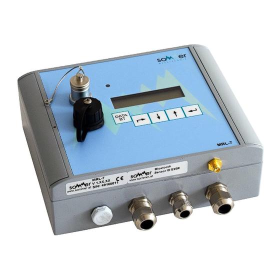
2. Logger functions and interfaces 2.1. MRL-7 key functions and features Fig. 1: MRL-7 key functions and features www.sommer.at page 2... -
Page 9: Measurement And Data Storage Concept
Logger can be operated fully independently (with batteries or solar-module), integrated solar charge controller; no equipment cabinet required due to IP 67 rating Ideal integration and compatibility with complete SOMMER sensor family as well as common sensor technology products ... -
Page 10: Sdi-12 Measurement Example
The diagram below shows the first and second measurement intervals. Fig. 4: SDI-12 measurement At the beginning of every measurement interval the MRL-7 issues a M-command to the first sensor which is answered with information about the number of measurement values available and the time until the data is ready to be requested by the data logger. -
Page 11: Storing Of Measurement Results And Storage Options
D-B) and the values can be reset to “0” once per day (see J-D-A). The sensor types (“S-Typ”) using the conditional storage interval by default are “COUNT” and “SYS” values (see chapter G “Measurements, table” for more information). www.sommer.at page 5... -
Page 12: User Interfaces
2.3. User interfaces 2.3.1. Keyboard and display The MRL-7 display is being activated by pressing any of the buttons. The cursor buttons are used to navigate the on-screen menu. Key Function(s) Exit the current menu / Abort Menu item down / Decrease value... -
Page 13: Parameterisation And Data Transfer
Menu items marked with “ ** ” relate to the logger modem. 2.3.3. Parameterisation and data transfer Several interfaces are available to download stored data and/or to change MRL-7 parameter settings: Table 3: Interface types and features Interface type... -
Page 14: Digital Interfaces
2.4.1. Digital interfaces SDI-12 SDI-12 sensors can be connected to the MRL-7 via the “SDI12 – D” port. (See chapter 3.5 “Pin description” for the port location.) When data is requested from several SDI-12 sensors the sequence of requests starts with the first sensor as specified in the “Measurements, table”... - Page 15 “always on”. RS-485 Sensors manufactured by SOMMER with an RS-485 interface are connected to the MRL-7 via the port “RS485 A”. (See chapter 3.5 “Pin description” for the port location.) The RS-485 interface is always ready to receive measurement values when activated (see chapter J-G “RS485-2”).
-
Page 16: Hardware
3. Hardware The MRL-7 is available in two different configurations: MRL-7: as per standard configuration and without integrated battery MRL-7B: with a higher housing to accommodate an integrated battery Fig. 7: MRL-7 Fig. 8: MRL-7B www.sommer.at page 10... - Page 17 Drawings of MRL-7 housing: Fig. 9: MRL-7 housing, dimensions (in mm) Fig. 10: MRL-7B housing, dimensions (in mm) www.sommer.at page 11...
-
Page 18: How To Open The Housing
Remove the covering strips on the left and right side of the housing. Fig. 11: MRL-7 covering strips Unscrew the screws using a Philips head no. 2 or a straight head screwdriver. -
Page 19: Mounting The Mrl-7
Open the housing by flipping the lid open. Fig. 13: Opening the housing of the MRL-7 3.2. Mounting the MRL-7 After removing the covering strips the MRL-7 can be mounted on a backplane with four screws: Fig. 14: Holes for Mounting Compatible screws: ... -
Page 20: Modem
The following picture shows the slots respectively the bracket where to find, insert and exchange the micro SIM card, the micro SD card and the button cell of the MRL-7. To insert and / or switch the micro SIM card, the micro SD card or the button cell, open the MRL-7 housing as described in chapter 3.1 “How to open the housing”. -
Page 21: Insert / Exchange Of Micro Sim Card
2. Then flip the cover open. 3. The micro SIM card can now be inserted, removed or exchanged. Note the correct orientation of the card to be inserted (it will only fit one way). www.sommer.at page 15... -
Page 22: Insert / Exchange Of Micro Sd Card
3.4.2. Insert / Exchange of Micro SD Card 1. To insert / exchange the micro SD card gently press on the covering with your finger and shift it a little back. 2. Then flip the cover open. www.sommer.at page 16... -
Page 23: Exchange Of Button Cell
3.4.3. Exchange of button cell The MRL-7 is delivered with a button cell built in. This little battery ensures that the time and date function of the logger is not interrupted during the time when the logger lacks any other power supply. -
Page 24: Pin Description
To insert a new cell simply push it with your fingers into the holding bracket from the other side. 3.5. Pin description Fig. 16: MRL-7 pin description www.sommer.at page 18... - Page 25 Table 6: MRL-7 pin assignment Connector Pin(s) Function Left-hand side connectors: Battery connector (-) [internal and/or external battery] Battery connector (+), max. 14 V [internal and/or external battery] - Solar Supply voltage (-) or solar panel connector (-) Not connected / do not use!
- Page 26 Attention: You must not connect any voltages bigger than 30 volts anywhere to the logger or to any pin. Applying voltages above 30 volts you risk your health, physical damages on the device or even a fire! www.sommer.at page 20...
-
Page 27: Spring Clips
3.6. Spring Clips The MRL-7 is delivered with an assortment of spring clips for connecting sensors and power supply lines. 1. 4-pin spring clip 2. Use a flat head screw driver to compress the internal spring. 3. Push the screw driver in... - Page 28 4. Insert the wire. 5. Insert the wire completely. 6. Pull out the screw driver to release the spring and fix the wire. www.sommer.at page 22...
-
Page 29: Usb
“searching Stick”. The Simply press the button MRL-7 searches for a USB flash drive for six seconds. Plug in a USB flash drive now (or also before) and all data are copied automatically to the USB flash drive since the last readout. - Page 30 If screwing on the cap does not work smoothly, it maybe is not put on nicely so that the threads do not fit well. Unscrew the cap and carefully try again. www.sommer.at page 24...
-
Page 31: Mrl-7 Keyboard Operation
5. MRL-7 keyboard operation Fig. 18: MRL-7 keyboard 5.1. Description of keyboard buttons, navigating the menu The cursor buttons are used to navigate the on-screen menu. The button is used to search for a USB flash drive, to activate/search for a Bluetooth connection or for special functions as described further below. -
Page 32: Activating The Display
5.2. Activating the display The MRL-7 display is activated by pressing any button for at least one second and shows the main screen (= station number, current date and current time). After four seconds without any activity on the logger, the display switches and shows automatically the first measurement value. -
Page 33: Settings
5.6. Settings Some MRL-7 settings can be adjusted via the display menu. To adjust the settings activate the MRL-7 display by pressing any button. two times and select the menu “*** Settings ***”. Confirm your selection by pressing Press and input the access code as described above. - Page 34 “Adjusts” the display contrast. There are four different levels available: base, weak, high and medium. 9 Reboot Device Reboots the MRL-7 without the need to switch the supply voltage. This option is helpful for performing firmware updates, which require the device to be restarted. 10 Modem Testmode A number of automatic tests are performed and related information is displayed: ...
-
Page 35: Parameterisation
6. Parameterisation 6.1. Commander The MRL-7 is parameterized with the software Commander or via the terminal menu (see chapter 9.1). To edit the parameters with the PC software Commander, the “Expert” mode must be active (for more details see Commander manual): Fig. -
Page 36: Rs-232
Use the buttons “Next” and “Back” to adjust the different settings from one step to another or press “Cancel” to abort the communication assistant. Select “Serial connection” when using the communication cable. www.sommer.at page 30... - Page 37 Make sure the MRL-7 is supplied with power (either internal batteries and/or external power supply), and the communication cable is plugged into the data logger on one end and the other end is connected to a USB port of the laptop running “Commander”.
- Page 38 (additional steps to define specific port and/or station information). Assign a name to the connection for later use. An automatic search for connected devices is performed. This step can take up to two minutes. www.sommer.at page 32...
- Page 39 by selecting “Connections (F8)” in the main menu item “Tabs” (for temporary display only) by selecting “Show connections tab” that can be found in the main menu item “Options”, submenu item “Tabs” (for permanent display). www.sommer.at page 33...
-
Page 40: Bluetooth
„waiting for BT no access“ is displayed. Keep holding the button displayed. Now a Bluetooth connection can be established with the MRL-7. The MRL-7 Bluetooth ID is printed on a sticker on the MRL-7 housing. www.sommer.at page 34... - Page 41 The communication assistant dynamically changes between 8 and 9 steps, depending on whether an existing connection can be selected or if a new connection has to be established (additional steps to define specific port and/or station information). www.sommer.at page 35...
- Page 42 This step might take a few seconds. www.sommer.at page 36...
- Page 43 This step might take a few seconds. If no matching station exists, a “Name” for the station can be defined. If a station already exists, it will be recognised and automatically selected. Select “Yes” to proceed. www.sommer.at page 37...
- Page 44 by selecting “Connections (F8)” in the main menu item “Tabs” (for temporary display only) by selecting “Show connections tab” that can be found in the main menu item “Options”, submenu item “Tabs” (for permanent display). www.sommer.at page 38...
-
Page 45: Commander: Establishing A Connection
For further information on how to define connections, please see the Commander manual. 6.3. Commander: Establishing a connection To establish a connection to an MRL-7 either a “Connection” or “Station” (6.4 “Defining a station”) can be selected. When a station is selected one of the assigned connections must be chosen. -
Page 46: Defining A Station
Fig. 23: List of parameters 6.4. Defining a station To download stored data, to comfortably manage several MRL-7 devices and to enable additional functions (e.g. IP call), it is advised to create a “station” in Commander. To create a station select the “Stations (F7)”... - Page 47 The MRL-7 serial number (S/N) is printed on the device housing. Fig. 25: Station no. and SOMMER ID Fig. 26: Station no. and SOMMER ID Select which previously defined “Connections” (Serial, Bluetooth, IP Call, …) to assign to the...
- Page 48 “Archive Type”. When set to “None” all data recorded by the MRL-7 will be saved in one file. The default location of downloaded data files is Fig. 29: Data archive “C:\Users\Public\Docum ents\Sommer\Data\”...
-
Page 49: Establish A Connection To A "Station
After the connection is established successfully it is now possible to download parameters Fig. 31: Connecting to a station from the MRL-7, to read out measurement data or to establish a terminal connection. 6.6. Downloading stored data To download data from an MRL-7 select the “Data (F4)”... -
Page 50: Remote Connection Via Ip Call
Fig. 33: Downloading stored data manually 6.7. Remote connection via IP Call To establish a connection to an MRL-7 via an IP call, the MRL-7 has to be assigned to a station which is set up for IP call connection. -
Page 51: Data Transmission Via Http/Ftp
6.9. Time synchronisation The MRL-7 can synchronise its internal clock with a time-server (NTP-Server). The time synchronisation settings are described in chapters I-F “NTP synchronisation time” through I-I “NTP timezone”. -
Page 52: Description Of The Parameters
The parameters are arranged in a main menu with submenus. The menu items are opened and closed by double-clicking them. A Station ID The station ID is set to the MRL-7 serial number by default but can be adjusted by users. Value range 0 ... 99999999... - Page 53 The storage interval defines at which times the measured values are saved. E Measurements, max. number Up to 99 measurement values can be defined for the MRL-7. Depending on the ordered components, SOMMER preconfigures some measurements. However, the end user can define additional measurements. The configuration steps are described in chapter G –...
- Page 54 - as S: The source value’s decimal place is measurement value. assumed for the MRL-7. Scale User defined factor with which the retrieved measurement value is multiplied. Attention: This option is only available when the “Decimals” are not set to “as S”.
- Page 55 - SYS: A set of internally measured values is available to be retrieved and stored: key A: Counts the times the MRL-7 is manually activated via its keyboard. key S: Counts the times the MRL-7 is manually activated via its keyboard with a special key sequence.
- Page 56 If a message for a specific measurement and its limit value is defined (see chapter H “Measurements, table”), a box for the according message number appears. Here the box of the message, that shall be triggered once the limit value status is reached, must be ticked off. www.sommer.at page 50...
- Page 57 H Messages, table The MRL-7 features a configurable messaging system. Messages are transmitted to the defined recipients whenever the “Limit” as set for a measurement value is exceeded or deceeded (according to the message configuration). Column title Description 1 … 16 Unique number assigned to a message.
- Page 58 %tval% Set limit value that was exceeded/deceeded %rval” Measurement result that triggered the message output Message number as defined per MRL-7 setup (01 … 16) %wnum% %cp% Measurement result of a user defined channel. Example: Channel number “02” triggers an E-Mail message. This message shall...
- Page 59 When set to “-1” no PIN is required for the SIM card. It is not possible to change the SIM card’s PIN with the MRL-7. Such changes have to be performed with a different device (e.g. mobile phone). Attention: If the SIM pin is set incorrectly, the SIM card will be locked after three consecutively failing attempts to transfer data.
- Page 60 I-B-I Custom command 2 Setting Description “blank” (default) Configures special commands to be sent to the modem (AT). This feature should be used by modem experts only. All issued AT commands must be answered with “ok” by the connected modem. www.sommer.at page 54...
- Page 61 00:10:00 (default) I-C-C Data transmission offset The data transmission offset is used to prevent several MRL-7 from sending their data to a server at the same time by setting different transmission offsets for every data logger. When the transmission offset is set to “00:00:00” the data will always be transmitted at “full” minutes (when the transmission interval is also set to “full”...
- Page 62 “1” (default) Camera channel – it defines the HTTP camera channel for the images of a camera attached to the logger, which are sent to the SOMMER MDS server (measured data server). The “cham chan” number has to match the image channel in the SOMMER MDS.
- Page 63 Description The MRL-7 is not set to accept remote connections time window The MRL-7 is set to accept CSD calls (if 2G) in the set time frame (see chapter I-K and chapter I-L). time wi. + IP call The MRL-7 is set to accept CSD calls (if 2G) in the set time frame and (default) checks periodically for IP call requests.
- Page 64 MRL-7 shall check if there are any IP call requests to the logger. Unit hh:mm:ss hh:mm:ss 00:01:00 … 00:05:00 Value range 00:01:00 (default) I-P E-Mail/SMTP Settings of the MRL-7 to send out e-mails to be configured by the user according to its individual e-mail server details. www.sommer.at page 58...
- Page 65 I-P-A E-Mail/SMTP Setting Description “blank” (default) Name / address of the e-mail server used by the MRL-7 to send out e- mails (e.g. mail.samplename.at). I-P-B sender Setting Description “blank” (default) E-mail address of the MRL-7 as the sender (e.g. sample@sample.at)
- Page 66 SOMMER suggests not to change the SOMMER ID except if a damaged MRL-7 device is replaced by a new MRL-7. In such a case it can be reasonable to change the SOMMER ID of the replacement device to the SOMMER ID of the original logger in order to guarantee a trouble-free archiving.
- Page 67 “on” (default) BOM is outputted. “off” BOM is not outputted. J-C-E Exposure lock With this setting the option to display measured values on the MRL-7 device display can be switched on and off. Setting Description “off” (default) Measured values are displayed.
- Page 68 5 (default) J-D-F max. Hold On message By using this option, the MRL-7 can be configured to send multiple messages in a user defined interval as long as a measurement value’s trigger condition is fulfilled still. Example: “max. Hold On message” setting = 120 a further message is sent after 120 minutes from the beginning of the trigger condition.
- Page 69 By default, the measurement results are outputted via the RS-232 interface and are available to be retrieved via SDI-12 commands after a measurement was completed. However, it is possible to configure the MRL-7 to output the results only when a command is issued or when a measurement result is saved.
- Page 70 MRL-7. J-E-E MO wake-up sequences In case a connected device records the MRL-7 output strings it might be required for this device to receive a sync, prefix or both before the measured values can be recorded. Setting Description No wake-up sequence is used.
- Page 71 Trig, polling Trig, timeout Trig, sleep while timeout Network scan extension Transparency to RS485-2 Attention: The settings of the MRL-7 must correspond with the settings of the connected sensor(s) to guarantee smooth operation. J-G-A Baudrate Unit 1200 … 115200 Value range...
- Page 72 70 (default) J-G-J Trig, sleep while timeout To save on power consumption the MRL-7 can switch off the RS-485 interface until a measurement result is available. If set to “on” the connected sensor (e.g. RQ-30) must send a “Sync” command to reactivate the RS-485 interface so that it can record the output string sent by the sensor.
- Page 73 Setting Description on (default) Detecting SOMMER devices connected via RS485-2 is activated. J-G-L Transparency to RS485-2 This menu item is available only via the terminal menu (see 9.1 Changing parameters via a terminal). When this menu item is selected commands and responses can be sent and received directly via the RS485-2 interface of the MRL-7.
- Page 74 “off” (default) “2.5V” 2.5V are outputted via the “2.5V Ref Out” pin (see 3.5 Pin description) “0.5mA” 0.5mA are outputted via the “CurrH” pin (see 3.5 Pin description) “2.5V + 0.5mA” Both aforementioned reference values are outputted www.sommer.at page 68...
- Page 75 J-I-D Switch usage With this setting connecting the sensor supply voltage of the MRL-7 through via the switches (SW1, SW 2 and SW3) can be de/activated (see also chapter 3.5). Setting Description “off” (default) The sensor supply voltage is not connected through via the “Switch Out”...
- Page 76 Night recognition View J-J-A switch Setting Description “off” (default) To be set, if the camera does not need a power supply by the MRL-7. “1” Camera is connected to switching output 1. “2” Camera is connected to switching output 2. www.sommer.at...
- Page 77 The warm up time can only be set if the camera is supplied to a switching output. J-J-C Night recognition To safe battery, the MRL-7 can control the camera to prevent it from taking pictures in the darkness (e.g. during the night).
- Page 78 The continuous measurement mode is disabled automatically after 3 minutes. K-D Inspection, nominal values List of internal MRL-7 nominal values that are used for an automatic testing during the production process of the logger. K-E Inspection, start process Starts an automatic testing of the internally generated voltages and of the analogue inputs.
- Page 79 (e.g. this manual) is available at a measurement site. K-H Relaunch program With this menu item the MRL-7 firmware can be restarted. The boot process is the same as if the device’s supply was removed and reconnected. K-I Replace program With this menu item the MRL-7 firmware can be restarted.
-
Page 80: Technical Specifications
Storage temperature: -40°C to +60°C Storage Humidity: 10 to 90 % rH Housing Material: Anodized aluminium Dimensions (W x H x D): MRL-7: 180 x 150 x 60 mm MRL-7B: 180 x 150 x 90 mm Installation: four mounting holes Protection type IP 67 * …... -
Page 81: Appendix
(e.g. “1”). When the above configuration example is identified, the parameter changed last will be set as defined by the user and the conflicting parameter is automatically set to “off”. www.sommer.at page 75... - Page 82 Deleting the „old“ archived data (or shifting it to a new file storage location) locally on the used computer and also erasing all data stored on the MRL-7 to reset the device to a “new” station. PLEASE NOTE: An old archive pointer has been replaced! www.sommer.at...
-
Page 83: Index Of Tables
This message is outputted only when more than 16 different computers were used to archive data collected with the currently connected MRL-7. In almost all cases this message can be ignored. To keep the archive system “clean” SOMMER suggests appointing someone who is mainly responsible for the station(s). - Page 84 Fig. 12: MRL-7 screws ......................12 Fig. 13: Opening the housing of the MRL-7 ................13 Fig. 14: Holes for Mounting ...................... 13 Fig. 15: Lid of the MRL-7 from inside ..................14 Fig. 16: MRL-7 pin description ....................18 Fig.
Need help?
Do you have a question about the MRL-7 and is the answer not in the manual?
Questions and answers