Roland Camm-1 CX-24/12 User Manual
Hide thumbs
Also See for Camm-1 CX-24/12:
- User manual (33 pages) ,
- Manual (20 pages) ,
- Manual (12 pages)
Table of Contents
Advertisement
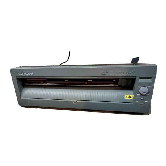
CX-24/12
USER'S MANUAL
Thank you very much for purchasing the CX-24/12.
•
To ensure correct and safe usage with a full under-
standing of this product's performance, please be sure
to read through this manual completely and store it in
a safe location.
•
Unauthorized copying or transferral, in whole or in
part, of this manual is prohibited.
•
The contents of this operation manual and the
specifications of this product are subject to change
without notice.
•
The operation manual and the product have been
prepared and tested as much as possible. If you find
any misprint or error, please inform us.
•
Roland DG Corp. assumes no responsibility for any
direct or indirect loss or damage which may occur
through use of this product, regardless of any failure
to perform on the part of this product.
Advertisement
Table of Contents

Related Manuals for Roland Camm-1 CX-24/12


Summary of Contents for Roland Camm-1 CX-24/12
- Page 1 If you find any misprint or error, please inform us. • Roland DG Corp. assumes no responsibility for any direct or indirect loss or damage which may occur through use of this product, regardless of any failure...
-
Page 2: Table Of Contents
Macintosh is registered trademark or trademark of Apple Computer, Inc. in the USA and other countries. IBM is a registered trademark of International Business Machines Corporation. Adobe and Acrobat are trademarks of Adobe Systems Incorporated. Copyright © 2000 Roland DG Corporation http://www.rolanddg.com/... -
Page 3: To Ensure Safe Use
Ground the unit with the ground the power cord from the electrical outlet, wire. and contact your authorized Roland dealer Failure to do so may result in risk of or service center. electrical shock in the even of a mechanical... - Page 4 Do not use with a damaged power Do not injure or modify the electrical cord or plug, or with a loose power cord, nor subject it to electrical outlet. excessive bends, twists, pulls, Use with any other binding, or pinching, nor place any power supply may object of weight on it.
-
Page 5: About The Labels Affixed To The Unit
About the Labels Affixed to the Unit These labels are affixed to the body of this product. The following figure describes the location and content of these messages. Do not place hands near the platen while in operation. Model name Rating label Use a rated power supply. -
Page 6: Pour Utiliser En Toute Sécurité
électrique de la prise et prise de terre. communiquer avec le revendeur autorisé Le non-respect de cette consigne pourrait Roland ou le centre de service. entraîner des décharges électriques en cas de problème mécanique. Ne pas utiliser avec une alimentation électrique non conforme à... - Page 7 Ne pas utiliser avec une fiche ou un Ne pas endommager ou modifier le fil électrique. Ne pas le plier, le fil électrique endommagé ou avec tordre, l'étirer, l'attacher ou le serrer une prise mal fixée. Une négligence à de façon excessive. Ne pas mettre ce niveau pourrait d'objet ou de poids dessus.
-
Page 8: À Propos Des Étiquettes Collées Sur L'appareil
À propos des étiquettes collées sur l'appareil Ces étiquettes sont collées à l'extérieur de l'appareil. Les dessins suivants indiquent l'endroit et le contenu des messages. Avant N'approchez pas vos mains du plateau de travail quand le chariot est en mouvement. Arrière Nom du modèle Étiquette des caractéristiques... -
Page 9: Checking Supplied Items
This product includes the items shown below. Before starting use, make sure all the items are present. Roller base: 1 Blade: 1 Power cord: 1 Roland Software Package CD-ROM: 1 * CX-24 only Blade holder Startup manual: 1 To Ensure Safe Use: 1... -
Page 10: Part Names And Functions
2 Part Names and Functions 2 Part Names and Functions In explanations that are common for both the CX-24 and the CX-12, figures depicting the CX-24 are used. 2-1 Front View Blade protector Cutting carriage Pinch roller (Left) This presses down on the ma- The blade holder (or terial to hold it in place. -
Page 11: Operation Panel
Part Names and Functions 2-3 Operation Panel Display [MENU/PARAM] Key This displays the various menus and setting This selects whether turning the dial values, as well as error messages. chooses menu items or changes setting values. Pressing this key changes the location of the menu cursor. -
Page 12: Preparing The Cx-24/12
3 Preparing the CX-24/12 3 Preparing the CX-24/12 3-1 Setting Ground the unit with the ground Install on a stable surface. wire. Failure to do so may result in Failure to do so may result in risk of falling of the unit, electrical shock in the even of a mechanical leading to injury. -
Page 13: Connection
3 Preparing the CX-24/12 3-2 Connection NOTICE Connect the cable to either the parallel or the serial port. Be sure that the power to both the computer and the main unit is switched off when connecting the cable. Securely connect the power cord, computer I/O cable and so on so that they will not be unplugged and cause failure during operation. - Page 14 3 Preparing the CX-24/12 Connecting the Power Cord Power outlet Power connector Power cord...
-
Page 15: Installing The Driver
3 Preparing the CX-24/12 3-3 Installing the Driver The included Roland Software Package CD-ROM contains a Windows-based program and driver for performing cutting with the CX-24/ CAMM-1 DRIVER This software is required when sending data from a Windows-based program to the CX-24/12. If you're using Windows, be sure to install this driver. - Page 16 3 Preparing the CX-24/12 Making the Settings from the Menu on the CX-24/12 The display menu can only be used to make settings when material is loaded and set up. Before attempting to make menu settings, refer "4-3 Turning on the Power"...
-
Page 17: Basic Operation
4 Basic Operation 4 Basic Operation 4-1 Installing Blade Do not touch the tip of the blade with your fingers. Doing so may result in injury. NOTICE Be sure to support the tool mounting screw from below when installing the blade holder. Cutting quality may become poor if installed without supporting the screw in this way. -
Page 18: Loading The Material
4 Basic Operation While supporting the screw from below, insert into the blade holder from above. Insert until the collar of the blade holder touches the rim of the hole. Tighten the screw securely. Tug the blade holder upward to make sure it does not come loose. - Page 19 4 Basic Operation Loading the Material Before you load material, make sure the sheet loading lever is lowered. - If you are using roll material, start with step 1. - If you are using piece material, start with step 2. Pass the end of the material between the pinch rollers and the grit rollers so that it extends from the front of the unit.
- Page 20 4 Basic Operation CX-12 Position the material so that the left and right edges are each above one of the grit rollers. The white areas of the rails serve as a guide for positioning the grit rollers. Align so that the left and right edges of the material are parallel with the guide lines.
-
Page 21: Turning On The Power
4 Basic Operation 4-3 Turning on the Power Do not place the hands or anything else on the platen when switching on the power. Doing so may result in injury. (The cutting carriage moves simultaneously when the power is switched on.) Turn on the CX-24/12. - Page 22 4 Basic Operation The width of the material is detected and the unit is made ready for cutting. When flat material is loaded, the material moves to the front and rear to detect the length of the material as well. At this time, if the material is crooked and looks like it might come loose from the pinch rollers, or actually does come loose, reload the material.
-
Page 23: Checking Material Feed
4 Basic Operation 4-4 Checking Material Feed Make sure that the material does not come loose from the pinch rollers while cutting is in progress. On the CX-24, when you choose [PIECE] as the material type, the material is moved forward and backward in order to detect the length of the material. -
Page 24: When Performing Long Cutting
4 Basic Operation 4-5 When Performing Long Cutting Cutting a length of 1.5 m (59 in.) or more requires material that is at least 50 mm (2 in.) wider than the necessary cutting width. Prepare material that is at least 50 mm (2 in.) wider than the necessary cutting width. -
Page 25: Setting The Origin Point
4 Basic Operation 4-6 Setting the Origin Point Loading material and pressing the [ENTER] key automatically sets the origin point for cutting. The origin point set when you do this varies according to model and the shape of the selected material. Model Material shape selected from the menu Location of the origin point... -
Page 26: Performing A Cutting Test (How To Adjust Blade Force/Adjusting The Cutter Blade)
4 Basic Operation 4-7 Performing a Cutting Test (How to Adjust Blade Force/Adjusting the Cutter Blade) Before carrying out actual cutting, you may wish to perform a "cutting test" to check whether the unit produces the cutout satisfactorily. This is done by examining the results of the cutting test, and adjusting the blade force and the amount of blade extension. The cutting test should be repeated until the appropriate cutting conditions for the material in use are discovered. -
Page 27: Adjusting The Amount Of Blade Extension
4 Basic Operation Turn the dial to display the screen shown at right. FORCE | < 80g> Press the [MENU/PARAM] key. The menu for setting the blade force appears. Turn the dial clockwise to increase the blade force in FORCE | <... -
Page 28: Downloading Cutting Data
Using the CX-24/12 to cut data created using a program requires the CAMM-1 driver. The CAMM-1 driver is in the included Roland Software Package. For information on how to install it, take a look at the included Startup Manual. - Page 29 4 Basic Operation Click the [Size] tab and make the settings for the cutting range at the screen shown at right. Click the [Tools] tab. Clicking the drop-down arrow displays the numerals [1] through [8] and the [Machine Settings] selections. To specify the speed for performing cutting using the driver, choose a number from [1] to [8] and enter the cutting conditions.
- Page 30 Halt transmission of cutting instructions from the computer. Click [Start]. Click [Settings], then click [Printers]. Double-click the printer icon. For the CX-24: [Roland CAMM-1 CX-24] For the CX-12: [Roland CAMM-1 CX-12]. At the [Printers] menu, click [Purge Print Jobs]. Make sure the displayed data for the file being printed disappears.
-
Page 31: Applying The Completed Cutout
4 Basic Operation 4-9 Applying the Completed Cutout When cutting ends, affix the material you created. Before you affix the material, cleaning the location where you want to affix it to remove any dust or grease. When applying on a transparent medium such as window glass, it may be helpful to draw guide lines on the back of the glass with a water-based pen (so that the lines can be wiped off after applying the material). - Page 32 4 Basic Operation - For Roll Materials, or When Detaching Only a Cut Portion commercially available knife to sever the material along the knife guide. Knife Guide Use tweezers to peel off unneeded portions of the material you created. You should have weed boarders or rectangles drawn around work to facilitate weeding.
-
Page 33: When Cutting Is Completed
4 Basic Operation 4-10 When Cutting is Completed When not in use for extended periods, unplug the power cord from the electrical outlet. Failure to do so may result in danger of shock, electrocution, or fire due to deterioration of the electrical insulation. -
Page 34: Performing A Self-Test
5 Performing a Self-test 5 Performing a Self-test The CX-24/12 is equipped with a "self-test" function to conveniently allow you to check whether or not it is capable of operating normally. If the CX-24/12 is not performing correctly, follow the steps below to perform a self-test. A computer is not required in order to carry out the self-test. -
Page 35: Plotting On Paper Media
6 Plotting on Paper Media 6 Plotting on Paper Media Before cutting, plotting using pen and paper can ensure that your design is correct without wasting materials. This feature can also be used to plot template designs on thick materials that may not be able to cut. Since the design of the CX-24/12 differs inherently from that of dedicated plotters, it does not accommodate functions such as high-speed plotting, automatic pen changes, pen dry protection, or the like. -
Page 36: Repeating The Same Cutting
7 Repeating the Same Cutting 7 Repeating the Same Cutting The CX-24/12 can store the data sent from the computer in a buffer (a temporary memory area), and use this data to repeat cutting. In the setup state, when cutting data is sent, the data is buffered at the same time that cutting starts. Data sent until the setup state is released can be recut. - Page 37 7 Repeating the Same Cutting Getting Ready for Recutting Repeating cutting without replacing the material Use the position keys to move the blade holder to the location for setting a new origin point. Press the [ORIGIN] key to set the origin point. Repeating cutting on different material Turn the dial to display the screen shown at right.
-
Page 38: About The Blades And Materials
8 About the Blades and Materials 8 About the Blades and Materials 8-1 Blade and Material Combinations The table below provides information on combinations of materials and blades, cutting conditions, and useful life. The figures for blade life are only estimates. The conditions described below may not apply all cases. Before you perform cutting, be sure to carry out a cutting test to check and adjust the quality. -
Page 39: About The Materials
8 About the Blades and Materials 8-2 About the Materials Loadable Material Width The location of the grit rollers (where the material is held in place by the pinch rollers) differs according to the model. Referring to the figure below, place the material on the grit rollers and check where it can be held in place by the pinch rollers. CX-24 : Grit roller : Pinch roller (left) - Page 40 8 About the Blades and Materials About the Cutting Area The cutting area along the horizontal plane (the direction in which the tool carriage moves) is determined by the position of the pinch rollers. The workable area spans the length between the two rollers, minus a margin of about 1 mm (about 0.04 in.) on both sides. If you selected [PIECE] on the CX-24, then when the length of the material is 1,600 mm (63 in.) or more, the CX-24 determines it to be roll material, and sets the length at 24,998 mm (984-1/8 in.).
- Page 41 8 About the Blades and Materials A material with edge holes for sprocket feed Material for sprocket-feed use has feed holes along both edges. If the material is loaded with these holes lying over the pinch rollers, material feed cannot be performed correctly. Do not put the pinch rollers on the hole area at the edges.
-
Page 42: Display Menu Descriptions
9 Display Menu Descriptions 9 Display Menu Descriptions 9-1 How to Read This Chapter The explanations in this chapter use the following format. This is the information that appears on the display. Stored in Memory FORCE | < 50g> When set to "Yes," the setting values are stored This indicates the factory 50 g... - Page 43 9 Display Menu Descriptions Stored in Memory FORCE < 50g> 50 g Factry Default 30 to 200 g Setting Range 10 g Steps This sets the blade force used when cutting material. Description Perform a cutting test and set the conditions to match the loaded material and the installed cutter.
- Page 44 9 Display Menu Descriptions Stored in Memory REPLOT | START START, CLEAR Selection Choices START Description This performs cutting using the data in the replot buffer when the [ENTER] key is pressed. CLEAR This deletes the data in the replot buffer when the [ENTER] key is pressed. Stored in Memory ROTATE| <OFF>...
- Page 45 9 Display Menu Descriptions Stored in Memory WEIGHT| <LIGHT> LIGHT Factry Default LIGHT, HEAVY Selection Choices Sets the weight of the material. If material feed is not performed smoothly, Description set this switch to [HEAVY]. When set to [HEAVY], the upper limit for the cutting speed is set at 10 cm/ sec., and the force used to move the material and the blade increases.
- Page 46 9 Display Menu Descriptions Stored in Memory #BAUD.| <9600> 9600 Factry Default 9600, 4800 Selection Choices This sets the communication speed for a serial connection. Description It is displayed only when connected to the computer using a serial cable. Stored in Memory #DATA.| <8>...
- Page 47 9 Display Menu Descriptions Stored in Memory LANG. |< ENGLIS> ENGLISH Factry Default ENGLIS, , Deut., FRANÇ, , ITAL.,PORTUG, Selection Choices This selects the language for messages on the display. To display this menu, Description switch on the power while holding down the [MENU/PARAM] key. Stored in Memory UNIT | <Metric>...
-
Page 48: Display Menu Flowchart
- Making Menu Settings with the Control Panel." Turned clockwise Turned counterclockwise [MENU/PARAM] +POWER ON [ ] +POWER ON LANG. |<ENGLIS> DEMO CUT Roland DG Corp. , Englis, Deut. ITAL., PORTUG [ENTER] +POWER ON SELCT | ROLL SETUP -> ENTER UNIT |<Metric>... -
Page 49: What To Do If
11 What to do if... 11 What to Do If... 11-1 If the CX-24/12 Doesn't Run... Is the CX-24/12 power on? Turn on the power. Is the CX-24/12 in the setup state? When the display shows the following message, cutting cannot be performed even when data is sent. When you enable the setup state, cutting starts. -
Page 50: The Material Slips Away From The Pinch Rollers During The Cutting Process
Are the pinch rollers damaged or deformed? If the material comes loose even when it is loaded correctly, the useful life of the pinch rollers has ended. If this happens, contact your authorized Roland DG Corp. dealer or service center. (Replacement is a charged service operation.) -
Page 51: Uncut Areas Remain, Or Areas Are Not Cleanly Cut
If material is not cut properly even though the CX-24/12 settings are correct and the blade and cutter holder are installed correctly, the blade protector may be damaged. If this happens, contact your authorized Roland DG Corp. dealer or service center. (Replacement is a charged service operation.) -
Page 52: Error Messages
11 What to do if... 11-5 Error Messages The location of one or more of the pinch rollers is not correct. Err:Bad Positin Press the [ENTER] key to clear the error. Position the pinch rollers appropriately over the grit rollers and reload the material. -
Page 53: Instruction Support Chart
A "CAMM-GL III Programmer's Manual" is available for separate purchase for those wishing to create their own programs for this machine. For further information, please contact your authorized Roland dealer or service center. The list uses marks, each of which means:... -
Page 54: Specifications
35 to 80% (non-condensing) Accessories Power Cord x 1, Blade x 1, Blade Holder XD-CH3 (Cutter holder and pin) x 1, Startup Manual x 1, To Ensure Safe Use x1, Roland Software Package CD-ROM x 1, Roller base x 1* *..CX-24 only... - Page 55 13 Specifications Parallel Standard In compliance with the specifications of Centronics Input signals STROBE (1 BIT), DATA (8 BITS) Output signals BUSY (1 BIT), ACK (1 BIT) Level of input/output signals TTL level Transmission method Asynchronous Serial Standard RS-232C specifications Transmission method Asynchronous, duplex data transmission Transmission speed...
-
Page 56: Index
Index Index HEAVY ................45, 51 How to view the display ............22 Acceptable material widths ........... 39 Affix the material ..............31 Amount of blade extension ..........27, 51 I/O ..................45 AREA ..................43 Installing ................15 AUTO ..................45 Installing blade .............. - Page 57 Index RESTORE ................45 ROLL ............... 21, 25, 42 Roll material ..............18, 19 Roller base ................19 ROTATE ................44 Rubber sandblast stencils ............41 SELECT ................42 Self-test .................. 34 SERIAL ................. 45 Serial cable ................13 Serial input connector ............10 Setting ..................
- Page 58 R2-OOO612...
Need help?
Do you have a question about the Camm-1 CX-24/12 and is the answer not in the manual?
Questions and answers