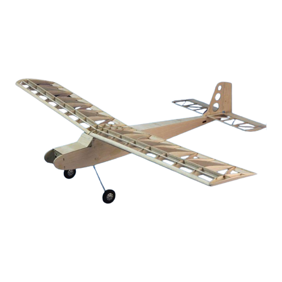
Summary of Contents for HOBBY EXPRESS Micro-Telemaster Kit
- Page 1 MICRO TELEMASTER Hobby Lobby International 5614 Franklin Pike Circle Brentwood TN 37027 USA Phone 866-512-1444 MADE IN THE USA...
- Page 2 Terminology used in this manual. With the precision of laser cut parts and notch and tab construction, the assembly and gluing sequence becomes very important. If components are glued in place to soon, they will not allow enough move- ment to install other components. When instructed to install a part, do only that. You will be instructed to glue it when it is no longer required to be moveable.
-
Page 3: Fuselage Assembly
Fuselage Assembly c 1 Glue the fuselage doubler (FD) to fuselage side (FS). Use the 1/8” dowel in the holes at the top to align the two parts but do not allow the dowel to get glue on it. Make a LEFT and a RIGHT fuselage side assembly. - Page 4 c 4 Glue F2 in the same manner. ABOVE: The right fuselage side has F1, F2, F3 and the servo tray installed and is ready for the left side to be installed. c 5 The servo tray (ST) requires some prefabrica- tion before installing it into the fuselage.
- Page 5 c 11 Carefully align the fuselage bottom sheet- ing (FB) with the forward fuselage assembly and glue it from the F1 back to F2. Pull the tail section together and glue it. Work your way from aft of the landing gear to the tail with glue making sure the sides conform to the shape of the bottom sheeting.
-
Page 6: Stabilizer Assembly
This concludes the basic assembly of the fuselage. The wing mounting bracket will be install into the fuselage later after the wing has been assembled and the wing attachment magnets have been installed into the wing. STABILIZER ASSEMBLY Place the stabilizer plans on the work bench and cover them with wax paper. -
Page 7: Wing Assembly
WING ASSEMBLY c 1 Place the wing plans on the building bench and cover them with waxed paper to protect them from glue. c 2 Locate W1 and W1-B (the little donuts on the 1/8” sheet) and glue a W1-B to the 1/8” holes in W1. - Page 8 c 6 Install and glue the root rib (W1) and the tip rib (W3) to WTEP and SP-B. Use a straight edge at W1 to assure it is straight, as it will in- terface with the opposite wing panel on final assembly.
-
Page 9: Joining The Wing Panels
c 14 Plane and sand the leading edge to contour with the ribs using the included leading edge template as a guide. c 15 Glue in two 1/16” x 3/16” magnets in the holes provided in the trailing edge. c 16 Sand the trailing edge to contour with the ribs. - Page 10 FINAL ASSEMBLY AND COVERING c 1 Place the wing assembly upside down on the bench and place the rear wing mount (RWM) over the magnets. Place one of the 1/8” x 1/4” magnets in each of the holes provided. Make sure the magnets attract.
-
Page 11: Wheel Assembly
WHEEL ASSEMBLY c 1 Install a 3/32” x 3/8” brass tube into one of the wheel covers (WC). Place a wheel hub (WH) down over the brass tube and glue it to the wheel cover. Use a contact adhesive such as 3-M 77 spray glue to spray one side of all four foam tires. - Page 12 PART LOCATOR Part # Qty. Sheet # Size Material Usage 1/8” X 3” X 18” BALSA Elevator 1/32” X 2-1/2” X 5-1/2” AC PLY Elevator horn 1/16” X 4” X 36” BALSA Fuselage former #1 1/16” X 4” X 36” BALSA Fuselage former #2 1/16”...
- Page 13 Hobby Lobby International 5614 Franklin Pike Circle Brentwood TN 37027 USA Phone 866-512-1444...


Need help?
Do you have a question about the Micro-Telemaster Kit and is the answer not in the manual?
Questions and answers