Table of Contents
Advertisement
Advertisement
Table of Contents

Summary of Contents for Bishamon Lift2K
- Page 1 H Y D R A U L I C L I F T T A B L E S ® Models Lift2K , Lift3K™, Lift5K™...
- Page 2 Please note: This manual was current at the time of printing. To obtain the latest, most updated version, please contact Bishamon’s customer Service Department or go to our website: www.Bishamon.com BISHAMON INDUSTRIES CORPORATION 5651 East Francis Street Ontario, California 91761, USA...
-
Page 3: Table Of Contents
12 - Reservoir Fluid Level ..................................10 Figure 13 - Hydraulic Schematic - Plumbing Diagram ............................11 Figure 14 - Lift2K 115 Volt Wiring Diagram ................................ 12 Figure 15 - Lift3K , Lift5K 115 Volt Wiring Diagram ............................12 Figure 16 - Lift3K, Lift5K 208/230 Volt 3 Phase Wiring Diagram ........................ -
Page 4: Getting Started
PLEASE READ THIS MANUAL CAREFULLY BEFORE USING THE OPTIMUS™ Scissor Lift Table. The safety of all persons installing, using or servicing the OPTIMUS™ scissor lift is of utmost importance to Bishamon. All OPTIMUS™ series lifts are capable of supporting heavy loads and are capable of causing SEVERE PERSONAL INJURY if used improperly or certain safety precautions are not taken. -
Page 5: Safety Warning Label Locations
ALWAYS ensure all safety warning labels are in place and legible. If not, remove the lift table from service and replace the required labels. Refer to Figure 1 for label descriptions and locations. ALWAYS securely anchor the base frame to the fl oor to ensure maximum stability. CAUTIONS DO NOT continue to operate the pump if a squealing noise is heard coming from the pump. -
Page 6: Responsibilities Of Owners/Users
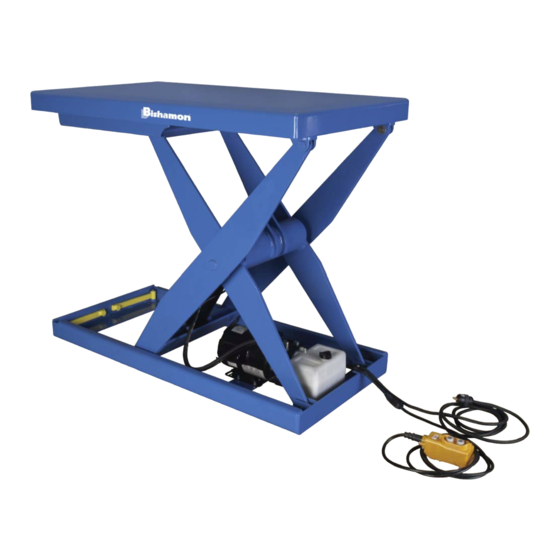
Industrial scissors lift refers to the OPTIMUS series lifts – models Lift2K, Lift3K and Lift5K. • Operating and maintenance manual refers to this manual – “OPTIMUS LK Series Lift2K, Lift3K and Lift5K Series Operation and Service Manual”. Basic Principles - Owners/users shall apply sound principles of safety, training, inspection, maintenance, and expected operating environment. It shall be the responsibility of the owner/user to advise the manufacturer where defl... -
Page 7: Specifi Cations
FIXED PLATFORM MODEL SPECIFICATIONS AND SPECIFICATION DRAWING Figure 2 Fixed Platform Model Specifi cation Drawing... -
Page 8: Figure 3 Turntable Model Specifi Cation Drawing
TURNTABLE MODEL SPECIFICATIONS AND SPECIFICATION DRAWING Figure 3 Turntable Model Specifi cation Drawing... -
Page 9: Recommended Floor Area
RECOMMENDED FLOOR AREA Figure 4 Recommended Floor Area The lift table’s recommended fl oor area, shown in Figure 3, identifi es the “Danger Zone” and the “Operating Zone”. The Danger Zone is the area inside the base frame and under the platform structure. The recommended Operating Zone is a distance of 39 inches (1 meter) extending beyond the danger zone on all sides. -
Page 10: Maintenance Bar Operating Instructions
MAINTENANCE BAR OPERATING INSTRUCTIONS To Engage The Maintenance Bars: Remove all load from the platform and raise the lift table to its fully-raised position. Move to the roller end of the lift. As detailed in Figure 4, rotate each maintenance bar approximately 90° until the bar contacts the roller channel. -
Page 11: Operating Instructions
Position the lift in the desired location. Use care not to damage the lift’s power cord or control cord. The OPTIMUS base frame must be secured to the fl oor for maximum stability. Contact your Dealer or Bishamon Industries Corporation if you have any questions regarding the proper installation of the lift. -
Page 12: Routine Maintenance
Figure 10 Hand Control Operation Figure 11 Foot Control Operation Loading / Unloading the Lift Platform Check the load or component weight to ensure the total load does not exceed the capacity of the lift. Refer to the capacity decal on the end of the lift platform. -
Page 13: Figure 12 Reservoir Fluid Level
Daily Inspection If the OPTIMUS lift is equipped with an accordion bellows skirt, lift the bottom of the bellows skirt and secure it in the raised maintenance position with the maintenance ties. ALWAYS engage the maintenance bars and ensure the scissors mechanism is securely blocked in the raised position before performing ANY lift inspection or maintenance. -
Page 14: Figure 13 Hydraulic Schematic - Plumbing Diagram
Bishamon Industries supplies the OPTIMUS LK series lift tables with Goldenwest Lubricant Premium AW Hydraulic Oil 32, a quality hydraulic oil with rust and oxidation inhibitors and anti-wear properties for use in normal ambient temperatures. -
Page 15: Figure 14 Lift2K 115 Volt Wiring Diagram
Figure 14 Lift2K 115 Volt Wiring Diagram Figure 15 Lift3K, Lift5K 115 Volt Wiring Diagram... -
Page 16: Figure 16 Lift3K, Lift5K 208/230 Volt 3 Phase Wiring Diagram
Figure 16 Lift3K, Lift5K 208/230 Volt 3 Phase Wiring Diagram Figure 17 Lift3K, Lift5K 480 Volt 3 Phase Wiring Diagram... -
Page 17: Figure 18 Lift3K, Lift5K 230 Volt Single Phase Wiring Diagram
Figure 18 Lift3K, Lift5K 230 Volt Single Phase Wiring Diagram Figure 19 Hand Control Wiring Diagram... -
Page 18: Figure 20 Foot Control Wiring Diagram - 20A
Figure 20 Foot Control Wiring Diagram - 20A Figure 21 Foot Control Wiring Diagram - 15A... -
Page 19: Troubleshooting
REPLACEMENT PARTS Bishamon has carefully selected the components used in the manufacture of the OPTIMUS lift tables. In the event replacement parts are required, ALWAYS use genuine OPTIMUS components provided by Bishamon. These parts can be obtained from your Bishamon DEALER or by contacting...


Need help?
Do you have a question about the Lift2K and is the answer not in the manual?
Questions and answers