Table of Contents
Advertisement
PAUL-GOTHE-GmbH Bochum
Wittener Straße 82
D-44789 Bochum
for
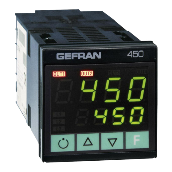
Temperature controller (36.022 and 36.022-DUO)
Before use check the electrical condition of the appliance. For your safety: Don't connect with the power
supply if you can see any damage.
The temperature controller can be used in conjunction with the permissible temperature sensors
according to specification for controlling of heating elements / cartridges.
More information and the Declaration of Conformity can be found at service and support on:
www.paulgothe.com
How to use:
1
Connect the temperature couple to the NiCr-Ni port.
2
Connect the power supply from the heating cartridges / heating elements at the electric socket.
3
Connect the power supply from the controller and meet all necessary protective measures according
to local regulations. Use the power switch at the rear to turn the unit on.
4
Set the desired temperature with the arrows.
5
Heating modes are indicated by left LED (left LED indicates heating, right LED permanent light).
6
Device is provided with a breakage protection element. Should the temperature couple fail, no
output voltage is enabled.
7.
If temperature more as 400 °C the alarm function will be activated and heating stopped (right LED
goes out.
Technical Data
Housing:
Operating conditions:
Supply voltage:
Operating range:
Output voltage:
Protection:
If at the power exit is no 220V ("not heating"):
Please disconnect controller from power and open the cover:
1. Please check the fuse at the main switch and the fuse inside the unit (DUO: fuses) and replace them
if necessary (5 A slow-blow, only the DUO-Version: fuse at the main switch: 10 A).
2. If fuse is OK, please replace relay (replacement relay is glued). Instructions for replacing the relay
can be found on our website under Service and Support.
If the controller continuously supplies 220V ("don't regulate but constant power"):
1. Exchange the relay (replacement relay is glued). Instructions for replacing the relay can be found
on our website under Service and Support.
More information and the Declaration of Conformity can be found at service and support on:
Manual
Material: Makrolon ® (thermoplast. polycarbonate plastic)
-10 ... +50°C
max. 230 V, 48 ... 62 Hz
depending on the temperature sensor NiCr-Ni: 20 ... 390 °C
2 x max. 250 V, max. 5 A, circuit via contactor for heating
IP 35
www.paulgothe.de
10/17
Advertisement
Table of Contents

Related Manuals for gefran 450-R-R-1


Summary of Contents for gefran 450-R-R-1
- Page 1 PAUL-GOTHE-GmbH Bochum Wittener Straße 82 D-44789 Bochum Manual Temperature controller (36.022 and 36.022-DUO) Before use check the electrical condition of the appliance. For your safety: Don’t connect with the power supply if you can see any damage. The temperature controller can be used in conjunction with the permissible temperature sensors according to specification for controlling of heating elements / cartridges.
- Page 2 PAUL-GOTHE-GmbH Bochum Wittener Straße 82 D-44789 Bochum Short Operating Instruction for temperature regulator 450 We deliver our temperature regulator in its basic adjustment for the control of heaters. For other applications, the parameters should be accordingly modified with the help of the attached operating instruction. Link: There is a link for the thermocouple (NiCr Ni, type K) on the front plate.
-
Page 3: Table Of Contents
CONFIGURABLE CONTROLLER INSTALLATION AND OPERATION MANUAL Software Version 1.0x Code 81505C / Edition 04 - 10-2016 - ENG GENERAL INDEX page Standard configuration menu Graphic symbols used Preliminary instructions General description Configuration and programming Electrical interface Alarms Preliminary warnings Installation and connection Control actions Electrical power supply Manual Tuning... -
Page 4: Graphic Symbols Used
Indicates the contents of the various manual sections, Indicates a suggestion based on the the general warnings, notes, and other points to experience of the GEFRAN Technical Staff, which the reader’s attention should be drawn. which could prove especially useful under... -
Page 5: Preliminary Warnings
In the same Download section of the Gefran Web Site These details must always be kept close at hand and www.gefran.com the instrument serie 450 reference... -
Page 6: Installation And Connection
2 • INSTALLATION AND CONNECTION This section contains the instructions necessary damage to persons, machinery or materials, it is for correct installation of the instrument series essential to connect it up to auxiliary alarm equipment. 450 into the machine control panel or the host It is advisable to make sure that alarm signals are system and for correct connection of the also triggered during normal operation. -
Page 7: Advice For Correct Installation For Emc
Direct Current. connection: - the voltage between neutral and earth must not be >1V GEFRAN S.p.A. declines all responsibility for - the Ohmic resistance must be < 6Ω; any damage to persons or property caused •... -
Page 8: Dimensions And Cut-Out
Dimensions and cut-out Installation with panel mounting Warnings and instructions for mounting to the panel Instructions for installation category II, pollution level 2, double isolation. As well as the actual instrument and these instructions for use, the controller package also contains: The equipment is intended for permanent indoor installations within their own enclosure or panel mounted enclosing the rear housing and exposed... -
Page 9: Electrical Connections
Electrical Connections • Outputs • Inputs • TC Generic user-configurable output Available thermocouples: J, K, R, S, T, B, E, N Out2 (Al) - relay 5A/250Vac - Respect polarities - For extensions, use compensated cable appro- priate for thermocouple. Out1 (Main) - relay 5A to 250Vac - logic 12Vdc (6Vmin to 20mA) •... -
Page 10: Functions
3 • FUNCTIONS his section describes the use and functions of the displays, lighted indicators and buttons making up the controller operator interface. It therefore contains essential information for correct programming and configuration of the controllers. Operator interface PV Display: Indication of process variable Indication of output states Error Indication: LO, HI, Sbr, Err OUT 1 (Main);... -
Page 11: Standard Configuration Menu
4 • STANDARD CONFIGURATION MENU Setting Parameters Configurat. S.tu Autotuning Selftuning Softstart Default Custom continuous Enable selftuning, S. t v autotuning, softstart Proportional heating h. P b 10.0 range or hysteresis in 0 ... 999,9% f.s. regulation ON/OFF h. I t Integral heating time 0,00 ... -
Page 12: Configuration And Programming
5 • PROGRAMMING and CONFIGURATION LEVEL 1 DISPLAY Pressed for approx. Software version P.V. 2 sec and jumper S4 (CPU) ON Process Variable (PV display) S.V. Keep the F key Work setpoint (SV display) or value of control pressed to scroll output with controller in manual Setting parameters the menus... -
Page 13: Alarms
• InP Digital filter 0,0 ... 20,0 sec on main input Input settings Configuraz. CtrL Type of control Default Custom Digital filter on display of 0 ... 9,9 P hot process variable; acts as Type of control scale points P cold hysteresis [0...91] PI hot... -
Page 14: Control Actions
If the Integral Time value is too long (Weak integral action), deviation between the controlled variable and the setpoint may persist. Contact GEFRAN for more information on control actions. 81505C_MHW_450_10-2016_ENG... -
Page 15: Manual Tuning
8 • MANUAL TUNING A) Enter the setpoint at its working value. B) Set the proportional band at 0.1% (with on-off type setting). C) Switch to automatic and observe the behavior of the variable. It will be Process similar to that in the figure: Variable D) The PID parameters are calculated s follows: Proportional band Peak... -
Page 16: Self-Tuning
11 • SELF-TUNING The function works for single output systems (heating or cooling). The self-tuning action calculates optimum control parameter values during process startup. The variable (for example, temperature) must be that assumed at zero power (room temperature). The controller supplies maximum power until an intermediate value between starting value and setpoint is reached, after which it zeros power. -
Page 17: Technical Specifications
13 • TECHNICAL SPECIFICATIONS Display 2x4 digit green LED’s, digit height 10mm and 7mm Keys 4 mechanical keys (Man/Aut, INC, DEC, F) Accuracy 0.2% f.s. ±1 digit at 25°C ambient temperature Main input TC, RTD (Pt100) Thermocouples IEC 584-1 (J, K, R, S, T, B, E, N) Cold junction error 0,1°... -
Page 18: Accessories
ACCESSORIES 14 • • Interface for GEFRAN instrument configuration Kit for PC via the USB port (Windows environment) for GEFRAN instruments configuration: KIT PC USB / RS485 o TTL Lets you read or write all of the parameters • A single software for all models •...
Need help?
Do you have a question about the 450-R-R-1 and is the answer not in the manual?
Questions and answers