Table of Contents
Advertisement
Advertisement
Table of Contents

Related Manuals for Midland Alan 8001 XT


Summary of Contents for Midland Alan 8001 XT
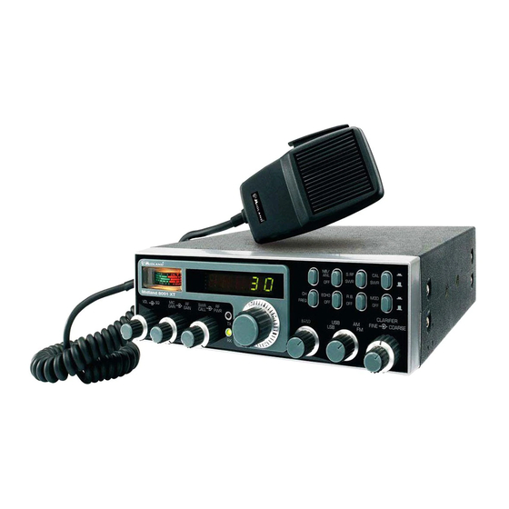
- Page 1 Manual de utilizare in Limba Engleza Statie radio CB Alan 8001 XT...
- Page 2 TABLEwOFwCONTENTSw Installation ........................2 Location ........................2 Mounting the Connection .................... 2 Ignition Noise Interference .................... 2 AntennaE ........................2 TuningEtheEAntennaEforEOptimumESWRE ............... 3 ExternalESpeakerE ......................4 Replacing fuse ......................4 Operation ........................4 ControlsEandEIndicatorsE ....................4 Front Panel ........................4 Real Panel ........................
-
Page 3: Installation
INSTALLATION LOCATION PlanAtheAlocationAofAtheAtransceiverAandAmicrophoneAbracketAbeforeAstartingAtheAinstallation+A SelectAaAlocationAthatAisAconvenientAforAoperationAandAdoesAnotAinterfereAwithAtheAdriverAorA passengersAinsideAtheAvehicle+AInAcars(AtheAtransceiverAisAusuallyAmountedAbelowAtheAdashA panel(AwithAtheAmicrophoneAbracketAbesideAit+A MOUNTING THE CONNECTION TheAtransceiverAisAsuppliedAwithAaAuniversalAmountingAbracket+AWhenAmountingAtheAbracketA andAradioAinsideAyourAcar(AmakeAsureAitAisAmechanicallyAstrong+AAlsoAprovideAaAgoodAelectricalA connectionAtoAtheAchassisAofAtheAvehicle+AToAmountAtheAtransceiver(AproceedAasAfollows:A 4+A AfterA youA haveA determinedA theA mostA convenientA locationA inA yourA vehicle(A holdA theA transceiverA withA mountingA bracketA inA theA exactA locationA youA haveA chosen+A IfA nothingA interferesAwithAmountingAitAinAtheAdesiredAposition(AremoveAtheAmountingAbolts+ABeforeA drillingAtheAholes(AmakeAsureAnothingAwillAinterfereAwithAtheAinstallationAofAtheAmountingA bolts+A q+AConnectAtheAantennaAcableAplugAtoAtheAstandardAreceptacleAonAtheArearApanel+AMostACBA... - Page 4 directionOofOtheObodyOofOtheOvehicleCOForOallOpraticalOpurposes4Ohowever4OtheOradiationOpatternO isO nondirectionalCO TheO slightO directionalO characteristicO willO beO observedO onlyO atO extremeO distancesCOAOstandardOantennaOconnectorOWtypeOSOOk:NBOisOprovidedOonOtheOtransceiverOforO easyOconnectionOtoOaOstandardOPLOk/NOcableOterminationCOIfOtheOtransceiverOisOnotOmountedO onOaOmetalOsurface4OitOisOnecessaryOtoOrunOaOseparateOgroundOwireOfromOtheOunitOtoOaOgoodO metalOelectricalOgroundOinOtheOvehicleCOWhenOinstalledOinOaOboat4OtheOtransceiverOwillOnotO operateOatOmaximumOeff cientlyOwithoutOaOgroundOplate4OunlessOtheOvesselOhasOaOsteelOhullCO BeforeOinstallingOtheOtransceiverOinOaOboat4OconsultOyourOdealerOforOinformationOregardingOanO adequateOgroundingOsystemOandOpreventionOofOelectrolysisObetweenOf ttingsOinOtheOhullOandO waterCO TUNINGrTHErANTENNArFORrOPTIMUMrSWRr SinceOthereOisOsuchOaOwideOvarietyOofObaseOandOmobileOantennas4OthisOsectionOwillOstrictlyO concernOitselfOtoOtheOvariousOtypesOofOmobileOadjustableOantennasCOBecauseOtheOantennaO lengthOisOdirectlyOrelatedOtoOtheOchannelOfrequency4OitOmustObeOtunedOtoOresonateOoptimallyO allO-DOchannelsOofOtheOtransceiverCOChannelOROrequiresOaOlongerOantennaOthanOChannelO-DO becauseO itO isO lowerO inO frequencyCO DueO toO theO variousO methodsO ofO adjustingO antennasO forO properOSWROweOhaveOchosenOwhatOweOthinkOisOtheOoptimumOmethodGO A.rAntennasrwithradjustmentrscrewsrgsetrscrews).r RCOStartOwithOtheOantennaOextendedOandOtightenOtheOsetOscrewOlightlyOenoughOsoOthatOtheO...
- Page 5 436 RF6GAIN6CONTROL60outer6dual6concentricB3 It-reduces-the-gain-of-the-RF-amplif er- under-strong-signal-conditionsk- 536 SWR6CAL6CONTROL60inner6dual6concentricB3 In-order-to-achieve-maximum-radiated- power-and-the-longest-rangeL-it-is-important-that-your-antenna-is-in-good-conditionsL- properly-adjusted-and-matched-to-your-transceiverk-The-builtPin-SWR-6standing-wave- ratio4- meter- lets- you- easily- measure- your- operating- antenna- conditionsk- To- operate- this-functionL-connect-your-antenna-to-the-output-connectork-Select-a-channel-near-the- middle-of-the-band-such-as-B3-or-the-channel-you-plan-to-use-most-frequentlyk-Set-the- 3D-switch-on-the-SWR-positionL-and-the-3z-switch-on-the-SWR-CAL-positionk-Press-and- hold-the-microphone-pushPtoPtalk-button-and-using-the-SWR-CAL-controlL-adjust-the- meter-indicator-on-the-CAL-positionk-ThenL-without-releasing-the-PkTkTk-buttonL-set-the-3z- switch-on-the-OFF-position-and-read-the-SWR-indicatedk-The-number-3-should-be-the- ideal-valuek-Generally-speakingL-readings-up-to-X-are-acceptableL-but-over-X-indicates- that-you-are-losing-radiated-power-and-antenna-adjustment-may-be-necessaryk- 636 RF6POWER6CONTROL60outer6dual6concentricB36This-control-enables-you-to-adjust- the-RF-output-power-continuously-over-the-range-of-3-watt-through-3B-watts-6SSB4k- 736 RX6INDICATOR3 This-indicator-will-be-illuminated-when-the-unit-has-been-set-in-RX- modek- 836 TX6INDICATOR3 This-indicator-will-be-illuminated-when-the-unit-has-been-set-in-TX- modek- 936 CHANNEL6SELECTOR3 This-switch-selects-anyone-of-the-forty-Citizens-Band-channels- desiredk-The-selected-channel-appears-on-the-LED-readout-directly-above-the-Channel-...
-
Page 6: Rear Panel
21. DISPLAY FREQUENCY METER. ItXshowsXtheXoperatingXfrequencyXandXtheXselectedX channelkX 22. INDICATOR. ThisX meterX indicatesX theX receivedX signalX strength5X theX SWRX level5X theX transmitterXRFXoutputXpower5XtheXTXXmodulationXpercentageUXfurthermoreXitXallowsXtheX SWRxmeterXtuningkX REAR PANEL L‘ EXTkSPk xXPOWER4 23. POWER SUPPLY. 7cceptsXP2k)XV+/XpowerXcableXwithXbuiltxinXfuseXtoXbeXconnectedkX 24. EXT SP. 7cceptsX9XtoX)Xohm5X‘XwattXexternalXspeakerXtoXbeXconnectedkXWhenXexternalX speakerXisXconnectedXtoXthisXjack5XtheXbuiltxinXspeakerXisXautomaticallyXdisconnectedkX 25. ANTENNA. 7cceptsX‘0XohmXcoaxialXcableXwithXaXPLxL‘BXtypeXplugXtoXbeXconnectedkX PRESS-TO-TALK MICROPHONE TheXreceiverXandXtrasmitterXareXcontrolledXbyXtheXpressxtoxtalkXswitchXonXtheXmicrophonekX PressX theX switchX andX theX trasmitterX isX activated5X releaseX switchX toX receivekX WhenX transmitting5XholdXtheXmicrophoneXP0XcmXfromXtheXmouthXandXspeakXclearlyXinXaXnormalX... -
Page 7: Operating Procedure To Transmit
OPERATING PROCEDURE TO TRANSMIT qD, Select,the,desired,channel,of,transmissionD, ‘D, Set,the,MIC,GAIN,control,fully,clockwiseD, ’D, If,the,channel,is,clearW,depress,the,pushOtoOtalk,switch,on,the,microphone,and,speak,in, a,normal,voiceD, RECEIVING SSB SIGNALS There,are,four,types,of,signals,presently,used,for,communications,in,the,Citizens,Band), FMW,AMW,USBW,and,LSBD,When,the,MODE,switch,on,your,unit,is,placed,in,the,AM,positionW, only,standard,doubleOsideband,and,in,FM,positionW,only,frequency,deviationW,full,carrier, signals,will,be,detectedD,An,SSB,signal,may,be,recognized,while,in,the,AM,or,FM,mode,by, its,characteristic,‘’Donald,Duck’’,sound,and,the,inability,of,the,AM,or,FM,detector,to,produce, an, intelligible, outputD, The, USB, and, LSB, modes, will, detect, upper, sideband, and, lower, sideband,respectivelyW,and,standard,AM,signalsD,SSB,reception,differs,from,standard,AM, reception,in,that,SSB,receiver,does,not,require,a,carrier,or,opposite,sideband,to,produce, an,intelligible,signalD,A,singleOsideband,transmitted,signal,consists,only,of,the,upper,or,the, lower,sideband,and,no,carrier,is,transmittedD,The,elimination,of,the,carrier,from,the,AM, signal,helps,to,eliminate,the,biggest,cause,of,whistles,and,tones,heard,on,channels,which, make,even,moderately,strong,AM,signals,unreadableD,AlsoW,SSB,takes,only,half,of,an,AM, channelW,therefore,two,SSB,conversations,will,f t,into,each,channelW,expanding,the,xb,AM, channels,to,%b,SSB,channelsD,The,reduction,in,channel,space,required,also,helps,in,the, receiver,because,only,half,of,the,noise,and,interference,can,be,received,with,qbbg,of,the, SSB,signalD,... -
Page 8: Roger Beep
directionvWoppositevsidebandTvnovamountvofvspeedvcontrolvWCLARIFIERTvwillvproducevanv intelligiblev sound1v Anv AMv signalv receivedv whilev listeningv inv onev ofv thev SSBv modesv willv producev av steadyv tonev WcarrierTv inv additionv tov thev intelligenceGv unlessv thev SSBv receiverv tunedvtovexactlyvthevsamevfrequencyvbyvthevCLARIFIERvcontrol1v ROGER BEEP WhenvyourvtransceivervisvinvnormalvoperationGvyourvradiovautomaticallyvtrasmitsvthevaudiov signalvatvthevendvofvyourvtransmission1vThevlistenervcanvnoteveasilyvthatvyourvtransmissionv isvovervthroughvthevsignal1vPleasevnotevthatvthisvROGERvBEEPvtransmitsv-1KD0secondvatv thevmomentvPRESS0TO0TALKvSWITCHvKNOBvisvturnedvoff1v VOICE VOCE BEEP O1KDvSec PRESSvTOvTALKvON PRESSvTOvTALKvOFF... -
Page 9: Specifications
SPECIFICATIONS GENERAL ;hannels dm÷;jOWMONMOUSKOLSK Nrequency÷Range °I%8Iw÷÷÷°V%dmw Nrequency÷;ontrol Phase÷Lock÷Loop÷)PLLi÷synthesizer Nrequency÷Tolerance÷ m%mmw Nrequency÷Stability m%mm-k Operating÷Temperature÷Range 1-m°÷;÷to÷T÷ww°÷; Microphone÷ Plug1in÷dynamic÷with÷push1to1talk÷switch÷and÷coiled÷cord &nput÷Voltage÷ -+%3÷V÷µ;÷nominalb÷±÷-mk ;urrent÷consumption TransmitterD÷WMONM÷dW÷1SSK÷PfP÷outputb÷IW÷ ReceiverD÷Squelchedb÷m%IW÷1Maximum÷audio÷outputb÷-%°W Size I÷cm÷)ji÷x÷°m÷cm÷)Wi÷x÷°+%w÷cm)µi Weight -%8mm÷Xg Wntenna÷;onnector UjNb÷SO÷°+8 Meter÷)+1in1-i &lluminated,÷indicates÷relative÷output÷powerb÷received÷signal÷ strength÷and÷SWR% µuty÷cycle wOwO8m TRANSMITTER Power÷Output SSKD÷-°÷W÷1÷NMD÷dW÷1÷WMD÷dW÷ Modulation WMONMOSSK &ntermodulation SSK÷+rd÷orderb÷more÷than÷1°w÷dK µistortion wth÷orderb÷more÷than÷1+w÷dK SSK÷;arrier÷Suppression ww÷dK...
Need help?
Do you have a question about the Alan 8001 XT and is the answer not in the manual?
Questions and answers