Advertisement
Quick Links
INSTALLATION AND MAINTENANCE INSTRUCTIONS
CO1224T
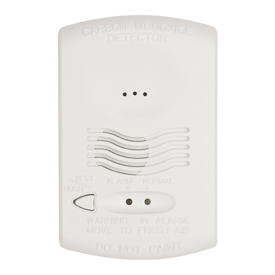
Carbon Monoxide Detector
Specifications
Electrical Specifications
System Voltage
Nominal:
Min:
Max:
Avg. Standby Current:
Max Alarm Current:
Alarm Contact Ratings:
Trouble Contact Ratings:
Audible Signal (temp 4 tone):
Max. Start-up Capacitance:
NOTICE: This manual shall be left with the owner/user of
this equipment.
This product is intended for use in ordinary indoor locations.
General Description
• Listed to UL standard 2075
• 4 wire, system monitored
• Local sounder
• Low current draw
• Alarm relay, Form C
• Trouble relay, Form A
• Dual LED's
• Test/Hush button
• SEMS wiring terminals
• Mount to single gang electrical box or surface mount to wall
or ceiling
• Optional drywall anchors included
Figure 1. Alarm Location Diagram:
BEDROOM
TO
BR
BEDROOM
KITCHEN
LIVING
ROOM
BASEMENT
–
CARBON MONOXIDE ALARM
LOCATION FOR MULTI-LEVEL RESIDENCE
SS-500-000
12/24 VDC
10 VDC
33 VDC
20 mA
40 mA (75 mA test)
30 VDC @ 0.5 A
30 VDC @ 0.5 A
85 dBA min. in alarm (at 10ft)
20 uF
BEDROOM
GARAGE
CLOSED
DOOR
Physical Specifications
Operating Temperature Range:
Operating Humidity Range:
Length:
Width:
Height:
Weight:
Wire Gauge Acceptance:
Table 1. Detector Operation Modes:
Operation
Mode
Normal
(standby)
Alarm
*Temp 4 pattern is repeated pattern of four short indications fol-
lowed by a five second pause.
When the detector has been in alarm for 30 minutes the alarm
signal will be given once every minute.
If ambient conditions return to normal, the detector will self-re-
store out of alarm and into Normal (standby) mode.
Hush feature: If required, the audible alarm can be silenced for
5 minutes by pushing the button marked "Test/Hush". The red
alarm light will continue to flash in temp-4 pattern. If carbon
monoxide is still present after the 5 minute hush period, the au-
dible alarm will sound. The hush facility will not operate at levels
above 350 ppm (parts per million) carbon monoxide.
Trouble feature: When the sensor supervision is in a trouble con-
dition (such as a sensor that has been tampered with), the detec-
tor will send a trouble signal to the panel. The detector must then
be replaced.
End of Life Timer feature: When the detector has reached the
end of its life, the trouble contact will open. This indicates that
the CO sensor inside the detector has passed the end of its life
and must be replaced. This detector's lifespan is approximately
six years from the date of manufacture. Refer to Detector Replace-
ment on page 3.
Per UL 2075, it is mandatory that a trouble signal be sent to the
panel upon CO cell trouble or cell end of life. Refer to Figure 4
for wiring of the trouble relay.
S0295-00
1
3825 Ohio Avenue, St. Charles, Illinois 60174
1-800-SENSOR2, FAX: 630-377-6495
www.systemsensor.com
0° to 40°C (32° to 104°F)
22 – 90% %RH
5.1˝
3.3˝
1.3˝
7 oz
14-22 AWG
Green
Red
LED
LED
Blink 1
-
per minute
Blink in
-
temp 4*
pattern
Sounder
-
Sound in
temp 4*
pattern
I56-3111-000
Advertisement

Related Manuals for System Sensor CO1224T


Summary of Contents for System Sensor CO1224T
- Page 1 INSTALLATION AND MAINTENANCE INSTRUCTIONS CO1224T 3825 Ohio Avenue, St. Charles, Illinois 60174 Carbon Monoxide Detector 1-800-SENSOR2, FAX: 630-377-6495 www.systemsensor.com Specifications Physical Specifications Electrical Specifications Operating Temperature Range: 0° to 40°C (32° to 104°F) System Voltage Operating Humidity Range: 22 – 90% %RH...
- Page 2 7. Test each detector as described in Testing. 8. Notify the proper authorities that the system is in operation. CAUTION Airborne dust particles can enter the detector. System Sensor rec- ommends the removal of detectors before beginning construction or any other dust producing activity.
- Page 3 Over time the sensor will lose sensitivity, and will need to drop the detector. Do not open or tamper with the detector as be replaced with a new System Sensor carbon monoxide detector. this could cause malfunction. The detector will not protect against This detector’s lifespan is approximately six years from the date...
- Page 4 − shall not be connected to a zone that signals a fire condition * Per NFPA 720 section 5.3.7, do not connect the CO1224T on a zone with other fire or intrusion initiating devices - i.e. do not connect on...
Need help?
Do you have a question about the CO1224T and is the answer not in the manual?
Questions and answers