Table of Contents
Advertisement
Quick Links
Advertisement
Table of Contents

Related Manuals for ATI Audio DDA416


Summary of Contents for ATI Audio DDA416
- Page 1 DDA416/WC106 Quad 1x4 AES/EBU Distribution Amplifier 1x6 Clock Distribution Amplifier OPERATING AND MAINTENANCE MANUAL © Copyright 2011, DaySequerra Corp. ...
-
Page 2: Table Of Contents
Table of Contents Safety I nformation 3 Unpacking 3 Installation L ocation 3 Grounding 3 Electromagnetic C apability 3 Maintenance 3 Declarations o f C onformity 3 ... -
Page 3: Safety Information
FCC CFR 47, Part 15. CE Declaration of Conformity ATI Audio Inc., West Berlin, New Jersey 08091 USA, declares that all Model DDA-416/WC106 units are in conformity with the following EU regulations and amendments: Low Voltage Directive (LVD) 2006/95/EC (replaces 73/23/EEC) -
Page 4: Air T Emperature & H Umidity
West Berlin, NJ USA, 31 July 2009 President AIR TEMPERATURE AND HUMIDITY Normal operation of this unit is warranted while operating in a temperature range of +5 to +40°C, with relative humidity ranging from 5 to 85%. Care should be taken to avoid operation outside these limits or erratic operation may result. -
Page 5: Description
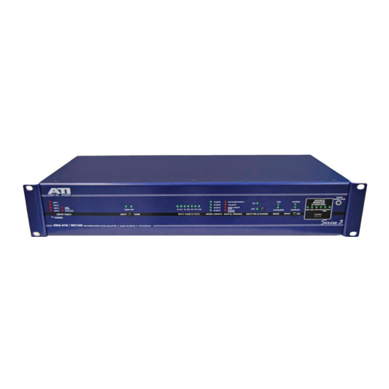
DESCRIPTION The ATI Model DDA-416/WC106 is an integrated package containing four 1X4 AES/EBU Digital Audio Distribution Amplifiers and one 1X6 Clock Distribution Amplifier. Operation of the unit is simple and straightforward, and it is housed in a rugged 2U rack mount enclosure. All audio connections are made directly to the unit’s built-in XLR and BNC connectors, and no special breakout cables or accessory jack panels are required. -
Page 6: Outputs
OUTPUTS AES/EBU XLR Outputs 1 through 4, 5 through 8, 9 through 12 and 13 through 16 operate as independent groups. Also, BNC Outputs 1 through 6 operates as a group. Each or any of these groups may be driven from the following input sources, as selected via rear panel DIP switches: ... -
Page 7: Rear Panel Connections And Switches
DIGITAL ERRORS Indicates four error conditions encountered in digital signals as an aid to troubleshooting: Bi- Phase/Parity, Validity, Non-Linear PCM and DTS-CD Signal. It displays the conditions for the channel selected with the SOURCE MONITOR AND CONTROL. INPUT RE-CLOCKING Indicates Input Re-Clocking On or Off. - Page 8 AES/EBU Input 2 Provides a balanced, transformer isolated 110 ohm AES/EBU input that may be routed to Outputs 1 – 4, 5 – 8, 9 – 12 and/or 13 – 16 via the configuration DIP switches. This input may also be routed to the six BNC outputs.
-
Page 9: Configuration Dip Switches
CONFIGURATION DIP Switches Provides routing and other selections for signal flow in the unit. See the DIP Switch Routing Table for settings: The switches are labeled left to right BANK A switch “1” is “DIP Switch 1 in the following tables. In this view Outputs 1-4 are connected to input 1. - Page 10 SOURCE SELECTION FOR AES/EBU OUTPUTS 9, 10, 11 &12 AES 1 WORD Selected SYNC CLOCK FRAME Source → INPUT 1 INPUT 2 INPUT 3 INPUT 4 CLOCK INPUT INPUT ...
-
Page 11: Block D Iagram
DDA-416 WC106 BLOCK DIAGRAM Input processing includes transformer isolation, cable termination, cable equalization, and AES digital audio interface receiver (DIR) and digital audio interface transmission (DIT). The output of each input signal processor is routed to a multiplexing chip which allows connection to each of the output groups. -
Page 12: Installation
INSTALLATION LOCATION The DDA is readily installed into a 2 RU, 19” rack. The DDA is only to be installed in an inside location where it is protected from inclement weather. Operate the DDA in temperature range of +5 to +40°C (105°F), with relative humidity ranging from 5 to 85%. -
Page 13: Specifications
DDA-416/WC106 SPECIFICATIONS INPUTS CONNECTORS XLR female for AES/EBU and AES Sync BNC for Word Clock LEVEL XLR 200 mVp-p minimum; BNC 1 Vp-p minimum Transformer isolated, balanced and floating, XLR 110Ω, BNC 75 Ω; IMPEDANCE input terminations may be switched in or out via front panel control ... -
Page 14: Warranty
One Year Limited Warranty DaySequerra warrants ATI products to be free from defects in materials and workmanship to its original owner for one (1) year from the date of purchase. DaySequerra will repair or replace such product or part thereof that upon inspection by DaySequerra, is found to be defective in materials or workmanship subject to conditions contained herein.
Need help?
Do you have a question about the DDA416 and is the answer not in the manual?
Questions and answers