Table of Contents
Advertisement
Advertisement
Table of Contents

Related Manuals for Atlas WB11


Summary of Contents for Atlas WB11
- Page 2 PRINTING CHARACTERS AND SYMBOLS Throughout this manual, the following symbols and printing characters are used to facilitate reading: Indicates the operations which need proper care Indicates prohibition Indicates a possibility of danger for the operators BOLD TYPE Important information WARNING: before operating the lift and carrying out any adjustment, read carefully chapter 7 “installation”...
-
Page 3: Table Of Contents
CONTENTS INTRODUCTION 1.1 - INTRODUCTION MACHINE IDENTIFICATION DATA 1.3 MANUAL KEEPING GENERAL INFORMATION 2.1 GENERAL SAFETY STANDARD SAFETY DVICES 2.3 INTENDED USE 2.4 GENERAL CHARATERISTICS 2.5 MACHINE DESCRIPTION 2.6 TECHNICAL SPECIFICATION TRANSPORTATION, UNPACKING AND STORAGE 3.1 TRANSPORTATION 3.2 UNPACKING 3.3 STORAGE COMMISSIONING 4.1 SPACE REQUIRED 4.2 SHAFT ASSEMBLY... -
Page 4: Introduction
CHAPTER 1 – INTRODUCTION INTRODUCTION Thank you for purchasing a product from the line of wheel balancer. The machine has been manufactured in accordance with the very best quality principles. Follow the simple instructions provided in this manual to ensure the correct operation and long life of the machine. Read the entire manual thoroughly and make sure you understand it. -
Page 5: General Information
CHAPTER 2 – GENERAL INFORMATION GENERAL SAFETY The wheel balancing machine should only be used by duly authorized and trained personnel. The wheel balancing machine should not be used for purposes other than those described in the instruction manual. Under no way should the wheel balancing machine be modified except for those modifications made explicitly by MANUFACTURER. -
Page 6: Machine Description
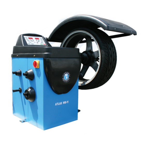
Anchor-down installation unnecessary MACHINE DESCRIPTION A: Control panel B: Wheel weight tray/cover C: Main switch D: Cone holder E: Machine body F: Feet G: Wheel guard H: Quick locking nut I: Cone adaptor J: Wheel support shaft K: Measuring gauge L: Foot brake Fig. -
Page 7: Transportation, Unpacking And Storage
CHAPTER 3 – TRANSPORTATION, UNPACKING AND STORAGE TRANSPORTATION The machine must be transported in its original packaging and kept in the position shown on the package itself. The packaged machine may be moved by means of a fork lift truck of suitable capacity. Insert the forks at the points shown in figure 2. -
Page 8: Commissioning
CHAPTER 4 – COMMISSIONING 4.1 SPACE REQUIRED When choosing the place of installation, make sure that it complies with current safety at work regulations. Do not operate the balancer while it is on the pallet. The balancer must be located on a flat floor of solid construction, preferably concrete. The balancer must sit solidly on its three feet. -
Page 9: Wheel Guard Mounting
4.3 WHEEL GUARD MOUNTING (ref. Fig. 6) Remove the wheel guard and installation Fig. 6 accessories from the package. Mount the guard frame onto the guard arms Wheel fixed on the machine. Tighten the screws. gaurd Mount the wheel guard onto the guard frame. Check the micro switch is held down when the guard is closed. -
Page 10: Control Panel And Menu Function
CHAPTER 5 – CONTROL PANEL AND MENU FUNCTION 5.1. CONTROL PANEL Press buttons only with your fingers. Never use the counterweight pincers or other pointed objects. When the beep signal is enabled, pressing of any push button is accompanied by a “Beep”. -
Page 11: Menu Functions
20. Push button, FUNCTION selection 21. Push button, SPLIT selection (*) 22. Push button, ALU/ ALU mode selection (*) 23. Push button, STATIC/MOTORCYCLE WHEEL mode selection (*) those functions are disabled in this model. MENU FUNCTIONS (figure 8) OPT function DIAMETER mm/inch WIDTH... -
Page 12: Operation Of The Wheel Balancer
CHAPTER 6 – OPERATION OF THE WHEEL BALANCER Do not use the machine until you have read and understood the entire manual and the warning provided. The wheel guard must not be opened before the wheel stops. The STOP button serves to stop the machine immediately in emergencies. - Page 13 On most wheels, the inner side of the wheel hub usually has the most uniform surface for wheel balancing. Always center the wheel by the most uniform shaped side of the hub to achieve the most accurate balance. Regardless of mounting type, always make sure that the wheel is forced firmly against the shaft faceplate and that the quick locking nut is tightened.
-
Page 14: Wheel Data Entry
WHEEL DATA ENTRY Before balancing a wheel, wheel data must be entered into the processor. 6.3.1 WHEEL DATA A: The distance, measured from the machine to the inner side of the rim B: The wheel width D: The wheel diameter Fig. -
Page 15: Balancing Mode
BALANCING MODE 6.4.1 DYNAMIC MODE The dynamic mode is used for most passenger and light truck wheels using the most common location for corrective weights. Clip-on weights are placed on the inner and outer sides of the rim. On the initial screen press Fig. -
Page 16: Standard Alu Mode
6.4.3 STANDARD ALU MODE All the ALU modes are dynamic balance. Choose the option that best fits the available locations as shown in the figure 16. From the measurement screen, press to select the modes ALU1 ALU2 ALU3 ALU4. Fig. 16 Balancing of light alloy rims with application of adhesive weights on the rim shoulders. -
Page 17: Unbalance Optimization (Opt)
6.4.4 UNBALANCE OPTIMIZATION (OPT) This function is used to determine the best mating of tire and rim that will result in the least amount of total unbalance of the wheel. It severs to reduce the amount of weight to be added in order to balance the wheel. -
Page 18: Set Up
CHAPTER 7 – SET UP SELF-DIAGNOSIS Fig. 17 Diagnosis of phase Rotate the wheel in direction of rotation, the readouts display from 0 to 255. Rotate the wheel in reverse direction of rotation, the readouts displays from 255 to 0. Diagnosis of inner piezo Push the balancing shaft from any direction, the readouts change. -
Page 19: Self-Calibration
SELF-CALIBRATION To access SELF-CALIBRATION menu, refer to Fig. 8. For the self-calibration proceed as follows: Make sure to entry the exact date of the wheel mounted. Entry of incorrect data would mean that the machine is not correctly calibrated, therefore all subsequent measurements will be incorrect until the new self-calibration is performed with the correct data. -
Page 20: Maintenance
CHAPTER 8 – MAINTENANCE GENERAL WARNINGS Unauthorized personnel may not carry out maintenance work. Regular maintenance as described in the manual is essential for correct operation and long lifetime of the tire changer. If maintenance is not carried out regularly, the operation and reliability of the machine may be compromised. -
Page 21: Errors And Trouble-Shooting
CHAPTER 9 – ERRORS AND TROUBLE-SHOOTING ERROR DISPLAY During machine operation, various cause of faulty operation can occur. If defected by the micro- processor, they appear on the display as follows: ERRORS: MEANING: SOLUTION: Err -0- The machine is not preset up by the Call for the technical service. -
Page 22: Electric Diagram
CHAPTER 10 – ELECTRIC DIAGRAM (+) red -)black (+) red -)black 22 / 22 REV. 03... - Page 23 The limited one (1) year warranty does not include a labor warranty. Warranties do not apply to items that have been abused or misused. Returned goods must be authorized to be returned (in writing) by Atlas Automotive Equipment ®...
Need help?
Do you have a question about the WB11 and is the answer not in the manual?
Questions and answers
Rim sizes in millimeters. And I need it to be in inches.
The rim sizes for the Atlas WB11 are 10" to 26" in inches and approximately 254 mm to 660 mm in millimeters.
This answer is automatically generated
The right side of the screen has gone black, left side still works
Possible causes for the right side of the screen going black on an Atlas WB11 include:
1. No power to the machine – check if the power is on.
2. Faulty power plug – replace it.
3. Disconnected electrical wires – reconnect the wires.
4. Incorrect power voltage – check and correct the voltage.
5. Blown fuses – replace the fuses.
These issues may affect the display and could cause part of the screen, such as the right side, to go black.
This answer is automatically generated