Table of Contents
Advertisement
Advertisement
Table of Contents

Related Manuals for Whistler WBU-900


Summary of Contents for Whistler WBU-900
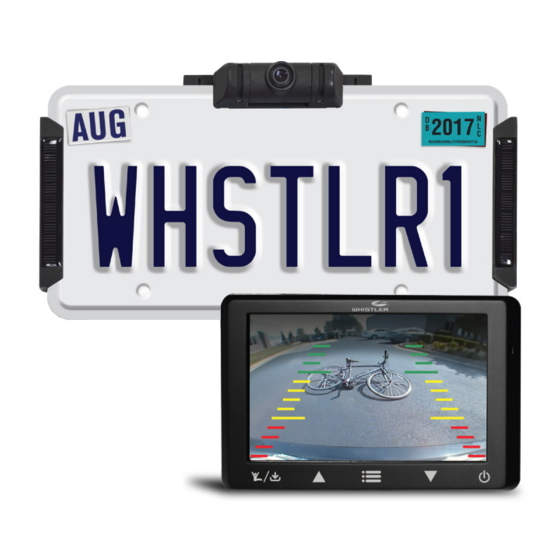
- Page 1 WBU-900 / WBU-900C User Guide WIRELESS DIGITAL BACKUP CAMERA INSTALLS IN MINUTES...
- Page 2 INTRODUCTION Welcome Thank you for choosing a Whistler product. We are dedicated to providing products that represent both quality and value. Please read the User Guide carefully before using this product. If you have additional questions visit our website at www.whistlergroup.com...
-
Page 3: Table Of Contents
TABLE OF CONTENT Components .................. 4 Getting Started ................5 Assembly / Installation ............. 6-8 Camera Angle ................9 Monitor Mount ................10 Operation ................11-12 Function ..................13 Monitor Settings ..............14-15 Information.................. 16 Troubleshooting ................. 17 Disclaimer ..................18 Care and maintenance .............. -
Page 4: Components
COMPONENTS Monitor 10. 2 short machine screws Camera 11. 2 machine nuts Solar cell 12. 2 cushions Suction cup mount 13. 4 cable tie mount Dash Disk 14. 4 spacers Tie wraps 15. Power cord License back-plate 16. USB cord 4 long screws (Domestic) 4 long screws (Import) -
Page 5: Getting Started
GETTING STARTED Remove camera assembly from box and make sure all components are included. Charge the camera: 1. Connect the supplied USB cord to the micro USB port of the camera assembly. 2. Plug the USB cable into any standard USB charger with an output rating of 500ma or higher. -
Page 6: Assembly / Installation
ASSEMBLY / INSTALLATION IMPORTANT: As license plate tolerances vary slightly in width and height, it is important that you follow the steps as outlined below: Remove license plate from vehicle and place on top of the supplied license back plate. Insert 2 short machine screws into 2 of the mounting holes and finger tighten 2 machine nuts onto them in order to hold the plates together for steps 3 thru 5. - Page 7 ASSEMBLY / INSTALLATION Remove the 2 short machine screws and nuts used earlier and set aside. Peel the backing from the adhesive disks and apply one spacer over each license plate mounting hole. Adhesive disks backing Apply pressure to set the adhesive tape. If two of the license plate mounting holes are not required for attachment to your vehicle, insert the short machine screws and tighten with the supplied machine...
-
Page 8: Assembly / Installation
ASSEMBLY / INSTALLATION 11. Connect the solar panel connectors to the mating connectors from the main camera housing and place the tie wrap adhesive pads as shown. Use 2 tie wraps to neatly hold the cables in place and cut the excess length of the tie wrap if desired. -
Page 9: Camera Angle
CAMERA ANGLE The camera angle should be adjusted to provide an optimal view of objects behind the vehicle. Adjust the camera angle as required: • To adjust the camera angle, tilt the camera to the correct angle. • The camera should be adjusted to a horizontal position relative to the ground, so as to provide optimal view of objects behind the vehicle. -
Page 10: Monitor Mount
MONITOR MOUNT Find a mounting surface inside the vehicle for the monitor where it can be easily seen, and does not obstruct your vision when driving. NOTE: To maximize the effectiveness of the suction mount, the mounting location surface temperature should be between 50°... -
Page 11: Operation
OPERATION Testing the System With power applied to the monitor, the button backlight will illuminate to indicate the monitor is ON and in Standby mode. The Blue LED will blink briefly to indicate that it is attempting to communicate with the camera. When connected to the camera, the blue LED will turn solid. -
Page 12: Operation
OPERATION If your 12-volt DC power port is switched on with your ignition, the unit will automatically request an image from the backup camera each time you start your vehicle. When the vehicle is shut off, power is removed from the monitor and the button backlight will shut off. -
Page 13: Function
FUNCTION Functions of the Touch Buttons (left to right) : Touch to enable or cancel the transmitter; touch for 3 seconds to turn on/off the backup assist lines. Touch to select a corresponding function. : Touch to move to or adjust a corresponding function : Touch to enable/cancel the menu. -
Page 14: Monitor Settings
MONITOR SETTINGS Menu Operations: Enter the main Menu Interface and 4 options are available including Image Parameters, Image Rotation, SETUP and Software Information. Press to select corresponding option, and then touch the button to enter the option: Image Parameters (Brightness, Contrast, Color) Setting Interface are shown above:... - Page 15 MONITOR SETTINGS Brightness/Contrast/Color Settings are similar. Take Brightness as an example, when Brightness is chosen, press the interface to adjust the brightness as shown above: Select “Image Rotation”, and then touch the button to rotate or mirror the image. (It is best to have a video image displayed when making this selection).
-
Page 16: Information
INFORMATION Battery Icon is on the top left corner of the monitor, and indicates the relative capacity of the built-in lithium battery when a video image is present. Signal strength of the received image is on the top right corner of the monitor when a video image is present. The Camera and Video Transmitter: The Camera / Video transmitter is equipped with the built-in rechargeable lithium battery and is connected with two solar... -
Page 17: Troubleshooting
TROUBLESHOOTING If the monitor does not turn on when power is applied: • Check to make sure the power source is active (if your cigarette lighter is switched with vehicle ignition, your monitor will only work when the vehicle is running or the key in the ON position). -
Page 18: Disclaimer
Whistler Digital Wireless Backup Camera, you agree that you are solely responsible for the operation of your vehicle and that The Whistler Group is not responsible for any property damage, personal injury, or loss of life that may result from the operation of your vehicle. -
Page 19: Care And Maintenance
CARE AND MAINTENANCE Cleaning Do not clean or wipe the Back-Up Camera with solvents or chemical materials. If necessary, remove dirt or stains using a soft cloth dampened with a mild detergent solution. Fuse Replacement 1. Turn the cap on the tip of the power plug counterclockwise (no tools needed). -
Page 20: Fcc And Ic Information
FCC AND IC INFORMATION IMPORTANT: FCC (Federal Communications Commission) requirements state that changes or modifications not expressly approved by Whistler could void the user’s authority to operate the equipment. FCC Part 15.19 Warning Statement This device complies with part 15 of the FCC rules. Operation is... -
Page 21: Fcc And Ic Information
FCC AND IC INFORMATION RF warning statement: The device has been evaluated to meet general RF exposure requirement. To maintain compliance with FCC's RF exposure guidelines, this equipment should be installed and operated with a minimum distance of 20cm between the radiator and your body. FCC ID : HSXBU01M / HSXBU01C IC Warning: This device complies with Industry Canada licence-exempt RSS... -
Page 22: Specifications
SPECIFICATIONS CAMERA Operational Current (when transmitting): <220mA Pixels: 640 x 480 View Angle: 110° Image Sensor: 1/4“ CMOS VGA Image Quality: Max 25 fps. Camera Assembly: IP65 TRANSMITTER Frequency: 2400 2485.5MHz RF transmission distance: >328 ft. (>100 m) Operation/storage temperature: 14° to 122°F (-10° to 50°C) MONITOR LCD display screen size: 4.3 in. -
Page 23: Warranty Information
All express or implied warranties for this product are limited to one (1) year. Whistler is not liable for damages arising from the use, misuse, or operation of this product including but... - Page 24 Due to the specialized equipment necessary for testing Whistler products, there are no authorized service centers other than Whistler. When returning a unit for service under warranty, please follow these instructions: Ship the unit in the original carton or in a suitable sturdy equivalent, fully insured, with return receipt requested to: Whistler Repair Dept.
- Page 25 WARRANTY INFORMATION IMPORTANT: Whistler will not assume responsibility for loss or damage incurred in shipping. Therefore, please ship your unit insured with return receipt requested. CODs will not be accepted! Include with your unit the following information, clearly printed: • Your name and physical street address for shipping (no PO Boxes), a daytime telephone number, and an email address (if applicable).
- Page 26 $65.00. Payment may also be made by MasterCard, VISA or American Express. Personal checks are not accepted. In the event repairs cannot be covered by the minimum service fee, you will be contacted by a Whistler technical service specialist who will outline options available to you.
- Page 27 (if applicable). Customer Service If you have questions concerning the operation of your Whistler product, or require service during or after the warranty period, please call Customer Service at Toll Free (800)531-0004...
- Page 28 CORPORATE HEADQUARTERS 1716 SW Commerce Dr. Ste. 8 Bentonville, AR 72712 Toll Free (800) 531-0004 TEL (479) 273-6012 www.whistlergroup.com CUSTOMER RETURN CENTER 1412 South 1st St. Rogers, AR 72756 Email: info@whistlergroup.com 07F17 © 2017 The Whistler Group, Inc.
Need help?
Do you have a question about the WBU-900 and is the answer not in the manual?
Questions and answers
The suction cup on my dash mount has broken off. I was wondering if I could get a new one?
The section cup on my dashmount has broken. I was wondering if I could get a new one?
Someone donated a camera to our senior center but no one has the code to install it. How can we get a code to make it work?
The Whistler WBU-900 camera requires an Activation Code to function. The product may not work without one. To obtain the Activation Code, check the product packaging or manual. If it is not included, contact the seller or manufacturer for assistance.
This answer is automatically generated
@Mr. Anderson , i understand they have gone out of business and therefore wehave been able to get the activation code