Table of Contents
Advertisement
■ XP-3110
(Combustible gases and vapors detector)
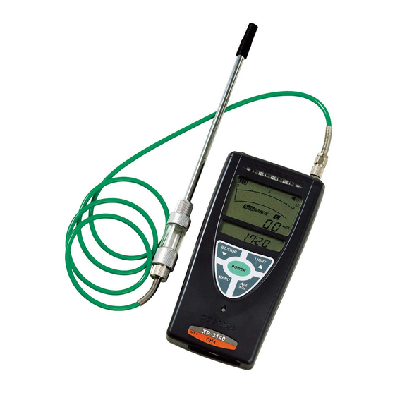
■ XP-3140
(High concentration gas detector)
■ XP-3160
Portable Gas Detector
Instruction Manual
This instruction manual explains to the use of three models listed on the left
● Please keep this instruction manual available for quick reference when
needed
● Before use, carefully read this instruction manual and fully understand the
content.
Specifications No.: XP-3000T
Advertisement
Table of Contents

Related Manuals for Cosmos XP-3110

Summary of Contents for Cosmos XP-3110
- Page 1 Portable Gas Detector ■ XP-3110 (Combustible gases and vapors detector) Instruction Manual ■ XP-3140 (High concentration gas detector) This instruction manual explains to the use of three models listed on the left ■ XP-3160 ● Please keep this instruction manual available for quick reference when needed ●...
-
Page 2: Table Of Contents
Table of Contents Contents of This Package …………………………………………… 1. Introduction ………………………………………………………… Explosion-proof Precautions ………………………………………………………………………………… Explanation of Symbols ……………………………………………………………………………………… Safe Operation ………………………………………………………………………………………………… 2. Component Names and Functions …………………………… 3. Operating Procedure ……………………………………………… Procedure ……………………………………………………………………………………………………… Gas Alarm ……………………………………………………………………………………………………… Functions and Settings Methods …………………………………………………………………………… Peak Hold Settings ……………………………………………………………………………………………... -
Page 3: Contents Of This Package
The following standard components are packed together with the Gas Detector. Carefully check the contents against the list when unpacking. If any components are missing or damaged, contact your New-Cosmos Electric representative. A replacement for the missing or damaged component will be sent to you. -
Page 4: Introduction
Follow the explosion-proof XXXXXXXXXX. Operating conditions: Replace batteries only in area know to be NON-HAZARDOUS. ● Use the Gas detector in the carrying case specified by New-Cosmos Electric. ● As a comprehensive measure for the prevention of danger resulting from static electricity. ●... -
Page 5: Safe Operation
Introduction 1. Introduction (continued from previous page) ■ Safe Operation In order to use the Gas Detector safely, be sure to observe the following items. DANGER If the gas alarm turns ON, immediately take all necessary measures to ● prevent explosion accidents. WARNING Be sure to turn ON the Gas Detector in clean air. -
Page 6: Component Names And Functions
Component Names and Functions 2. Component Names and Functions (10) (11) Name Function Alarm lamp Flashes at the time of gas alarming. Gas sampling pipe connection port Connects to the gas sampling hose. Exhaust port Exhausts sampled gas. Buzzer opening Sounds a buzzer. - Page 7 Component Names and Functions 2. Component Names and Functions (continued from previous page) Name Function LCD main screen Displays gas concentration and a variety of messages. A. Displays gas concentration. B. Displays the unit of measurement. C. Displays the remaining battery level. D.
- Page 8 Component Names and Functions 2. Component Names and Functions (continued from previous page) 1-m gas sampling hose Name Function Gas sampling hose Leads gas to the Gas Detector. (1 m long) Coupler Connects to the Gas Detector. Prevents the penetration of water and dust into the Gas Detector. Drain filter (DF-4) The filter element (FE-2) is mounted.
-
Page 9: Operating Procedure
Operating Procedure 3. Operating Procedure ■ Procedure Be sure to conduct a daily inspection before WARNING performing detection work (see page 21). Insert Turn ON Displays the gas Warms Turn OFF the Procedure t h e G a s concentr a tion Detects Gas Detector batteries. - Page 10 Operating Procedure 3. Operating Procedure (continued from previous page) 3. Detection Gas Concentration Screen ● Gas is detectable when the gas concentration screen is displayed. The LCD sub screen will display Time. → Refer to page 10 for information on the gas alarm. 〈Gas Concentration Screen〉...
- Page 11 Operating Procedure 3. Operating Procedure (continued from previous page) Zero adjustment ● To conduct zero adjustment, press the AIRADJ. switch for approximately three seconds. The buzzer will then beep once, followed by two beeps after a short pause. If zero adjustment fails, the buzzer will beep once followed by continuous beeps.
-
Page 12: Gas Alarm
Operating Procedure 3. Operating Procedure (continued from previous page) 3. Turning Power OFF CAUTION To turn OFF the Gas Detector, wait until the gas concentration drops in a clean air. When the POWER switch is pressed for approximately three seconds, the buzzer beeps, and the Gas Detector will be turned OFF. -
Page 13: Functions And Settings Methods
Operating Procedure 3. Operating Procedure (continued from previous page) ■ Functions and Setting Methods Press the MENU switch for approximately three seconds on the gas concentration screen. The buzzer will beep once, followed by two beeps after a short pause, and the following settings can be made and executed. -
Page 14: Peak Hold Settings
Operating Procedure 3. Operating Procedure (continued from previous page) ■ Peak Hold Settings With the peak hold function set, the peak value of gas concentration detected will be displayed continuously. (1) Press the MENU switch for approximately three seconds while the gas concentration screen is displayed to display the peak hold setting screen (see page 11). -
Page 15: Alarm Buzzer Silence Settings
Operating Procedure 3. Operating Procedure (continued from previous page) ■ Alarm Buzzer Silence Settings If the alarm buzzer is muted, the alarm buzzer will not sound when the gas concentration reaches the alarm level. (1) Press the MENU switch for approximately three seconds to display the alarm buzzer silence screen. -
Page 16: Changing The Sample Gas
Operating Procedure 3. Operating Procedure (continued from previous page) ■ Changing the Sample Gas Take the following steps to select the type of sample gas if there are two or more detectable gases. (1) Press the MENU switch for approximately three seconds while the gas concentration screen is displayed to display Flashes the sample gas selection screen. -
Page 17: Logging
Operating Procedure 3. Operating Procedure (continued from previous page) ■ Logging Take the following steps to log the detected gas. Logger capacity (1) Press the MENU switch for three seconds while the gas concentration screen is displayed to display the logging start screen. -
Page 18: Data Logger Communications Screen
Operating Procedure 3. Operating Procedure (continued from previous page) ■ Data Logger Communications Screen Take the following steps to read logging data. In order to read data, a personal computer (see page 1) and Log Data Collection Set (optional item) are required. -
Page 19: Time Settings
Operating Procedure 3. Operating Procedure (continued from previous page) ■ Time Settings (1) Press the MENU switch for three seconds while the gas concentration screen is displayed to display the time setting screen. Refer to page 11. (2) Press the MENU switch to make time settings. The CL5 indication will then start flashing. -
Page 20: Error Message (Malfunction Alarm)
Detector is turned OFF and ON several times in a clean air, a sensor error or the end of the sensor lifetime may be considered. Contact your New-Cosmos Electric representative for repairs. This message appears when the battery voltage drops and the remaining battery level is low. -
Page 21: Replacement Of Consumable Parts
WARNING If water is drawn into the inside of the Gas Detector, the Gas Detector cannot detect properly. Contact your New-Cosmos Electric representative for repairs. (1) Remove the filter case of the drain filter. -
Page 22: Battery Replacement
Replacement of Consumable Parts 5. Replacement of Consumable Parts (continued from previous page) ■ Battery Replacement When the battery voltage drops and the battery is almost exhausted, the message Err-b will appear and the Gas Detector will not work. Replace the batteries. WARNING Use Panasonic LR6XJK, Toshiba One Screw... -
Page 23: Maintenance Inspection
ON again. if "Err-P" is not displayed the damage of the gas sampling pipe or the airtight defect of the sensor packing or pump diaphragm may be considered. Contact your New-Cosmos Electric representative for repairs or replacements. ■ Regular Inspection In order to maintain the accuracy of the Gas Detector, request a regular inspection from your New- Cosmos Electric representative. -
Page 24: Troubleshooting
Troubleshooting 7. Troubleshooting Before requesting repairs, please check the items in the following table. (When the instrument fails to operate, remove all batteries. After several minutes, install the batteries and try again.) ■ Gas detector Page for Symptom Cause Treatment reference T h e p o l a r i t y i s Install batteries again in the... -
Page 25: Warranty
New Cosmos’s sole option, replacement or repair of such non-conforming product or refund of the original purchase price of the non-conforming product. In no event will New Cosmos be liable for any other special, incidental or consequential damages or losses of any kind whatsoever, including but not limited to, loss of anticipated profits and any other loss caused by reason of non-operation of the product. -
Page 26: Specifications
■ Gas Detector Product Combustible Gas Detector High-concentration Gas Detector High-sensitivity Gas Detector Model XP-3110 XP-3140 XP-3160 Manufacturing gas, natural gas, methane, hydrogen, C o m b u s t i b l e g a s a n d... -
Page 27: Markings Of Explosion-Proof
Markings of explosion-proof 10. Markings of explosion-proof 1. Product mark detail 2. Um value mark detail Display each model XP-3110 XP-3140 XP-3160 3. Warning sticker (for leathercase) detail 4. Warning sticker (for body) detail List of hazardous locations standards with issue dates:... -
Page 28: Detection Principle
Detection Principle 11. Detection Principle ● Catalytic Combustion Type A catalyst applied to the surface of a platinum coil causes catalytic combustion on the surface of the catalyst even when the gas concentration level in lower than the lower explosion limit. The temperature rise in this process increases the electrical resistance of platinum coil. -
Page 29: Glossary
Glossary 12. Glossary Zero adjustment: Zero-point setting in pure air (21 vol% adjustment for Oxygen) Explosion-proof: A structure applied to electrical equipment to prevent the equipment from igniting the surrounding explosive atmosphere as the source of ignition. Intrinsically safe design: A structure whose inability to ignite explosive gases with a spark of electricity or a hot section generated in normal time or an accident has been confirmed in fire and other tests. - Page 30 MEMO...
- Page 32 ● Loss of the Instruction Manual: If this instruction manual is lost, contact New Cosmos Electric or the nearest branch or sales office shown below. A copy of the instruction manual will be delivered to you. (A fee is charged.) Distributor/Retail Store XP-3000ATEXETC (01)0000.000...
Need help?
Do you have a question about the XP-3110 and is the answer not in the manual?
Questions and answers