Advertisement
Quick Links
Part Number
Port One - Copper Port Two - Duplex Fiber-Optic
E-TBT-FRL-05
RJ-45, 10Base-T
E-TBT-FRL-05(HT)
100 m (328 ft)*
E-TBT-FRL-05(SC)
RJ-45, 10Base-T
E-TBT-FRL-05(SCHT)
100 m (328 ft)*
E-TBT-FRL-05(MT)
RJ-45, 10Base-T
100 m (328 ft)*
E-TBT-FRL-05(SM)
RJ-45, 10Base-T
100 m (328 ft)*
E-TBT-FRL-05(SMHT) RJ-45, 10Base-T
100 m (328 ft)*
E-TBT-FRL-05(L)
RJ-45, 10Base-T
100 m (328 ft)*
E-TBT-FRL-05(LH)
RJ-45, 10Base-T
100 m (328 ft)*
E-TBT-FRL-05(XC)
RJ-45, 10Base-T
E-TBT-FRL-05(XCHT)
100 m (328 ft)*
E-TBT-FRL-05(XLHT) RJ-45, 10Base-T
100 m (328 ft)*
* Typical maximum cable distance. (Actual distance is dependent upon the
physical characteristics of the network installation.)
USER'S GUIDE
E-TBT-FRL-05
Stand-Alone Media Converter
• Ethernet™
• Copper to Fiber
• 10Base-T to 10Base-FL
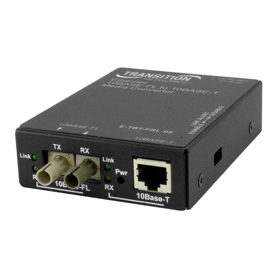
Transition Networks E-TBT-FRL-05
series Ethernet™ 10Base-T to 10Base-FL
Media Converters connect 10 Mb/s
twisted-pair copper cable to 10 Mb/s
fiber-optic cable.
ST, 10Base-FL, 850 nm multimode
2 km (1.2 miles)*
SC , 10Base-FL, 850 nm multimode
2 km (1.2 miles)*
MT-RJ , 10Base-FL, 850 nm multimode
2 km (1.2 miles)*
ST, 10Base-FL, 1300 nm singlemode
20 km (12.4 miles)*
ST, 10Base-FL, 1300 nm singlemode
2 km (1.2 miles)*
ST, 10Base-FL, 1300 nm multimode
5 km (3.1 miles)*
ST, 10Base-FL, 1300 nm multimode
40 km (24.9 miles)*
SC, 10Base-FL, 1300 nm singlemode
20 km (12.4 miles)*
SC, 10Base-FL, 1300 nm singlemode
50 km (31.1 miles)*
Installation . . . . . . . . . . . . . . . . . .2
Operation . . . . . . . . . . . . . . . . . . .4
Technical Specifications . . . . . . . .4
Cable Specifications . . . . . . . . . . .5
Fault Isolation and Correction . . .6
Contact Us . . . . . . . . . . . . . . . . . .7
Compliance Information . . . . . . . .8
E-TBT-FRL-05
Optional Accessories: (sold separately)
Part Number
Description
E-MCR-03
12-Slot Media Converter Rack (includes universal internal power
supply) 17 x 15 x 5 in. (432 x 381 x 127 mm)
WMBS
Optional Wall Mount Brackets
Length: 3.2 in. (81 mm), Fits converter length: 3.9 in. (99 mm)
SPS-1872-SA
Optional External Power Supply; 18-72VDC Stand-Alone
Output: 12.6VDC, 1.0 A
SPS-1872-CC Optional External Power Supply; 18-72VDC Piggy-Back
Output: 12.6VDC, 1.0 A
INSTALLATION
Set the LinkAlert™ Switch
The LinkAlert™ switch is located on the side of the
Media Converter.
Use a small flatblade
screwdriver or a similar device to set the recessed
switches (see page 3).
LEFT
Enables the LinkAlert™ function
RIGHT
Disables the LinkAlert™ function.
Install the Cable
FIBER
1.
Locate or build 10Base-FL compliant fiber cable with male, two-stranded
TX to RX connectors installed at both ends.
2.
Connect the fiber cables to the J/E-CF-02 Media Converter as described:
•
Connect the male TX cable connector the female TX port.
•
Connect the male RX cable connector to the female RX port.
3.
Connect the fiber cables to the other device (another media converter,
hub, etc.) as described:
•
Connect the male TX cable connector the female RX port.
•
Connect the male RX cable connector to the female TX port.
Connect the fiber cable
to the Media Converter
as shown.
RX
TX
2
Tech Support: 1-800-260-1312 Int'l: 00-1-952-941-7600 7am-6pm CST (GMT-6:00)
TM
LinkAlert
Enabled
TM
LinkAlert
Disabled
Connect the fiber cable
to the other device
(media converter,
hub, etc.) as shown
RX
TX
Advertisement

Related Manuals for Transition Networks E-TBT-FRL-05


Summary of Contents for Transition Networks E-TBT-FRL-05
- Page 1 Output: 12.6VDC, 1.0 A • Copper to Fiber • 10Base-T to 10Base-FL SPS-1872-CC Optional External Power Supply; 18-72VDC Piggy-Back Output: 12.6VDC, 1.0 A Transition Networks E-TBT-FRL-05 series Ethernet™ 10Base-T to 10Base-FL Media Converters connect 10 Mb/s INSTALLATION twisted-pair copper cable to 10 Mb/s fiber-optic cable.
-
Page 2: Technical Specifications
Data Rate 10 Mb/s Case Dimensions 3.9" x 3.0" x 1.0" (99mm x 76mm x 25mm) Consult the User’s Guide for the Transition Networks SPS1872-xx DC External Shipping Weight 2 lbs (0.9 kg) Power Suppy for powering the Media Converter. -
Page 3: Cable Specifications
62.5/125 µm Multimode fiber (optional): 100/140, 85/140, 50/125 µm • Is the power adapter the proper voltage and frequency for AC outlet? E-TBT-FRL-05, E-TBT-FRL-05(SC) NOTE: Refer to “Power Supply Requirements” on page 7. E-TBT-FRL-05(MT) 850 nM multimode • Is the power adapter properly installed in the Media Converter and in Fiber Optic Transmitter Power: min: -20.0 dBm... - Page 4 Regulation: EMC Directive 89/336/EEC All trademarks and registered trademarks are the property of their respective owners. Purpose: To declare that the E-TBT-FRL-05 to which this declaration refers is in Copyright Restrictions conformity with the following standards. © 2003 Transition Networks.
Need help?
Do you have a question about the E-TBT-FRL-05 and is the answer not in the manual?
Questions and answers