Advertisement
Quick Links
This quick start guide explains how to quickly set up and activate your McAfee
NS-series Sensor in in-line mode.
All product documentation referenced in this quick start guide is found on the McAfee Service Portal.
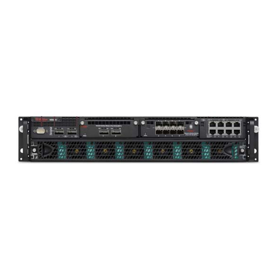
The NS9100/NS9200 Sensor model
Figure 1 Sensor front panel
Console port (1)
1
QSFP+ 40 Gigabit Ethernet ports (2)
2
Two slots for I/O modules (Any combination of the interface modules can be used)
3
•
QSFP+ 40 Gigabit Ethernet ports (4)
•
QSFP+ 40 Gigabit Ethernet ports (2)
McAfee
Network Security Platform
®
NS9x00 Quick Start Guide
Network Security Platform
®
Revision E
1
Advertisement

Subscribe to Our Youtube Channel
Related Manuals for McAfee NS9100


Summary of Contents for McAfee NS9100
- Page 1 This quick start guide explains how to quickly set up and activate your McAfee Network Security Platform ® NS-series Sensor in in-line mode. All product documentation referenced in this quick start guide is found on the McAfee Service Portal. The NS9100/NS9200 Sensor model Figure 1 Sensor front panel Console port (1)
- Page 2 USB ports (2) RJ-45 100/1000/10000 Management port (Mgmt) (1) Power supply A (Pwr A) RJ-45 100/1000/10000 Response port (R1) (1) Power supply B (Pwr B) (optional on NS9100) RJ-45 Auxiliary port (Aux) (1) The NS9300 Sensor model Figure 3 Sensor front panel...
- Page 3 The NS9300 Sensor consists of a Primary Sensor, NS9300P, and a Secondary Sensor, NS9300S. Console ports on the NS9300P and NS9300S Sensors (2) QSFP+ 40 Gigabit Ethernet Interconnect ports (4). G0/1 and G0/2 on NS9300P Sensor and G4/1 and G4/2 on NS9300S Sensor.
- Page 4 The following accessories are shipped in the NS-series Sensor crate: • Sensor • Power supply • Power cords. McAfee provides a standard and international power cables. • Set of rack mounting rails • Printed Quick Start Guide Verify the hardware and software requirements The following hardware requirements are to be met.
- Page 5 The following software are to be installed. • Sensor image • Manager image • Signature set Install the slide rails Follow this procedure to assemble the slide rails and position the Sensor on it. Task Rack installation - Remove inner member from slides front bracket inner member outer member...
- Page 6 Rack installation - Install slides to rack Align brackets to desired vertical position on the rack and insert the fasteners. Move the ball retainer to the front of slides. Do not handle the NS-series appliance by the mounting brackets Chassis installation - Install inner member to chassis Align inner member key holes to standoffs on chassis, move inner member following the direction the picture.
- Page 7 Chassis installation - Install chassis to fixed slides Pull the release button in the inner member to release the lock and allow the chassis to close. Chassis removal - Extend slides Fully extend the slides until it is in the locked position, pull the release button to release lock and disconnect inner member from slides.
- Page 8 Chassis removal - Remove inner member from chassis Press safety locking pin to release inner member from chassis. While installing NS9300, this procedure is to be followed for both the primary and the secondary Sensors. Install the interface modules You can purchase the following interface modules and insert them into the relevant slots on your NS-series Sensor.
- Page 9 Task Plug a Category 5e Ethernet cable in the Management port (labeled Mgmt): on the rear panel of the NS9100 and NS9200 Sensors. on the rear panel of the NS9300P Sensor. Plug the other end of the cable into the network device connected to your Manager server.
- Page 10 Plug the DB9 Console cable(s) into the Console port (labeled Console): on the front panel of the NS9100 and NS9200 Sensors. on the front panel of the NS9300P and NS9300S Sensors. Connect the other end of the Console port cable directly to a COM port of the PC or terminal server you will be using to configure the Sensor (for example, a PC running correctly configured Windows Hyperterminal software).
- Page 11 Cable the Interconnect ports This procedure describes how to connect the NS9300P Sensor to the NS9300S Sensor. Task Plug the supplied 40G Direct Attach cable into port G0/1 of the NS9300P Sensor and connect the other end of the cable into port G4/1 of the NS9300S Sensor. Plug the supplied 40G Direct Attach cable into port G0/2 of the NS9300P Sensor and connect the other end of the cable into port G4/2 of the NS9300S Sensor.
- Page 12 Windows server during this process. Following steps briefly explain the Manager installation: Task Prepare the system according to the requirements outlined in McAfee Network Security Platform Installation Guide and the McAfee Network Security Platform Release Notes. Close all open applications.
- Page 13 To add a Sensor in the Manager, click Device List | Devices, and then click New. You do not require a license file to enable IPS on NS-series Sensors. The Add New Device page is displayed. Enter the following mandatory information in the appropriate fields. •...
- Page 14 The shared secret must be a minimum of 8 characters and maximum of 25 characters in length. The key cannot start with an exclamation mark nor can have any spaces. The parameters that you can use to define the key are: •...
- Page 15 Optional, but recommended. Change the Sensor password. At the prompt, type: passwd.The Sensor prompts you to enter the new password and prompts you for the old password. A password must contain between 8 to 25 characters, is case-sensitive, and can consist of any alphanumeric character or symbol.
- Page 16 Verify successful installation Task In the Sensor CLI, type: status. The status report appears. The Sensor parameter System Initialized should be yes, and for Manager communication Trust Established should be yes. Return to the Manager. In the Manager Home page, view the Manager status in the System Health section. The Manager status should be up and Sensor status should be active.
- Page 17 Sensor automatically blocks the attack. To tune this or any other McAfee-provided policies, you can clone the policy and then customize it as described in the McAfee Network Security Platform IPS Administration Guide.
- Page 18 If you need to contact Technical Support, go to https://mysupport.mcafee.com. Copyright © 2017 McAfee, LLC McAfee and the McAfee logo are trademarks or registered trademarks of McAfee, LLC or its subsidiaries in the US and other countries. Other marks and brands may be claimed as the property of others.
Need help?
Do you have a question about the NS9100 and is the answer not in the manual?
Questions and answers