Table of Contents
Advertisement
Quick Links
Advertisement
Table of Contents

Related Manuals for HeartWare HVAD Pump

Summary of Contents for HeartWare HVAD Pump
- Page 1 HeartWare HVAD ™ ™ System Instructions for Use...
-
Page 3: Table Of Contents
™ ™ HVAD Controller Connections ..................65 ® HVAD Controller ....................... 69 ® Using the HeartWare Batteries ..................73 ® Using the HeartWare Battery Charger ................79 ® Using the HVAD Controller AC Adapter or DC Adapter ..........82 ®... - Page 4 5.0 Using the HeartWare Monitor ........................ 85 ® 5.1 General Overview ......................85 5.2 Informational Screens ......................87 5.3 System Screens ........................89 5.4 Downloading Controller Log Files ................... 100 5.5 Updating Software on the HVAD Controller ..............101 ®...
-
Page 5: Introduction
Clinical users of the HeartWare HVAD System should ™ ™ attend HeartWare training, should have a working knowledge of the principles of ventricular assist devices 1.4 Warnings ......3 (VADs), and should be aware of the physical and psychological needs of patients undergoing VAD support. -
Page 6: Introduction
The HeartWare HVAD System is designed ™ ™ for in-hospital and out-of-hospital settings, including transportation via fixed wing aircraft or helicopter. The HeartWare HVAD System utilizes ™ ™ a centrifugal blood pump, the HVAD Pump (the “pump”), which is ®... -
Page 7: Warnings
At least one power source must be connected at all times. 7. WARNING! Do NoT allow patients to shower until they have received permission from their clinician to do so. Patients who shower must use the HeartWare Shower Bag. ®... - Page 8 HeartWare HVAD ™ ™ System components. If this happens, contact HeartWare. 13. WARNING! Do NoT use any components other than those supplied by HeartWare with the HeartWare HVAD System, as this may affect HeartWare HVAD System operation.
- Page 9 25. WARNING! NEVER clean the battery charger with the power on, as this may lead to an electrical shock. 26. WARNING! AVOID areas with high magnetic forces such as theft detection devices or airport security systems, as this may affect HeartWare HVAD System operation.
- Page 10 1.4 Warnings (continued) WARNINGS 39. WARNING! Do NoT implant gel impregnated vascular prostheses in patients who exhibit sensitivity to polyester or materials of bovine origin, as severe reactions may occur. 40. WARNING! Do NoT allow the Gelweave™ prostheses non-sterile foil pouch or outer tray to be introduced to the sterile field or the sterile field will be contaminated.
-
Page 11: Precautions
Special care should be taken not to twist the driveline while sitting, getting out of bed, adjusting controller or power sources, or when using the shower bag. 6. CAUTION: Do NoT attempt to repair or service any components of the HeartWare ™ HVAD System. - Page 12 To preserve battery life, batteries should be stored at room temperature. Battery operating and storage temperatures: a. Operating: discharge (normal use with the HeartWare HVAD System): 0°C to +50°C ™...
- Page 13 Pressing it will erase all patient VAD parameter information from the controller. 27. CAUTION: Do NoT use HeartWare equipment in the presence of a flammable anesthetic mixture with air or with oxygen or nitrous oxide. (NoTE: Flammable anesthetics are typically ether based).
-
Page 14: Potential Complications
1.6 Potential Complications Implantation of a VAD is an invasive procedure requiring general anesthesia and entry into the thoracic cavity. These surgical procedures are associated with numerous risks. Risks associated with the implant procedure and use of the device may include, but are not limited to, the following •... -
Page 15: Pivotal Us Clinical Study: Bridge-To-Transplant
EQ-5D; and functional status improvement, as measured by New York Heart Association (NYHA) classification and 6-minute walk. Safety measures included the frequency and rates of adverse events, overall and for each specific event, which were collected throughout HeartWare HVAD System support. - Page 16 25% of subjects and 85% presented with an AICD. Subjects received typical medications for congestive heart failure with diuretics (82%) most common. Comparison of Selected Baseline Characteristics between Treatment and Control Groups The mean age of implant recipients in the HeartWare HVAD System group was 53.3 (range ™...
- Page 17 Safety Results This study was not randomized and used a contemporaneous control for the sole purpose of comparing a pre-defi ned success outcome. The adverse events reported here are unique to the HeartWare HVAD System and have no randomized comparator arm.
- Page 18 1.7 Pivotal US Clinical Study: Bridge-to-Transplant (continued) Exposure The total support (exposure) on the original HeartWare HVAD System was 20,698 days or ™ ™ 56.7 patient-years. The mean duration on device for the 140 subjects was 147.8 days (standard deviation 52.8) with a median 180 (range 6 – 180 days). The mean duration on study was 222.5 days (standard deviation 119) with a median of 196 (range 11 –...
- Page 19 1.7 Pivotal US Clinical Study: Bridge-to-Transplant (continued) Table 4: INTERMACS Events by Type and Time of Onset (HeartWare HVAD System N=140) ™ ™ Day of Event Onset 0-30 Days 31-180 Days INTERMACS defined AEs Events Subjects Events Subjects N (%)
- Page 20 1.7 Pivotal US Clinical Study: Bridge-to-Transplant (continued) The majority of infections did not involve the driveline or cause sepsis. The local, non-device category encompasses a host of sites, including the urinary tract, lungs, sinuses, IV punctures, colon and skin. Infections involving the driveline exit site were more common after hospital discharge (>...
- Page 21 1.7 Pivotal US Clinical Study: Bridge-to-Transplant (continued) Table 5: Summary of Serious Adverse Events (HeartWare HVAD System N=140) ™ ™ Subjects Serious Adverse Events (SAEs) Number of SAEs N (%) Total Serious Adverse Events 118 (84.3) INTERMACS 98 (70.0) “Other”...
- Page 22 1.7 Pivotal US Clinical Study: Bridge-to-Transplant (continued) Quality of Life: KCCQ And EuroQol Kansas City Cardiomyopathy Questionnaire (KCCQ): At baseline, 128/140 (91.4%) patients were able to complete the KCCQ and at month 6 there were 88 patients available to complete the test (39 had received a transplant, six had died, seven had met an endpoint receiving a (Table 7), Of the 88 patients available for assessment, 74 patients had data at...
- Page 23 The primary endpoint was success at 180 days which is defi ned as alive on the originally implanted HVAD Pump or transplanted or explanted for recovery. ® The analysis of the primary endpoint yielded non-inferiority of the HeartWare HVAD System to ™...
-
Page 24: Us Clinical Study: Destination Therapy
1.8 US Clinical Study: Destination Therapy A. Study Design Patients in the ENDURANCE trial were enrolled between August 4, 2010 and May 8, 2012. The database for this Panel Track Supplement reflected data collected through June 06, 2016, as well as some additional updated data from March 27, 2017, and included 451 subjects enrolled at 48 investigational sites. - Page 25 1.8 US Clinical Study: Destination Therapy (continued) 2. Follow-up Schedule All patients were scheduled to return for follow-up examinations at 3, 6, 12, 18, and 24 months with a window of ± 7days, and at 30, 36, 42, 48, 54, and 60 months with a window of ±...
- Page 26 1.8 US Clinical Study: Destination Therapy (continued) B. Accountability of PMA Cohort Pre-specified Interim Analysis Per the pre-specified analysis plan, the interim analysis cohort (N=300) was to serve as the principal analysis cohort if the Control group success rate for the primary endpoint was at least 55%;...
- Page 27 1.8 US Clinical Study: Destination Therapy (continued) Figure 4: Disposition of First 300 Subjects in the ENDURANCE Trial Randomized Subjects N = 300 Received HeartWare HeartWare N = 200 Received Control Control Device (96 Non-Sintered, Device N = 100 N = 197...
- Page 28 1.8 US Clinical Study: Destination Therapy (continued) D. Safety and Effectiveness Results 1. Primary Endpoint The pre-specified interim analysis was conducted on the first 300 patients to reach two (2) years post implantation. The Kaplan-Meier estimate for stroke-free success at 2 years for the Control arm was 59.0%;...
- Page 29 1.8 US Clinical Study: Destination Therapy (continued) Table 12: Binary Analysis of the Primary ENDURANCE Endpoint and its Components for Subjects Receiving Study or Control Device HVAD Control Event Free Survival at 2 years (N=200) (N=100) Success 51.5% (103) 59 (59.0%) Failure 48.5% (97) 41.0% (41)
- Page 30 1.8 US Clinical Study: Destination Therapy (continued) Figure 6: Disposition of Subjects in the ENDURANCE Expanded Dataset The demographics and baseline characteristics of the ENDURANCE expanded dataset is Table 13. The demographics and baseline characteristics are typical for an LVAD summarized in study performed in the U.S.
- Page 31 1.8 US Clinical Study: Destination Therapy (continued) Table 13: Patient Demographics and Baseline Characteristics of the ENDURANCE Expanded Dataset Control Demographics and Baseline HVAD P-value Characteristics (N=297) (N=148) Age (years) 63.9 ± 11.6 66.2 ± 10.2 0.044 Male gender (%) 76.4% 82.4% 0.178...
- Page 32 1.8 US Clinical Study: Destination Therapy (continued) ≥ Figure 7: ENDURANCE Trial Expanded Dataset: Survival free from disabling stroke (mRS 4) and alive on the originally implanted device, or transplanted or explanted for recovery in the overall study dataset. The post hoc comparison of sintered and non-sintered HVAD Pumps in the interim analysis ®...
- Page 33 1.8 US Clinical Study: Destination Therapy (continued) B) Non-Sintered: Additional post hoc one-year comparisons of all sintered HVADS (pooled from both ENDURANCE and ENDURANCE-Supplemental) to pooled Control subjects were also performed, and analyzed Figure 9A) and against the primary endpoint definition of the ENDURANCE Trial (at one year, (Figure 9B).
- Page 34 1.8 US Clinical Study: Destination Therapy (continued) B) Survival on Original Device Free from Neurologic Events (Strokes with mRS>0, TIA or SCI) Table 14: Binary Analysis of ENDURANCE Expanded Dataset: Survival at 2 years free from disabling stroke (mRS ≥4) and alive on the originally implanted device, or transplanted or explanted for recovery.
- Page 35 1.8 US Clinical Study: Destination Therapy (continued) In the analyses presented on the entire ENDURANCE trial cohort, the secondary endpoints were analyzed and descriptive data include the following: • The incidence of bleeding was 60.1% for the HVAD compared to 60.4% for the Control. •...
- Page 36 1.8 US Clinical Study: Destination Therapy (continued) Figure 10: Kaplan Meier Survival (Time to Death) in ENDURANCE through 5 years (PP, Per Protocol). Adverse events The key safety/adverse event outcomes for the ENDURANCE trial expanded dataset are Table 16 presented in below.
- Page 37 1.8 US Clinical Study: Destination Therapy (continued) Table 16: Summary of INTERMACS Adverse Events Occurring Through 2 Years in Subjects in the ENDURANCE Trial Expanded Dataset HVAD Control Adverse Event (N=296) (N=149) 60.1% (178) 60.4% (90) Overall Bleeding events GI Bleed 35.1% (104) 34.2% (51) Cardiac Arrhythmia...
- Page 38 1.8 US Clinical Study: Destination Therapy (continued) Device Failures and Malfunctions The incidence of device failures and device malfunctions within 730 days was 31.4% in the HVAD arm vs. 25.5% in the Control arm. The rates of pump thrombosis were similar in both arms, though sintering of the HVAD did appear to decrease this event.
- Page 39 1.8 US Clinical Study: Destination Therapy (continued) Figure 11: Average Number of Rehospitalizations over Two Years in the ENDURANCE Trial Expanded Dataset Functional Status Functional status was assessed by the NYHA class and the 6-minute walk test (6MWT), as Figures 12 and 13.
- Page 40 1.8 US Clinical Study: Destination Therapy (continued) Figure 13: ENDURANCE Trial Expanded Dataset NYHA Classification Improvement Quality of Life The quality of life was assessed by the EQ-5D-5L and the KCCQ questionnaires, as summarized Figure 14. At baseline, subjects in both cohorts had poor quality of life and health status assessed by KCCQ and EuroQOL EQ-5D.
- Page 41 1.8 US Clinical Study: Destination Therapy (continued) B. EQ-5D HVAD Control 3 months 6 months 12 months 24 months Subgroup Analyses The following preoperative characteristics were evaluated for potential association with outcomes: gender, and BSA (< 1.5 m , ≥ 1.5 m ).
-
Page 42: Destination Therapy Supplemental Study
1.9 Destination Therapy Supplemental Study A. Study Design The objective of the ENDURANCE Supplemental trial was to evaluate the safety and effectiveness of a prospective blood pressure management strategy in HVAD DT patients. The purpose of implementing the prospective blood pressure management strategy was to investigate its effect on the stroke rates in HVAD subjects. - Page 43 1.9 Destination Therapy Supplemental Study (continued) The second secondary effectiveness endpoint was analogous to the ENDURANCE trial’s primary endpoint, in that it compared the composite of stroke-free (mRS < 4 at 24 weeks post-stroke) survival while on the original device between HVAD and Control arms; however, the time point for this endpoint was one year, unlike the ENDURANCE trial’s 2-year endpoint.
- Page 44 1.9 Destination Therapy Supplemental Study (continued) The Modified Intent-to-Treat Population (mITT; Total N=465; HVAD, N=308 and Control, N=157) included all subjects who received a device. It was analyzed according to the device to which the subjects were randomized. All safety analyses were performed on the safety population (SAF), which assigned subjects to the device they actually received.
- Page 45 1.9 Destination Therapy Supplemental Study (continued) Table 18: Patient Demographics and Baseline Characteristics in the ENDURANCE Supplemental Trial. Demographics and Baseline HVAD Control P-value Characteristics (N=308) (N=157) Age (years) 63.3 ± 11.4 64.2 ± 11.1 0.39 Female gender (%) 18.2% 20.4% 0.62 Race (% White)
- Page 46 1.9 Destination Therapy Supplemental Study (continued) Table 19: Analyses of the Primary Endpoint HVAD Control (N=306) (N=157) Number of subjects who had a stroke/TIA at 12 months Number of subjects who had a stroke at 12 months Number of subjects who had a TIA at 12 months Number of subjects who had mRS >...
- Page 47 1.9 Destination Therapy Supplemental Study (continued) 2. Secondary Endpoints Because the primary endpoint was not met, the hypotheses associated with the secondary endpoints of stroke/TIA incidence and stroke-free success rate could not be tested. Thus, only descriptive data are presented for the two secondary endpoints. The incidence of stroke/TIA (inclusive of strokes with mRS = 0 at the 24 week time point) in Figure HVAD patients was 19.2% at 12 months.
- Page 48 1.9 Destination Therapy Supplemental Study (continued) Figure 18: ENDURANCE Supplemental Trial Survival Free from Death, Disabling Stroke or Device Malfunction/ Failure Requiring Exchange In the ENDURANCE Supplemental trial, freedom from ischemic stroke was numerically greater in the Control arm, as shown in Figure 18;...
- Page 49 1.9 Destination Therapy Supplemental Study (continued) Figure 20: ENDURANCE Supplemental Trial Survival Free from Hemorrhagic Stroke 3. Adverse Events Table 20 lists all the adverse events that occurred in the safety cohort. Table 20: Summary of Adverse Events at 1 Year in the ENDURANCE Supplemental Trial. HVAD Control Adverse Event...
- Page 50 1.9 Destination Therapy Supplemental Study (continued) Stroke-related Deaths Within the mITT population, the CEC-adjudicated rate of stroke-related death within 1 year of implantation was 3.2% (10/308) for HVAD patients and 2.5% (4/157) for Control patients. Comparing the results of ENDURANCE and ENDURANCE Supplemental, the rates of stroke- related death decreased by the same proportions (approximately 58%) for both HVAD and Control arms;...
- Page 51 1.9 Destination Therapy Supplemental Study (continued) Figure 22: Improvements in Quality of Life and Functional Capacity in ENDURANCE Supplemental Subjects. A) Change over time of the KCCQ Overall Summary Score. B) Change over time in the EQ- 5D Visual Analog Scale. C) Change over time of total distance walked in the Six Minute Walk Test.
- Page 52 1.9 Destination Therapy Supplemental Study (continued) C. Six-Minute Walk D. NYHA Classifi cation Improvement Figure 23: Average Number of Rehospitalizations in the First Year Post Implant in the ENDURANCE Supplemental Trial HVAD® Instructions for Use...
- Page 53 System (HVAD: 75.3% vs control: 66.7%), though the trend diminished ™ ™ in magnitude over time (at 2 years, HVAD: 59.2% vs Control: 55.2%). The HeartWare HVAD System and Control both demonstrated sustained improvements in quality of life, functional capacity, and NYHA classification. Finally, although the HVAD failed to demonstrate...
- Page 54 Notes HVAD® Instructions for Use...
-
Page 55: Heartware Hvad ™ System Overview
™ ™ System Component Overview 2.1 HVAD See Appendix A for a complete list of system components. Pump and ® The primary components of the HeartWare HVAD ™ ™ Surgical Tools .....51 System (excluding the Monitor) are intended for single patient use. -
Page 56: Hvad ® Controller
For additional information on implantation, see Section 6.0. 2.2 HVAD Controller ® (Figure 27) The controller is a microprocessor unit that controls and manages HeartWare HVAD System ™ ™ operation. It sends power and operating signals to the blood pump and collects information from the pump. -
Page 57: Heartware ® Monitor
The monitor also displays alarm conditions and can provide notification of available controller software updates. Figure 28 For additional information about the HeartWare Monitor, see Section 5.0. ® 2.4 HVAD Controller Power Sources ®... -
Page 58: Heartware Battery Charger
WARNING! NEVER disconnect both power sources (batteries and AC or DC adapter) at the same time since this will stop the pump. At least one power source must be connected at all times. For additional information on HeartWare Batteries and AC/DC adapter, see Section 4.5. - Page 59 WARNING! Do NoT plug the controller into an AC wall outlet during showers; to eliminate the possibility of a severe electrical shock, it should be connected to two batteries. WARNING! Do NoT allow patients to take a bath or swim, as this may damage HeartWare HVAD ™...
- Page 60 Notes HVAD® Instructions for Use...
-
Page 61: Heartware™ Hvad™ System Pump
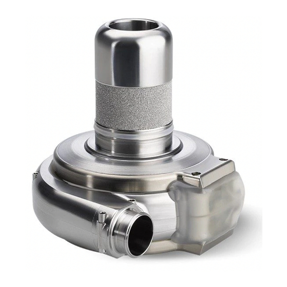
Pump is effi cient at pumping moderate quantities of blood against moderate amounts of resistance. 3.5 Device Tracking and Reporting Requirements .....63 Figure 33: Open View of HVAD Pump ® Infl ow Cannula Impeller Center Post HeartWare™ HVAD™ System Pump... - Page 62 (electrical current, impeller speed) and blood viscosity. Viscosity is calculated from the patient’s hematocrit. To obtain the most accurate estimate of blood flow, the patient’s hematocrit must be entered into the HeartWare Monitor. Flow estimation should be used as a trending tool ®...
-
Page 63: Physiologic Control Algorithms
Controller Display of less than 2.0 L/min, or greater than 10.0 L/min may indicate an electrical fault, incorrect hematocrit entry or an occlusion and/or thrombus or other materials (e.g. tissue fragments) in the device. Inaccurate assessment of HVAD Pump flow may lead to less than optimal ® treatment. HeartWare™ HVAD™ System Pump... -
Page 64: Ventricular Suction Detection] Alarm
3.2 Physiologic Control Algorithms (continued) 3.2.2 [Ventricular Suction Detection] Alarm A suction condition may occur due to ventricular collapse or inflow occlusion. Ventricular collapse occurs when a continuous flow VAD attempts to pump more blood from the left ventricle than is available, resulting in considerable reduction in ventricular volume. Left ventricular collapse can be the result of clinical events affecting left ventricular preload, including hypovolemia (bleeding), right heart failure, arrhythmia or pulmonary embolus. - Page 65 CAUTION: Do NoT enable the [Ventricular Suction Detection] alarm while the patient is in a suction condition. To optimize operation of the suction detection the patient should be hemodynamically stable prior to enabling the [Ventricular Suction Detection] alarm. HeartWare™ HVAD™ System Pump...
- Page 66 3.2 Physiologic Control Algorithms (continued) 3.2.2 [Ventricular Suction Detection] Alarm (continued) The ventricular suction detection function will temporarily deactivate if: • The estimated flow value becomes invalid. once the flow estimation is within valid range, the ventricular suction detection will resume. •...
-
Page 67: Hvad ® Pump Operating Guidelines
US Food and Drug Administration (FDA) and other foreign regulatory agency regulations. Compliance is mandatory. Accordingly, all device tracking paperwork must be completed and promptly returned to HeartWare. In addition, any device malfunctions must be reported to HeartWare by the implanting center. - Page 68 Notes HVAD® Instructions for Use...
-
Page 69: Heartware™ Hvad™ System Peripherals And Accessories
• Never disconnect both power sources at the same time or the pump will stop for Use at Home ..84 CAUTION: ALWAYS keep all connectors free of liquid, dust and dirt, or the HeartWare HVAD System may not ™ ™... - Page 70 4.1 HVAD Controller Connections (continued) ® Driveline Connection to the Controller: To Disconnect the Driveline from the Controller: 1. Slide the driveline cover away from the controller so you can see the whole silver connector. Figure 36 2. Place your fi ngers on the silver connector, over the ringed area. Figure 37 3.
- Page 71 CAUTION: ALWAYS confirm that the power cables are properly locked on the controller by gently pulling the cable near the controller power connector or the power cables may come loose and result in an alarm or the pump stopping. HeartWare™ HVAD™ System Peripherals and Accessories...
- Page 72 4.1 HVAD Controller Connections (continued) ® Disconnecting Power Sources: Disconnecting from the AC Adapter or DC Adapter Before switching from AC or DC power to battery power, make sure that a fully charged battery is available. Connect the fully charged battery after disconnecting the AC or DC adapter.
-
Page 73: Hvad ® Controller
9. Implant Date 3. [High Power] alarm (Setting) 10. Controller Date 4. Hematocrit (Setting) 11. VAD ID 5. RPM Setting 12. Patient ID 6. Suction Response (On/Off) 13. Controller Software Version 7. Peak Flow (L/min) HeartWare™ HVAD™ System Peripherals and Accessories... - Page 74 4.2 HVAD Controller (continued) ® Table 24: Guide to Controller Display, Buttons, and Indicators The CoNTRoLLER DISPLAY gives pump information including impeller speed (RPM), power (Watts), and blood fl ow (L/min). When an alarm occurs, the pump information is replaced by two lines of text that tell you what the alarm is and what to do.
- Page 75 System components should not be used adjacent to or stacked with ™ ™ equipment other than specified in the IFU. If adjacent to or stacked use is necessary, the HeartWare ™ HVAD System and other equipment should be observed to verify normal operation.
- Page 76 WARNING! Do NoT drop the controller or other equipment. Dropping the controller could cause sudden stoppage of the pump. Dropped equipment should be reported to HeartWare and inspected. WARNING! Do NoT disconnect the driveline or power sources from the controller while cleaning it or the pump will stop.
-
Page 77: Using The Heartware ® Batteries
For additional information on using the HVAD Controller, see Section 4.1. ® Table 25: Battery Capacity Battery Capacity Battery Capacity Display 75-100% 4 GREEN lights 50-74% 3 GREEN lights 25-49% 2 GREEN lights less than 25% 1 GREEN light HeartWare™ HVAD™ System Peripherals and Accessories... - Page 78 4.3 Using the HeartWare Batteries (continued) ® The controller will provide 3 indications for when to change a battery: 1. Battery indicator will show 1 yellow light. 2. Alarm indicator will be solid yellow. 3. Display will read [Low Battery] [Replace Battery].
-
Page 79: 4.3 Using The Heartware
25% capacity and is providing disconnect both batteries at the primary power. same time. This will stop your pump. The controllers shown above are meant to be examples of the changes you might see during the day. HeartWare™ HVAD™ System Peripherals and Accessories... -
Page 80: 4.3 Using The Heartware
4.3 Using the HeartWare Batteries (continued) ® WARNING! ALWAYS keep a spare controller and fully-charged spare batteries available at all times in case of an emergency. HeartWare HVAD System Power Management Guide is available from your ™ ™ clinician. Care of Batteries 1. -
Page 81: 4.3 Using The Heartware
CAUTION: Do NoT expose batteries to temperatures outside the storage and operational ranges or they may provide less support than usual. To preserve battery life, batteries should be stored at room temperature. Battery operating and storage temperatures: a. Operating: discharge (normal use with the HeartWare HVAD System): 0°C to +50°C (+32°F to ™... -
Page 82: 4.3 Using The Heartware
Otherwise, dispose of all expired or damaged equipment according to applicable local, state, and federal laws and regulations. For additional product disposal support and information, contact HeartWare. HeartWare Li-Ion battery cells Do NoT contain lead. Dispose of/recycle HeartWare Batteries in ®... -
Page 83: Using The Heartware ® Battery Charger
2. Place the battery into the slot. For the best fi t, loop the cable gently to the side and place the battery with the cable-side down. Figure 54 3. Repeat steps 1 and 2 for all batteries. The charger can hold up to 4 batteries at one time. Figure 55 HeartWare™ HVAD™ System Peripherals and Accessories... -
Page 84: 4.4 Using The Heartware
Battery too cold or too hot; waiting to charge. Defective battery. Do NoT use. Flashing Red Mark battery and return to Clinician. CAUTION: oNLY use the HeartWare Battery Charger to charge HeartWare Batteries. Other battery ® ® chargers will not charge the batteries and may damage them. -
Page 85: 4.4 Using The Heartware
• Inspect the battery charger for signs of physical damage, such as dents, chips, or cracks. Do NoT use the charger if it shows signs of damage. Contact HeartWare for a replacement. • Inspect the power cord used to connect the charger to an electrical outlet. Make sure the cord is not kinked, split, cut, cracked, or frayed. -
Page 86: Using The Hvad ® Controller Ac Adapter Or Dc Adapter
4.5 Using the HVAD Controller AC Adapter or DC Adapter ® (Figure 57) The AC adapter has cables that connect to the controller and into an electrical outlet. Prior to connection to the controller, verify proper connection of the power cord to the (Figure 58) adapter and electrical outlet. -
Page 87: Carrying Cases
WARNING! Do NoT plug the controller into an AC wall outlet during showers; to eliminate the possibility of a severe electrical shock, it should be connected to two batteries. WARNING! Do NoT allow patients to take a bath or swim, as this may damage HeartWare HVAD ™... -
Page 88: Recommended Equipment For Use At Home
Pump. Doing so could cause harm to the patient or could cause the pump to stop. ® WARNING! Do NoT apply high power electrical treatment (e.g., deep tissue heating which can be used for treatment of arthritis and/or some injuries) directly to the patient, as this may affect HeartWare ™ HVAD System operation. -
Page 89: Using The Heartware® Monitor
CAUTION: ALWAYS fully charge the monitor’s internal battery prior to patient use. 5.6 Monitor Shutdown ...105 CAUTION: Do NoT allow patients to touch the monitor, as this may lead to the entering of unwanted HeartWare ™ HVAD System parameters. ™... - Page 90 5.1 General Overview (continued) The monitor is designed to provide a user-friendly way to monitor and control the HeartWare ™ HVAD System. The monitor: ™ • Displays pump information • Allows users to adjust pump parameters • Monitors and reports system errors and alarm conditions •...
-
Page 91: Informational Screens
5.2 Informational Screens Examples of the Clinical (home), Alarm and Trend screens are below: Figure 63: Clinical Screen For additional information on setting speed and flow waveform (pulsatility), see Section 7.1.1. Figure 64: Alarm Log Using the HeartWare® Monitor... - Page 92 5.2 Informational Screens (continued) Figure 65: Troubleshooting Tab For additional information on alarms, see Section 8.1. Figure 66: Trend Screen Trend data is uploaded from the controller to the monitor by connecting the monitor data cable to the controller. For additional information on downloading controller log fi les, see Section 5.4. HVAD®...
-
Page 93: System Screens
Pump Icon. ® Figure 67: Password Dialog Box The System Screen is password-protected. HeartWare will provide (Figure 67) the clinician with a password. The dialog box is used to enter the numeric password. User access is timed out after 11 minutes of non-use. (password is 68773) Once in the System Screen there are multiple pages, each identifi ed by a tab. - Page 94 5.3 System Screens (continued) Speed/Control Tab (continued) Confirm the speed adjustment by pressing the “Change” button. The HVAD Pump button is ® colored and labeled according to the running state of the HVAD Pump: ® • VAD: oN means the HVAD Pump is pumping;...
- Page 95 70). This The hematocrit can be changed using the “Hematocrit (%)” button method allows the clinician to manually input the patient’s hematocrit using a measurement obtained from a blood sample. The default hematocrit value is 30%. Using the HeartWare® Monitor...
- Page 96 5.3 System Screens (continued) VAD Tab (Figure 73) The VAD tab is used to enable or disable the Suction Response and to enter the HVAD Pump serial number. ® Figure 73: VAD Tab Logout Patient Controller Monitor Controller L/min HW1400 VAD ID: 2860 Fixed...
- Page 97 For additional information on suction detection, see Section 3.2.2. When the pump speed is changed by accessing the Speed/Control tab, the dialog box reminds (Figure 75). users that this will disable the suction detection alarm Figure 75: Dialog Box for Pump Speed Changes Using the HeartWare® Monitor...
- Page 98 5.3 System Screens (continued) Controller Tab (Figure 76) The Controller tab allows the user to enter the controller date, time and language and activate the ‘Disable “VAD Stop” Alarm’ feature. Monitor REF1510 also allows the user to set the controller default values. Figure 76: Controller Tab Logout...
- Page 99 6. Disable [No Power] alarm by pressing the “Alarm Mute” and “Scroll” buttons simultaneously for 5 seconds. 7. Disconnect power from controller. 8. The [VAD Stop] alarm will be re-armed automatically after 3 minutes as long as the monitor (Figure 79). is not connected to a controller Using the HeartWare® Monitor...
- Page 100 5.3 System Screens (continued) Disable “VAD Stop” Alarm (continued) Figure 78: Disable “VAD Stop” Alarm Logout ---- Patient Controller Monitor Controller L/min Controller ---- Date: ---- Controller ---- Time: ---- Controller ---- Language: Watts Disable “VAD Stop” Alarm Time (s) Speed/ Alarm Setup...
- Page 101 • The [Low Flow] alarm should be set at 2.0 L/min below the patient’s average flow. Do NoT set the [Low Flow] alarm below 2.0 L/min. • The [High Power] alarm should be set 2.0 Watts above the patient’s average power. Using the HeartWare® Monitor...
- Page 102 5.3 System Screens (continued) Alarm Settings Tab (continued) Figure 82: Alarm Settings Tab When certain alarm or fault conditions exist, the Alarm Settings tab may be used to access additional controls to silence the audio component of the alarm or fault for extended time periods.
- Page 103 Control Control Settings HW1234567 POD: 0 00:01:31 For additional information on alarms, see Section 8.1. WARNING! ALWAYS investigate, and if possible, correct the cause of any alarm. Silencing an alarm does not resolve the alarm condition. Using the HeartWare® Monitor...
-
Page 104: Downloading Controller Log Files
5.3 System Screens (continued) Alarm Settings Tab (continued) The user should always log off the password-protected System Screens after completing system adjustments. Press the “Logout” button and confi rm by pressing the “Yes” button to return to the Clinical Screen. If the System Screen is not used for 11 minutes, the user is automatically logged out and needs to enter the password to access these screens. -
Page 105: Updating Software On The Hvad ® Controller
When a new version of controller software is available for installation a notification from HeartWare will be sent describing the update. If needed, a HeartWare representative will update the monitor software and confirm the monitor is able to perform the controller software update. - Page 106 5.5 Updating Software on the HVAD Controller (continued) ® 2. Press the HeartWare HVAD System Icon on the monitor and enter password: 68773 ™ ™ 3. Disable “VAD Stop” alarm to prevent alarming (Figure 91) a. Press Setup tab b. Press Controller tab c.
- Page 107 Confirm that the replacement software version displayed is the desired controller software version. The desired software version should be the one listed on the latest controller software update notification received from HeartWare. b. Press “Replace Software”. c. Press “Yes” to confirm.
- Page 108 7 (even if the alarm continues to sound). If after repeating the update procedure a high or medium priority alarm returns, remove the controller from use and contact your HeartWare representative. If the controller belongs to a patient, provide a replacement controller.
-
Page 109: Monitor Shutdown
If the monitor battery fails to hold a charge, or lasts less than one hour, please contact HeartWare for a replacement. Also, check the monitor AC adapter and power cord for wear or damage and confirm they are working correctly. Turn off the monitor prior to cleaning. - Page 110 5.7 HeartWare Monitor Care (continued) ® WARNING! NEVER clean the monitor with the power on, as this may lead to an electrical shock. Do NoT use alcohol or detergent on the monitor display. Gently wipe the display with a soft, lint free cloth.
-
Page 111: Surgical Implant And Explant Of The Hvad ® Pump
6.0 Surgical Implant and Explant of the HVAD Pump ® 6.1 Preparing for Implantation 6.1 Preparing for Implantation ....107 Equipment for Implant Figure 97 shows the HeartWare HVAD System ™ ™ components used at implant (provided ETO sterilized). 6.2 Programming HVAD ® Controllers ....109... - Page 112 All tools and accessories used during implantation are for single-use only. CAUTION: Do NoT use HeartWare equipment in the presence of a fl ammable anesthetic mixture with air or with oxygen or nitrous oxide. (NoTE: Flammable anesthetics are typically ether based).
-
Page 113: Programming Hvad ® Controllers
Battery Charger 1. Connect the battery charger power cable to an electrical outlet. Verify the power indicator is lit next to “HeartWare”. 2. Verify availability of four fully charged batteries. If batteries are not fully charged, start charging depleted batteries at least 5 hours before the HVAD Pump implant procedure. - Page 114 6.2 Programming HVAD Controllers (continued) ® 10. Remove data cable. 11. To prevent the controller alarm from sounding after the power is removed, follow these instructions: • If a red alarm adapter is available: Insert it into the connector on the controller. •...
-
Page 115: Hvad ® Pump Pre-Implant Test And Pump Assembly
6.2 Programming HVAD Controllers (continued) ® 13. Place the controller in the carrying case and position the case close to the head of the OR table so the driveline can be connected to the controller after tunneling. WARNING! Keep power connected to the controller after setting up the primary controller to minimize the risk of air embolus during implant. - Page 116 6.3 HVAD Pump Pre-Implant Test and Pump Assembly (continued) ® 7. on the sterile fi eld, fi ll a basin with enough 5% dextrose solution to establish at least 4.0 inches (10.2 centimeters) of fl uid above the pump infl ow (Figure 100).
- Page 117 6.3 HVAD Pump Pre-Implant Test and Pump Assembly (continued) ® 16. Run the HVAD Pump for 30 – 60 seconds. As part of the normal HVAD Pump startup ® ® algorithm, the monitor and controller may momentarily display power values greater than 3.0 Watts before settling at a lower power.
- Page 118 6.3 HVAD Pump Pre-Implant Test and Pump Assembly (continued) ® Outfl ow Graft Attachment (continued) WARNING! Do NoT allow anyone but a surgeon, physician’s assistant or surgical assistant trained in the procedure to attach the outfl ow graft to the pump, as a loose graft connection may lead to bleeding and/or an air embolus.
-
Page 119: Surgical Implant Procedure
Pump outflow graft with a vascular clamp, then wrap it all in a clean ® towel. 6.4 Surgical Implant Procedure NOTE: In order to optimize patient outcomes HeartWare suggests that the following techniques be considered at the time of HVAD Pump implant: ®... - Page 120 6.4 Surgical Implant Procedure (continued) Pump Implantation Preparation 1. Make a standard median sternotomy incision. 2. Open the pericardium to expose and access the left ventricle (LV) apex. 3. Consider a transesophageal echocardiography (TEE) prior to placing the patient on cardiopulmonary bypass to assess for a patent foramen ovale (PFO).
- Page 121 6.4 Surgical Implant Procedure (continued) Left Ventricle (LV) Apex Cannulation (continued) NOTE: The sewing ring is packaged at the optimal open diameter to allow for insertion of the inflow cannula. If you make any adjustments, check to be sure the inflow cannula passes easily through the sewing ring.
- Page 122 6.4 Surgical Implant Procedure (continued) Outflow Graft Anastomosis 1. Gently stretch the outflow graft, measure and cut to length. The outflow graft should lie without kinking or overstretching. 2. Place a partial occlusion clamp on the portion of the ascending aorta where the outflow graft will be placed.
- Page 123 6.4 Surgical Implant Procedure (continued) Driveline Placement (continued) Figure 110: Driveline cap attachment to tunneler CAUTION: The driveline connector is made of nickel- coated brass which may cause a rash in patients with a nickel allergy. CAUTION: ALWAYS be aware of the position of the Driveline driveline to avoid damage by surgical instruments and (under skin)
- Page 124 6.4 Surgical Implant Procedure (continued) De-airing Procedure (continued) CAUTION: ALWAYS use the smallest possible needle for de-airing; 19-gauge is normally sufficient. Hypodermic needles have a cutting point which may result in blood leakage and may require repair by suturing. 5. Start HVAD Pump at 1800 RPM by pressing the blue button labeled “START”...
-
Page 125: Hvad ® Pump Explant
Pump in 5% Formaldehyde for at least 2 days. ® 15. Allow the HVAD Pump to thoroughly dry. ® 16. Follow the packaging instructions provided in the Explant Kit (provided by HeartWare) and return the HVAD Pump in the Explant Kit. ® HeartWare, Inc. - Page 126 Notes HVAD® Instructions for Use...
-
Page 127: Patient Management And Education
7.0 Patient Management and Education 7.1 Postoperative Management 7.1 Postoperative After implantation, the patient is returned to the intensive Management ....123 care unit. Fluids are given to maintain pump flow index (pump flow ÷ BSA) at greater than 2.0 L/min/m with 7.1.1 Setting Speed with HVAD ®... -
Page 128: Setting Speed With Hvad ® Pump
Pump fl ow pulsatility is the ® difference between the minimum (trough) and maximum fl ows which are displayed in the fl ow waveform on the HeartWare Monitor. Pulsatility is refl ected in a positive waveform (similar in ® form to an arterial line waveform) where the trough value represents the fl ow during left... -
Page 129: Blood Pressure Maintenance
7.1 Postoperative Management (continued) 7.1.2 Blood Pressure Maintenance Managing blood pressure post continuous flow VAD implant is described in the ISHLT Guidelines. Similar to the ISHLT Recommendations, monitoring of blood pressure following HVAD implant has shown to be very important to optimize patient results, in particular to minimize risk of stroke. Since the HVAD Pump provides continuous flow resulting in narrow arterial systolic/diastolic ®... -
Page 130: Right Heart Failure
7.1 Postoperative Management (continued) 7.1.4 Right Heart Failure Right heart failure is common in patients receiving LVADs. Right heart failure usually develops within the first 24 hours after LVAD implant. Warning signs include increasing right atrial pressure (RAP) with concurrent decreases in the pulmonary capillary wedge pressure (PCWP) and LVAD flow. -
Page 131: Driveline Care
Experience: Prevention and Management of Left Ventricular Assist Device Infections”. Chinn et al. ASAIo Journal 2005; 51:461–470 CAUTION: ALWAYS examine the driveline for evidence of tears, punctures or breakdown of any of the material during exit site dressing changes. Driveline damage may affect HeartWare HVAD System ™... -
Page 132: Emergency Management
7.3 Emergency Management In the event of an emergency, such as a cardiac arrest, patients with the HeartWare HVAD ™ ™ System may be defibrillated with either an internal or external defibrillator. The HeartWare HVAD ™ ™ System can be left on, nothing needs to be turned off or disconnected. If chest compressions are performed, confirm function and positioning of HVAD Pump once the patient is stable. -
Page 133: Heartware Hvad System Alarms And Emergencies
5 silenced for the “Mute” min or 1 hour 5 min button • Controller Controller • The alarm will and Electrical Silencing clear once Faults the problem may be is resolved permanently silenced HeartWare™ HVAD™ System Alarms and Emergencies... -
Page 134: High Priority Alarms
8.1 Alarm Overview (continued) When an alarm occurs, two lines of text appear in the Controller Display. The first line describes the alarm and the second line tells you what to do. See example below: Figure 113: Alarm text display 1st line tells you what the alarm is Low Battery 1... - Page 135 • the other battery is replaced with another charged battery (≥ 25%) or power adapter. (Note: if the other battery is changed to a valid power source, but the non-communicating battery is still connected, the alarm will change to a [Power Disconnect], low priority alarm.) HeartWare™ HVAD™ System Alarms and Emergencies...
-
Page 136: Medium Priority Alarms
HVAD Pump will be running on a single stator and will consume ® slightly more power. Do not change controllers during an active [Electrical Fault] alarm. Download controller log files and send to HeartWare for review. HVAD® Instructions for Use... - Page 137 Download the controller log files at the patient’s next clinic visit and send to HeartWare for analysis. • Instruct the patient to return to the center as soon as reasonable (not emergently) so the...
-
Page 138: Low Priority Alarms
– Download the log files from the original controller and the current controller and send them to HeartWare for analysis. The [Controller Fault] alarm audio can be permanently silenced but this cannot be done by the patient. -
Page 139: Multiple Alarms
An (Figure 114). Use the “Scroll” arrow is displayed on the right side of the alarm for multiple alarms button to see all active alarms. Controller displaying multiple alarms Figure 114: HeartWare™ HVAD™ System Alarms and Emergencies... -
Page 140: How To Silence (Mute) Alarms
8.5 Multiple Alarms (continued) Table 32: Multiple Alarms Multiple Alarm Alarm Indicator Alarm Sound Condition Loud, continuous, Flashing RED More than 2 High Alarms unable to mute Loud, continuous, Flashing RED High and Medium Alarms unable to mute Loud, continuous, High and Low Alarms Flashing RED unable to mute... -
Page 141: How To Change The Controller
A controller failure or serious controller malfunction will generate a high priority or RED alarm and the Controller Display will tell you if you should “Change Controller”. HeartWare™ HVAD™ System Alarms and Emergencies... - Page 142 8.7 How to Change the Controller (continued) Steps to Change the Controller: 1. Have patient sit or lie down and place the new controller within easy reach. Figure 115 2. Connect one POWER source to the new controller. NoTE: The new controller may alarm after 10 seconds with a [VAD Stopped, Connect Driveline] high alarm.
- Page 143 Figure 122 7. Remove the original controller from service and provide a new back-up controller to the patient. HeartWare™ HVAD™ System Alarms and Emergencies...
- Page 144 8.7 How to Change the Controller (continued) When doing a controller exchange, the priority is to restart the pump quickly. It may be helpful to remember the 4 P’s: 1. POWER... Connect a power source to your back up controller. 2.
-
Page 145: Quick Reference Guide For Alarms
• No power to pump • Connect two new power sources loud message) message) • Pump has stopped • Replace controller • Unable to • Contact HeartWare Clinical Support mute Flashing [VAD [Connect • Loud, • Driveline disconnected • Reconnect driveline... - Page 146 • Download/email patient log • [High Power] alarm may files from original (alarming) be disabled controller and new controller • Contact HeartWare Clinical Support [High [Call] • HVAD Pump Watts have • Confirm correct settings for ®...
- Page 147 • Connector malfunction • Download/email patient log • Able to mute alarm files • Controller component for 5 minutes or failure • Contact HeartWare Clinical 1 hour Support • VAD malfunction • Electrical Fault (audio) and [Low Flow] [Call] •...
- Page 148 Notes HVAD® Instructions for Use...
-
Page 149: Appendix
10.0 Appendix Appendix A: System Components Appendix A: Implantables (Supplied Sterile - ETO) System Components ..145 • HVAD Pump ® • 10mm gel impregnated polyester graft • Sewing Ring Appendix B: • Strain Relief Product Specifications ..146 Surgical Tools and Accessories (Supplied Sterile - ETO) •... -
Page 150: Appendix B Product Specifications
Appendix B: Product Specifications Essential Performance The HVAD Pump runs with adequate flow ® Pump Mass (or weight) 160 g Volume 50 cc Materials Titanium, Titanium Nitride, PEEK and ceramic ® Outflow Graft Gel impregnated polyester graft Length 60 cm Diameter (or size) 10 mm Materials... - Page 151 Appendix B: Product Specifications (continued) Monitor REF1510 REF1520 Type Notebook with touch screen Input Operating System Weight 2.5 kg 3.0 kg 28.5 x 21.0 x 4.1 cm (without case) Dimensions 29.9 x 23.5 x 4.5 cm 29.9 x 29.9 x 6.4 cm (with case) Electrical Ratings 19 V, 3 A maximum input 19 V, 3.4 A maximum input...
-
Page 152: Appendix C Emc Manual Requirements Guidance Document
500 -1060 hPa -40 to +70°C (-40 to +158°F) Do not store HeartWare equipment in an area exposed to ultraviolet light. The box label details conditions for transport and storage. The device label details the environmental condition limits under which the device should be operated. - Page 153 Appendix C: EMC Manual Requirements Guidance Document (continued) Guidance and Manufacturer’s Declaration - Electromagnetic Immunity The HVAD Pump is indicated for use in the electromagnetic environments specified below. The customer ® or the user of the HVAD Pump should assure it is used in such an environment. ®...
- Page 154 Appendix C: EMC Manual Requirements Guidance Document (continued) Guidance and Manufacturer’s Declaration - Electromagnetic Immunity (continued) Immunity IEC 60601 Compliance Test Test Level Level Guidance Portable and mobile RF communications equipment should be used no closer to any part of the HVAD Pump, including cables, ®...
- Page 155 Appendix C: EMC Manual Requirements Guidance Document (continued) The ISM (industrial, scientific and medical) bands between 150 kHz and 80 MHz are 6.765 MHz to 6.795 MHz; 13.553 MHz to 13.567 MHz; 26.957 MHz to 27.283 MHz; and 40.66 MHz to 40.70 MHz. The compliance levels in the ISM frequency bands between 150 kHz and 80 MHz and in the frequency range 80 MHz to 2.5 GHz are intended to decrease the likelihood that mobile/portable communications equipment could cause interference if it is inadvertently brought into patient areas.
-
Page 156: Appendix D Symbol Definitions
Appendix D: Symbol Definitions Attention, consult Not made with natural Manufacturer LATEX accompanying documents rubber latex Sterilized with ethylene oxide Follow operating Instructions Prescription only symbol Batch code Non sterile UL Classifi cation Mark General medical equipment as to electrical shock, fi re and mechanical hazards only in Catalog number Single use only, do not reuse... - Page 158 24-Hour Clinical Support: Toll free (888) 494-6365 or (888) HW INFo 5 HeartWare, Inc. 14400 NW 60th Avenue Miami Lakes, FL 33014 USA www.heartware.com © 2017 HeartWare, Inc. HEARTWARE, HVAD, and the HEARTWARE logo are trademarks of HeartWare, Inc. IFU00375 Rev03 09/17...
Need help?
Do you have a question about the HVAD Pump and is the answer not in the manual?
Questions and answers