
Related Manuals for typical GC0303D


Summary of Contents for typical GC0303D
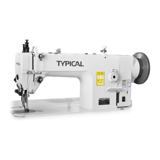
- Page 1 GC0303D DIRECT-DRIVE AUTO-LUBRICATION UPPER & LOWER FEED LOCKSTITCH SEWING MACHINE GC0303DCX DIRECT-DRIVE AUTO-LUBRICATION UPPER & LOWER FEED LOCKSTITCH SEWING MACHINE WITH THICK THREAD OPERATION INSTRUCTION / PARTS MANUAL...
- Page 2 Please don't adjust and repair the machine by non-professionals,except adjusting stitch. Specifications subject to change without notice TYPICAL SEWING MACHINE WANPING MACHINERY CO.,LTD. ADD: WANPING TOWN, WUJIANG CITY, JIANGSU 2012.4 PROVINCE, CHINA TEL: +86-512-63391278 FAX: +86-512-63391371 POST. CODE: 215223 Http://www.typicalwpchina.com...
-
Page 3: Table Of Contents
CONTENTS Operation Instruction 1、 Brief introduction …………………………………………………………………………………………………………1 2、 Machine specification ……………………………………………………………………………………………………1 3、 Installing the oil pan and safety switch magnet ………………………………………………………………………1 4、 Installing the machine head ………………………………………………………………………………………………2 5、 Installing the knee lifter assy. ……………………………………………………………………………………………2 6、 Adjusting the knee lifter …………………………………………………………………………………………………3 7、... -
Page 4: Operation Instruction
Operation Instruction... -
Page 5: Brief Introduction
It's suitable for sewing leather, canvas and other heavy weight materials, such as suitcase, car seat, tent, sofa, etc. 2. Main specifications Model GC0303D GC0303DCX Medium & heavy weight materials Applications 2000 s.p.m 1800 s.p.m... -
Page 6: Installing The Machine Head
4. Installing the machine head (Fig.2) 1.Insert the knee lifter lifting bar ①. 2.Insert the two hinges ② into the holes in the machine bed. 3.Clamp the two hinges onto the rubber cushions ③ in the work table, and the place the machine head onto the head cushions ④... -
Page 7: Adjusting The Knee Lifter
6. Adjusting knee lifter(Fig.4) 1.Lower the presser foot ② by turning the presser foot bar lifter ①. 2.Loosen the nut ③. 3.Turn the screw ⑥ to adjust the bracket ⑤ to 2mm play. 4.Securely tighten the nut ③. 5.Loosen the nut ⑦. 6.Turn the screw ⑧... -
Page 8: Test Operation
8. Test operation(Fig.6) Carry out the test operation when start up a new sewing machine for the first time, or restart after a long period of non-use. Remove the rubber cap (A) on the top of the arm and face plate, fully lubricate the parts showed by the arrows. -
Page 9: Installing The Needle
9. Installing the needle (Fig.7) 1.Turn the machine pulley to move the needle bar ① to its highest position; 2.Loosen the screw ② Groove leftward 3.Insert the needle ③ in a straight line as far as it will go, making sure that the long groove on the needle is at the left, and then securely tighten the screw ②... -
Page 10: Threading The Bobbin Thread
12. Threading the bobbin thread (Fig.10) 1.Turn the machine pulley to lift the needle to its highest position; 2.The bobbin thread should be right twist, place the bobbin into the bobbin case; 3.Pass the thread through the slot ① and spring plate ②, and finally pull it out of the notch ③;... -
Page 11: Adjusting The Stitch Length
14. Adjusting the stitch length (Fig.12) While press the stopper ②, turn the stitch length dial ① to make the number on the dial align with the mark on the stopper ②. The number is the stitch length in mm. *The larger the number, the longer the stitch length will be. -
Page 12: Adjusting The Thread Tension
16. Adjusting the thread tension (Fig.14) Normal stitch Needle thread Bobbin thread ●increase the needle thread tension ●Stitch seam when needle thread tension is too weak ●decrease the bobbin thread tension ●decrease the needle thread tension ●Stitch seam when needle thread tension is too strong ●increase the bobbin thread tension <Bobbin thread tension>... -
Page 13: Adjusting The Thread Tension Spring
18. Adjusting the thread tension spring (Fig. 16) ★The standard position of the thread tension spring ① is 5-8mm above the upper surface of the thread guide ③ when the presser foot ② is lowered. 5 ~ 8mm 1.Lower the presser foot ②; 2.Loosen the screw ④;... -
Page 14: Adjusting The Upper Thread Guide
19. Adjusting the upper thread guide (Fig. 17) Increase Decrease The standard position of upper thread guide ① is where the screw ② is in the center of the adjustable range of upper thread guide. To adjust the position, loosen the screw ② and move the thread guide. -
Page 15: Adjusting The Feed Dog Angle
22. Adjusting the feed dog angle (Fig. 20) Mark The standard angle of the feed dog is: when the feed dog is at its highest position above the needle plate, the Mark on the feed bracket shaft is on the horizontal position. 1.Turn the machine pulley to lift the feed dog to its highest position;... -
Page 16: Adjusting The Timing Of Needle And Feed Mechanism
25. Adjusting the timing of needle and feed mechanism (Fig. 23) The standard timing is when the feed dog is lowered from its highest position until it is flush with the top of the needle plate ②, and the needle eye ③ is also aligned horizontally with the surface. -
Page 17: Adjusting The Height Of Needle Bar And The Timing With Hook
27. Adjusting the height of needle bar and the timing with hook (Fig. 25) When the needle bar ① is at its lowest position, the top reference line (A) on the needle bar should be aligned with the bottom edge of the needle bar bush ②. - Page 18 29. Adjusting the lifting amount of presser feet (Fig. 27) 1.Vertical movement of presser foot and walking foot Left Right ★The presser foot ① and walking foot ② move vertically one after another ★Usually the stroke of walking foot and presser Smaller foot is same or the stroke of walking foot is Larger...
- Page 19 30.Clean (Fig. 28) 1.Raise the presser foot; 2.Remove the two screws ① and needle plate ②; 3.Clean the feed dog with a soft brush; 4.Install the needle plate ② by two screws ①. 5.Turn the machine pulley slowly and check if the needle drops into the hole center of needle plate ★If not ●Check if the needle is bent...
-
Page 20: Parts Manual
Parts Manual... - Page 21 1. Casting mechanism 24-1 24-2 24-3 9-11 9-10 -16-...
- Page 22 1. Casting mechanism No . Part number Name Remark 0303D 0303DCX Face plate 1KT1-002 Screw 7WF4-004 Thread guide 22T1-003C5 Thread guide 22T1-014 Screw 22T1-003C6 Thread guide assy. 36T2-006D Thread guide 36T2-006D1 Pre-tension stud 36T2-006D2 Tension disc 22T2-009E3 Tension spring 2KT2-011 Adjusting screw 36T2-006D4 Set screw...
-
Page 23: Needle Bar And Thread Take-Up Mechanism Clean
2. Needle bar and thread take-up mechanism 31-1 31-2 -18-... - Page 24 2. Needle bar and thread take-up mechanism No . Part number Name Remark 0303D 0303DCX Upper shaft 271WF2-001 Robber cap 22T3-001A2 Collar 22T3-002B1 Screw 22T3-002B2 Bush, L 4WF1-006A Bush, M 4WF1-002 φ20xφ42x12 Set screw J0.0.40 Bearing, R Oil seal 258WF2-004 Hand wheel 273WF2-001 Screw...
-
Page 25: Presser Foot Mechanism
3. Presser foot mechanism -20-... - Page 26 3. Presser foot mechanism No . Part number Name Remark 0303D 0303DCX Presser bar lifter Screw 4WF3-002 Lifter crank O ring GB3452.1 4.5×1.8G Lifter lever Guide plate Screw Screw Collecting rod Screw Lever Spring, extension Knee lifter bar Spring hook Shoulder screw Bush 241WF5-001...
-
Page 27: Feed Mechanism
4. Feed mechanism -22-... - Page 28 4. Feed mechanism No . Part number Name Remark 0303D 0303DCX 20T3-008 Feed dog 75WF4-001 Feed dog 36T4-001A1a1 Feed bar 75WF4-005A Feed bar 51T5-001A6 Washer 36T4-001A2 Shaft J0.0.50 Screw 4WF2-002 Feed rock arm 61-04-01/B504 Screw 22T2-019 GB894.1 15 Screw 7WF2-004 Feed shaft Retaining ring 7WF2-002...
- Page 29 4. Feed mechanism -24-...
- Page 30 4. Feed mechanism No . Part number Name Remark 0303D 0303DCX Spring 22T5-009 Stopper pin 7WF2-006 36T3-003D Set screw Feed cam 36T5-008E Feed connecting rod 4WF2-009A Connecting rod 4WF2-009B Stud 82T2-003C1a10-1 Link 36T5-008E4H02 Set screw 36T5-008E5 Set screw 21WF1-060 36T5-008E4H01 Link 36T5-008E6 Shaft...
-
Page 31: Upper Feed Mechanism
5. Upper feed mechanism -26-... - Page 32 5. Upper feed mechanism No . Part number Name Remark 0303D 0303DCX 7WF5-001 Collar 7WF5-002 7WF5-003 Washer GB/T95 6 Roller shaft 7WF5-004 Roller 7WF5-005 Walking foot 7WF5-006 11WF5-001 Walking foot Screw 61-04-01/B316 Screw 7WF5-008 Washer GB93 4 Clamper 7WF5-009 Link 7WF5-010 7WF5-011 Shoulder screw...
-
Page 33: Hook Mechanism
6. Hook mechanism -28-... - Page 34 6. Hook mechanism No . Part number Name Remark 0303D 0303DCX Vertical shaft 15WF1-001 Bevel gear, upper shaft ZOA140379 Set screw 22T2-005B3 Bevel gear, vertical shaft, U ZOA140380 Bevel gear, lower shaft ZOA140383 Bevel gear, vertical shaft, L ZOA140382 Bush, vertical shaft, U 2KT1-015 Bush, vertical shaft, L 2KT1-008...
-
Page 35: Lubrication Mechanism
7. Lubrication mechanism -30-... - Page 36 7. Lubrication mechanism No . Part number Name Remark Pump body 1 5 W F 4 - 0 0 3 Big gear, pump 1 5 W F 4 - 0 0 6 Small gear, pump 1 5 W F 4 - 0 0 7 GB/T67 M3×10 Screw Cover...
-
Page 37: Accessories
8. Accessories 32 33 36 37 -32-... - Page 38 8. Accessories No . Name Remark Part number 0303D 0303DCX Accessory bag 3 3 T F - 0 1 0 Screw driver, S 3 3 T F - 0 1 4 Screw driver, M 3 3 T F - 0 1 3 Screw driver, L 3 3 T F - 0 1 2 DPX17 23#...
Need help?
Do you have a question about the GC0303D and is the answer not in the manual?
Questions and answers