Table of Contents
Advertisement
Advertisement
Table of Contents

Related Manuals for Innova 31403


Summary of Contents for Innova 31403
-
Page 2: Table Of Contents
Table of Contents INTRODUCTION WHAT IS OBD? ............................. YOU CAN DO IT! ................................. SAFETY PRECAUTIONS SAFETY FIRST! ............................. ABOUT THE SCAN TOOL VEHICLES COVERED ..........................BATTERY REPLACEMENT .......................... SCAN TOOL CONTROLS CONTROLS AND INDICATORS ........................DISPLAY FUNCTIONS ..........................ONBOARD DIAGNOSTICS COMPUTER ENGINE CONTROLS ....................... -
Page 3: Introduction
Introduction WHAT IS OBD? WHAT IS OBD? The Scan Tool is designed to work on all OBD2 compliant vehicles. All 1996 and newer vehicles (cars, light trucks and SUVs) sold in the United States are OBD2 compliant. One of the most exciting improvements in the automobile industry was the addition of on- board diagnostics (OBD) on vehicles, or in more basic terms, the computer that activates the... -
Page 4: You Can Do It
You Can Do It! EASY TO USE - EASY TO VIEW - EASY TO DEFINE Easy To Use ..Connect the Scan Tool to the vehicle’s test connector. Turn the ignition key "On.” The Scan Tool will automatically link to the vehicle’s computer. -
Page 5: Safety Precautions
Safety Precautions SAFETY FIRST! SAFETY FIRST! To avoid personal injury, instrument damage and/or damage to your vehicle; do not use the Scan Tool before reading this manual. This manual describes common test procedures used by experienced service technicians. Many test procedures require precautions to avoid accidents that can result in personal injury, and/or damage to your vehicle or test equipment. - Page 6 Safety Precautions SAFETY FIRST! To prevent damage to the on-board computer when taking vehicle electrical measurements, always use a digital multimeter with at least 10 MegOhms of impedance. Fuel and battery vapors are highly flammable. To prevent an explosion, keep all sparks, heated items and open flames away from the battery and fuel / fuel vapors.
-
Page 7: About The Scan Tool
About the Scan Tool VEHICLES COVERED VEHICLES COVERED The Scan Tool is designed to work on all OBD2 compliant vehicles. All 1996 and newer vehicles (cars and light trucks) sold in the United States are OBD2 compliant. Federal law requires that all 1996 and newer cars and light trucks sold in the United States must be OBD2 compliant;... -
Page 8: Battery Replacement
About the Scan Tool BATTERY REPLACEMENT On some Asian and European vehicles the DLC is located behind the “ashtray” (the ashtray must be removed to access it) or on the far left corner of the dash. If the DLC cannot be located, consult the vehicle’s service manual for the location. -
Page 9: Scan Tool Controls
Scan Tool Controls CONTROLS AND INDICATORS CONTROLS AND INDICATORS HONDA Figure 1. Controls and Indicators See Figure 1 for the locations of items 1 through 18, below. ERASE button - Erases Diagnostic Trouble Codes (DTCs), and “Freeze Frame” data from your vehicle’s computer, and resets Monitor status. - Page 10 Scan Tool Controls DISPLAY FUNCTIONS DOWN button - When in MENU mode, scrolls DOWN through the menu and submenu selection options. When LINKED to a vehicle, scrolls DOWN through the current display screen to display any additional data. UP button - When in MENU mode, scrolls UP through the menu and submenu selection options.
-
Page 11: Display Functions
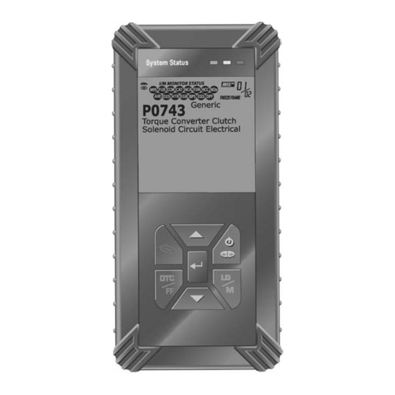
Scan Tool Controls DISPLAY FUNCTIONS DISPLAY FUNCTIONS 11 12 13 Figure 2. Display Functions See Figure 2 for the locations of items 1 through 14, following. 1. I/M MONITOR STATUS field - Identifies the I/M Monitor status area. 2. Monitor icons - Indicate which Monitors are supported by the vehicle under test, and whether or not the associated Monitor has run its diagnostic testing (Monitor status). - Page 12 Scan Tool Controls DISPLAY FUNCTIONS batteries need replacement. No data will be displayed on screen when all 3 LEDs are lit. 7. DTC Display Area - Displays the Diagnostic Trouble Code (DTC) number. Each fault is assigned a code number that is specific to that fault.
-
Page 13: Onboard Diagnostics
Onboard Diagnostics COMPUTER ENGINE CONTROLS COMPUTER ENGINE CONTROLS The Introduction of Electronic Engine Controls Electronic Computer Control Systems make it possible for vehicle manufacturers to comply with the tougher emissions and fuel efficiency standards mandated by State and Federal Governments. As a result of increased air pollution (smog) in large cities, such as Los Angeles, the California Air Resources Board (CARB) and the Environmental Protection Agency (EPA) - Page 14 Onboard Diagnostics COMPUTER ENGINE CONTROLS The Basic Engine Computer Control System The Computer Control System consists of an on-board computer and several related control devices (sensors, switches, and actuators). The on-board computer is the heart of the Computer Control System. The computer contains several programs with preset reference values for air/fuel ratio, spark or ignition timing, injector pulse width, engine speed, etc.
- Page 15 Onboard Diagnostics COMPUTER ENGINE CONTROLS Vehicle operating conditions are constantly changing. The computer continuously makes adjustments or corrections (especially to the air/fuel mixture and spark timing) to keep all the engine systems operating within the preset reference values. On-Board Diagnostics - First Generation (OBD1) With the exception of some 1994 and 1995 vehicles, most vehicles from 1982 to 1995 are equipped with some type of first generation On-Board Diagnostics.
- Page 16 Onboard Diagnostics COMPUTER ENGINE CONTROLS Because OBD1 systems only detect failed components, the degraded components were not setting codes. Some emissions problems related to degraded components only occur when the vehicle is being driven under a load. The emission checks being conducted at the time were not performed under simulated driving conditions.
- Page 17 Onboard Diagnostics COMPUTER ENGINE CONTROLS Powertrain Control Module (PCM) - The PCM is the OBD2 accepted term for the vehicle’s “on-board computer.” In addition to controlling the engine management and emissions systems, also participates in controlling the powertrain (transmission) operation. Most PCMs also have the ability to communicate with other computers on the vehicle (ABS, ride control, body, etc.).
-
Page 18: Diagnostic Trouble Codes (Dtcs)
Onboard Diagnostics DIAGNOSTIC TROUBLE CODES (DTCs) OBD2 Drive Cycle - An OBD2 Drive Cycle is an extended set of driving procedures that takes into consideration the various types of driving conditions encountered in real life. These conditions may include starting the vehicle when it is cold, driving the vehicle at a steady speed (cruising), accelerating, etc. - Page 19 Onboard Diagnostics DIAGNOSTIC TROUBLE CODES (DTCs) Manufacturer-Specific DTCs are codes that are controlled by the vehicle manufacturers. The Federal Government does not require vehicle manufacturers to go beyond the standardized generic DTCs in order to comply with the new OBD2 emissions standards.
- Page 20 Onboard Diagnostics DIAGNOSTIC TROUBLE CODES (DTCs) DTCs and MIL Status When the vehicle’s on-board computer detects a failure in an emissions-related component or system, the computer’s internal diagnostic program assigns a diagnostic trouble code (DTC) that points to the system (and subsystem) where the fault was found.
-
Page 21: Obd2 Monitors
Onboard Diagnostics OBD2 MONITORS If the conditions that caused the MIL to light are no longer present for the next three trips in a row, the computer automatically turns the MIL “Off” if no other emissions-related faults are present. However, the DTCs remain in the computer’s memory as a history code for 40 warm-up cycles (80 warm-up cycles for fuel and misfire faults). - Page 22 Onboard Diagnostics OBD2 MONITORS Non-Continuous Monitors The other twelve Monitors are “non-continuous” Monitors. “Non- continuous” Monitors perform and complete their testing once per trip. The “non-continuous” Monitors are: Oxygen Sensor Monitor Oxygen Sensor Heater Monitor Catalyst Monitor Heated Catalyst Monitor EGR System Monitor EVAP System Monitor Secondary Air System Monitor...
- Page 23 Onboard Diagnostics OBD2 MONITORS Fuel System Monitor - This Monitor uses a Fuel System Correction program, called Fuel Trim, inside the on-board computer. Fuel Trim is a set of positive and negative values that represent adding or subtracting fuel from the engine. This program is used to correct for a lean (too much air/not enough fuel) or rich (too much fuel/not enough air) air-fuel mixture.
- Page 24 Onboard Diagnostics OBD2 MONITORS the downstream sensor signal voltage becomes almost the same as the upstream sensor signal. In this case, the monitor fails the test. The Catalyst Monitor is supported by “spark ignition” vehicles only. The Catalyst Monitor is a “Two-Trip” Monitor. If a fault is found on the first trip, the computer temporarily saves the fault in its memory as a Pending Code.
- Page 25 Onboard Diagnostics OBD2 MONITORS into the engine where the vapors are burned. The EVAP Monitor checks for proper fuel vapor flow to the engine, and pressurizes the system to test for leaks. The computer runs this Monitor once per trip. The EVAP Monitor is supported by “spark ignition”...
- Page 26 Onboard Diagnostics OBD2 MONITORS exhaust stream. A faulty oxygen sensor reacts slowly, or its voltage signal is weak or missing. The Oxygen Sensor Monitor is supported by “spark ignition” vehicles only. The Oxygen Sensor Monitor is a “Two-Trip” monitor. If a fault is found on the first trip, the computer temporarily saves the fault in its memory as a Pending Code.
- Page 27 Onboard Diagnostics OBD2 MONITORS NOx Aftertreatment Monitor - NOx aftertreatment is based on a catalytic converter support that has been coated with a special washcoat containing zeolites. NOx Aftertreatment is designed to reduce oxides of nitrogen emitted in the exhaust stream. The zeolite acts as a molecular "sponge"...
- Page 28 Onboard Diagnostics OBD2 MONITORS PM Filter Monitor - The particulate matter (PM) filter removes particulate matter from the exhaust stream by filtration. The filter has a honeycomb structure similar to a catalyst substrate, but with the channels blocked at alternate ends. This forces the exhaust gas to flow through the walls between the channels, filtering the particulate matter out.
- Page 29 Onboard Diagnostics OBD2 MONITORS Name of Monitor Comprehensive Continuous Component Monitor Misfire Monitor 3 - similar Continuous (Type 1 and 3) conditions Misfire Monitor 3 - similar Continuous (Type 2) conditions Fuel System Monitor 3 - similar Continuous 1 or 2 conditions Catalytic Converter Once per...
-
Page 30: Preparation For Testing
Preparation for Testing PRELIMINARY VEHICLE DIAGNOSTIC WORKSHEET PRELIMINARY VEHICLE DIAGNOSTIC WORKSHEET The purpose of this form is to help you gather preliminary information on your vehicle before you retrieve codes. By having a complete account of your vehicle's current problem(s), you will be able to systematically pinpoint the problem(s) by comparing your answers to the fault codes you retrieve. - Page 31 Preparation for Testing PRELIMINARY VEHICLE DIAGNOSTIC WORKSHEET WHEN DID YOU FIRST NOTICE THE PROBLEM: ❏ Just Started ❏ Started Last Week ❏ Started Last Month ❏ Other: LIST ANY REPAIRS DONE IN THE PAST SIX MONTHS: PROBLEMS STARTING ❏ ❏ No symptoms Cranks, but will not start ❏...
- Page 32 Preparation for Testing PRELIMINARY VEHICLE DIAGNOSTIC WORKSHEET AUTOMATIC TRANSMISSION PROBLEMS (if applicable) ❏ ❏ No symptoms Vehicle does not move when in gear ❏ Shifts too early or too late ❏ Jerks or bucks ❏ Changes gear incorrectly PROBLEM OCCURS ❏...
-
Page 33: Before You Begin
Preparation for Testing BEFORE YOU BEGIN BEFORE YOU BEGIN The CarScan+OBD1 Scan Tool aids in monitoring electronic- and emissions-related faults in your vehicle and retrieving fault codes related to malfunctions in these systems. Mechanical problems such as low oil level or damaged hoses, wiring or electrical connectors can cause poor engine performance and may also cause a fault code to set. -
Page 34: Vehicle Service Manuals
Preparation for Testing VEHICLE SERVICE MANUALS VEHICLE SERVICE MANUALS Always refer to the manufacturer’s service manual for your vehicle before performing any test or repair procedures. Contact your local car dealership, auto parts store or bookstore for availability of these manuals. -
Page 35: Using The Scan Tool
Using the Scan Tool CODE RETRIEVAL PROCEDURE CODE RETRIEVAL PROCEDURE Retrieving and using Diagnostic Trouble Codes (DTCs) for troubleshooting vehicle operation is only one part of an overall diagnostic strategy. Never replace a part based only on the DTC definition. Each DTC has a set of testing procedures, instructions and flow charts that must be followed to confirm the location of the problem. - Page 36 Using the Scan Tool CODE RETRIEVAL PROCEDURE If replacing the fuse(s) does not correct the problem, consult your vehicle’s repair manual to identify the proper computer (PCM) fuse/circuit, and perform any necessary repairs before proceeding. 6. The Scan Tool will automatically start a check vehicle’s computer...
- Page 37 Using the Scan Tool CODE RETRIEVAL PROCEDURE The Scan Tool is capable of retrieving and storing up to 32 codes in memory, for immediate or later viewing. 8. To read the display: Refer to DISPLAY FUNCTIONS on page 9 for a description of display elements.
- Page 38 Using the Scan Tool CODE RETRIEVAL PROCEDURE A. A PENDING CODE IS PRESENT – If the yellow LED is illuminated, it may indicate a Pending code is present. Check the Scan Tool’s display for confirmation. Pending code confirmed by the presence of a numeric code and the word PENDING on the Scan Tool’s display.
- Page 39 Using the Scan Tool CODE RETRIEVAL PROCEDURE - If the correct manufacturer is shown, press the ENTER button to continue. - If the correct manufacturer is not shown, press the button to return list vehicle manufacturers. If the manufacturer for your vehicle is not listed, use the UP and DOWN buttons, as necessary, to select Other manufacturer and press the ENTER...
-
Page 40: The Enhanced Main Menu
Using the Code Reader THE ENHANCED MAIN MENU Retrieved information can be uploaded to a Personal Computer (PC) with the use of optional software (see instructions included with the software for more information). 11. When the last retrieved DTC has been displayed and the button is pressed, the Scan Tool enters the “enhanced”... - Page 41 Using the Scan Tool THE ENHANCED MAIN MENU You can also retrieve Anti-Lock Brake System (ABS) DTCs, and Supplemental Restraint System (SRS) DTCs. ABS/SRS functionality is available by upgrading your tool through the PC-Link software. The screen shown when the Scan Tool enters the “enhanced” mode depends on the type(s) of DTC(s) returned during the code retrieval process: When the last retrieved DTC has been displayed...
-
Page 42: Viewing Enhanced Dtcs
Using the Scan Tool VIEWING ENHANCED DTCs To view Enhanced DTCs: Select Enhanced DTCs from the Enhanced Main Menu (then choose appropriate manufacturer prompted). Refer to VIEWING ENHANCED DTCs on page 40 to view enhanced DTCs for your vehicle. To view ABS DTCs: Select ABS DTCs from the Enhanced Main Menu (then choose the appropriate manufacturer if prompted). - Page 43 Using the Scan Tool VIEWING ENHANCED DTCs 2. To read the display: Refer to DISPLAY FUNCTIONS on page 9 for a description of LCD display elements. A visible icon indicates that the Scan Tool is being powered through the vehicle’s DLC connector. The upper right hand corner of the display shows the number of the code currently being displayed, the total...
- Page 44 Using the Scan Tool VIEWING ENHANCED DTCs When the Scan Tool enters the “enhanced” mode (and Ford/Mazda is selected, if prompted), the Ford/Mazda Enhanced menu displays. You may view DTCs for either the “Continuous Memory Test”, “KOEO (Key On Engine Off) Test” or “KOER (Key On Engine Running) Test.” 1.
- Page 45 Using the Scan Tool VIEWING ENHANCED DTCs Refer to DISPLAY FUNCTIONS on page 9 for a description of LCD display elements. A visible icon indicates that the Scan Tool is being powered through the vehicle’s DLC connector. The upper right hand corner of the display shows the number of the code currently being displayed, the total number of codes retrieved.
- Page 46 Using the Scan Tool VIEWING ENHANCED DTCs General Motors/Isuzu Enhanced DTCs When the Scan Tool enters the “enhanced” mode (and General Motors/Isuzu is selected, if prompted), the GM/Isuzu Enhanced menu displays. You may view the “MIL DTC”, “Current DTC”, “Fail Since Clear DTC”...
- Page 47 Using the Scan Tool VIEWING ENHANCED DTCs 3. If more than one code was retrieved press the button, as necessary, to display additional codes one at a time. Whenever the Scroll function is used to view additional codes, the Scan Tool’s communication link with the vehicle’s computer disconnects.
- Page 48 Using the Scan Tool VIEWING ENHANCED DTCs The Diagnostic Trouble Code (DTC) and related code definition are shown in the lower section of the LCD display. I/M MONITOR STATUS icons are not displayed when viewing enhanced DTCs. In the case of long code definitions, or when viewing Freeze Frame data, a small arrow is shown in the upper/lower right-hand corner of the code display area to indicate the presence of additional information.
- Page 49 Using the Scan Tool VIEWING ENHANCED DTCs 1. Use the UP and DOWN buttons, as necessary, to highlight the desired option, then press the ENTER button. A “One moment please” message displays, while the Scan Tool retrieves the selected DTCs. If the Scan Tool fails to link to the vehicle’s computer, a “Linking Failed”...
-
Page 50: Viewing Abs Dtcs
Using the Scan Tool VIEWING ABS DTCs 4. When the last retrieved DTC has been displayed and the button is pressed, the Scan Tool returns to the Toyota/Lexus Enhanced menu. To view additional enhanced DTCs, repeat steps 1 through 4, above. - Page 51 Using the Scan Tool VIEWING ABS DTCs If the vehicle does not support ABS communication, an advisory message shows on the Scan Tool’s display. Press button to return to the Enhanced Main Menu. 3. To read the display: Refer to DISPLAY FUNCTIONS on page 9 for a description of LCD display elements.
-
Page 52: Viewing Srs Dtcs
Using the Scan Tool VIEWING SRS DTCs To exit the enhanced mode, press the button. The Scan Tool returns to the Main Menu. Erasing ABS DTCs If you plan to take the vehicle to a Service Center for repair, DO NOT erase the ABS DTCs from the vehicle’s computer. - Page 53 Using the Scan Tool VIEWING SRS DTCs Reading SRS DTCs 1. The screen shown when View SRS DTCs is selected from the Enhanced Main Menu (and the appropriate vehicle manufacturer is selected, if prompted) depends on the vehicle make. For GM/Isuzu vehicles ONLY: The GM/Isuzu ABS Menu displays.
- Page 54 Using the Scan Tool VIEWING SRS DTCs In the case of long code definitions, a small arrow is shown in the upper/lower right-hand corner of the code display area to indicate the presence of additional information. Use the UP and DOWN buttons, as necessary, to view the additional information.
-
Page 55: Erasing Obd2 Diagnostic Trouble Codes (Dtcs)
Using the Scan Tool ERASING OBD2 DIAGNOSTIC TROUBLE CODES (DTCs) erase successful, confirmation message shows on the LCD display. Press the POWER/ LINK button to re-link the Scan Tool to the vehicle. If the erase was not successful, an advisory message shows on the LCD display. -
Page 56: I/M Readiness Testing
Using the Scan Tool I/M READINESS TESTING 1. If not connected already, connect the Scan Tool to the vehicle's DLC, and turn the ignition "On.” (If the Scan Tool is already connected and linked to the vehicle's computer, proceed directly to step 3. If not, continue to step 2.) 2. - Page 57 Using the Scan Tool I/M READINESS TESTING The program requires that a vehicle be taken periodically to an Emissions Station for an "Emissions Test" or "Smog Check,” where the emissions-related components and systems are inspected and tested for proper operation. Emissions Tests are generally performed once a year, or once every two years.
- Page 58 Using the Scan Tool I/M READINESS TESTING Emissions Inspection and Maintenance (I/M) Readiness Monitor Status Information I/M Readiness Monitor Status shows which of the vehicle's Monitors have run and completed their diagnosis and testing, and which ones have not yet run and completed testing and diagnosis of their designated sections of the vehicle's emissions system.
- Page 59 Using the Scan Tool I/M READINESS TESTING Monitors with a "Has Run" status indicate that all the required conditions they needed to perform diagnosis and testing of their assigned engine area (system) have been met, and all diagnostic testing has completed success- fully.
- Page 60 Using the Scan Tool I/M READINESS TESTING - Some areas require that all Monitors indicate a "Has Run" status before they allow an Emissions Test (Smog Check) to be performed. Other areas only require that some, but not all, Monitors have run their self-diagnostic testing before an Emissions Test (Smog Check) may be performed.
-
Page 61: About Repairsolutions
RepairSolutions® allows you to view, save, and email the diagnostic data retrieved from a vehicle’s on-board computer(s) using an Innova Pro Scan Tool. RepairSolutions® also provides access to an extensive knowledge database including: Verified Fixes – Find the most likely fixes reported and verified by ASE Technicians for the retrieved DTCs. - Page 62 Safety Recalls – Research known safety concerns applicable to a vehicle. Hardware Requirements: Innova Pro Scan Tool Mini USB Cable (included with Scan Tool) Minimum System Operating Requirements: Windows® PC System Windows® XP, Windows® Vista, or Windows® 7...
-
Page 63: Chrysler/Jeep Obd1 Systems
Chrysler/Jeep OBD1 Systems CHRYSLER/JEEP OBD1 SYSTEMS CHRYSLER/JEEP OBD1 SYSTEMS Chrysler Motors On-Board Computer Systems Chrysler Motors introduced its first electronic fuel injected vehicle in late 1983. The on-board computer management systems used on Chrysler vehicles have evolved over the years, and their names have changed accordingly. -
Page 64: Vehicles Covered
Chrysler/Jeep OBD1 Systems VEHICLES COVERED / INSTRUMENT PANEL INDICATOR LIGHTS / DLC VEHICLES COVERED This section covers Chrysler fuel injected vehicles from 1989-1995. Model Type Year Model Passenger 1989-1994 Chrysler, Dodge and Plymouth Fuel Cars Injected Models Only (Excluding Laser/Talon 1.8L, 2.0L (ALL YEARS), 1990 Monaco/Premier, 1993-1995 Intrepid, LHS, Concorde and Vision, 1995 Avenger, Stealth (ALL YEARS) and Cirrus 2.5L (ALL... -
Page 65: Code Retrieval Procedure
Chrysler/Jeep OBD1 Systems CODE RETRIEVAL PROCEDURE CODE RETRIEVAL PROCEDURE Retrieving and using Diagnostic Trouble Codes (DTCs) for troubleshooting vehicle operation is only one part of an overall diagnostic strategy. Never replace a part based only on the DTC definition. Each DTC has a set of testing procedures, instructions and flow charts that must be followed to confirm the location of the problem. - Page 66 Chrysler/Jeep OBD1 Systems CODE RETRIEVAL PROCEDURE 5. To retrieve codes from the vehicle’s computer: Use the UP and DOWN buttons, as necessary, to highlight the model year of the vehicle, then press the ENTER button. 6. Prepare the vehicle to retrieve codes: 1989-1995 Chrysler/Jeep vehicles:...
- Page 67 Chrysler/Jeep OBD1 Systems CODE RETRIEVAL PROCEDURE The Scan Tool will display a code only if codes are present in the vehicle's computer memory. If no codes are present, a "No DTC's are presently stored in the vehicle's computer" message is displayed. 9.
-
Page 68: Ford Obd1 Systems
Ford OBD1 Systems FORD COMPUTER SYSTEM OVERVIEW - VEHICLES COVERED FORD COMPUTER SYSTEM OVERVIEW The Scan Tool is compatible only with EEC-IV Computer Control systems. IMPORTANT: When the computer is in Self-Test mode (is testing the sensors or actuators for proper operation), it relies on voltage signals that is sends to and / or receives from the sensors or actuators to determine whether or not these components are operating properly. - Page 69 Ford OBD1 Systems VEHICLES COVERED - CARS Fuel Systems (Carburetor Computer Engine Digit** Model) Application/Special Notes System 1984-1986 (Cont) 5.0L V-8 F, M CFI, SEFI Capri, Continental, Colony EEC-IV Park, Cougar, Country Squire, Crown Victoria, Grand Marquis, LTD, Mark VII, Marquis, Mustang, T-Bird, Town Car 1987-1993...
- Page 70 Ford OBD1 Systems VEHICLES COVERED - TRUCKS/VANS Fuel Systems (Carburetor Computer Engine Digit** Model) Application/Special Notes System 1995 (Cont) 4.6L V8 DOHC Mark VIII EEC-IV 5.0L V-8 HO Mustang 5.0L V-8 SHP NOTES * Carburetor Model. Carburetor model numbers are usually stamped on top of the carburetor, or on a metal tab attached to the carburetor.
-
Page 71: Test Connectors
Ford OBD1 Systems VEHICLES COVERED - TRUCKS/VANS - TEST CONNECTORS Fuel Systems (Carburetor Computer Engine Digit** Model) Application/Special Notes System 1991-1994 (Cont) 4.0L V-6 EFI, MFI Aerostar, Explorer, Ranger EEC-IV 4.9L I-6 Y, H EFI, MFI, SFI Bronco, E and F Series Trucks/Vans (8500 lb. -
Page 72: Connecting The Scan Tool
Ford OBD1 Systems CONNECTING THE TOOL - DIAGNOSTIC TROUBLE CODES (DTCs) Near the front corner (right or left). Near the fender well (right or left). Near the fire wall (right or left). CONNECTING THE SCAN TOOL The Scan Tool's Ford Connector Cable Adaptor is designed to match the vehicle's computer DLC. -
Page 73: Code Retrieval Procedures
Ford OBD1 Systems CODE RETRIEVAL PROCEDURES - OVERVIEW - REVIEWING DTCs fault code will be stored in memory as a history DTC. If the malfunction that caused the history DTC to set does not recur within a predetermined length of time (usually within 40-80 ignition key start cycles), the computer will automatically erase the related fault code from its memory. - Page 74 Ford OBD1 Systems CODE RETRIEVAL PROCEDURES - KOEO TEST 2. Connect the Scan Tool cable (with the Ford Connector Cable Adapter attached) to the Scan Tool, then connect the adapter vehicle’s DLC. Press POWER/LINK button to turn the Scan Tool ON, then press the ENTER button to continue.
- Page 75 Ford OBD1 Systems CODE RETRIEVAL PROCEDURES – KOEO TEST The LCD display shows instructions to prepare the vehicle for the KOEO Test. 4. Start and warm-up engine to normal operating temperature. Press the button to continue. 5. Turn ignition key OFF and wait for the on screen prompt.
- Page 76 Ford OBD1 Systems CODE RETRIEVAL PROCEDURES - KOEO TEST BE SURE to perform the added procedures in step 6, if appropriate for your vehicle, BEFORE turning the ignition ON. - Press ENTER button to continue. If the Scan Tool cannot link to the vehicle’s computer, message...
- Page 77 Ford OBD1 Systems CODE RETRIEVAL PROCEDURES - ENGINE TIMING CHECK 13. Follow the testing and repair procedures outlined in the vehicle's service repair manual to correct "hard" DTCs. Codes should be addressed and eliminated in the order they were received, erasing (see SERVICING DTCs - OBD I on page 108) and retesting after each repair is done to be sure the fault was eliminated.
- Page 78 Ford OBD1 Systems CODE RETRIEVAL PROCEDURES - ENGINE TIMING CHECK A timing light is required to perform this test. The vehicle must pass the KOEO Test (page 72) before performing this test. 1. Locate the vehicle's Data Link Connector (DLC). See TEST CONNECTORS on page 69 for connector location.
- Page 79 Ford OBD1 Systems CODE RETRIEVAL PROCEDURES - ENGINE TIMING CHECK 7. When instructed by the message on the Scan Tool's display, start the engine and press the ENTER button. A "One moment please preparation for test is in progress” message shows temporarily on the Scan Tool's LCD display, followed by the message "Perform Timing Check within two...
- Page 80 Ford OBD1 Systems CODE RETRIEVAL PROCEDURES - KOER TEST Key on Engine Running (KOER) Self-Test IMPORTANT: The KOEO Self-Test (page 72) must be performed first, and a "pass code" (code 11 or 111) must be obtained before performing the KOER Self-Test; otherwise, results of the KOER Self-Test may be invalid.
- Page 81 Ford OBD1 Systems CODE RETRIEVAL PROCEDURES - KOER TEST 5. When prompted, turn off all vehicle accessories, turn ignition key OFF and wait for the on screen prompt. If you wish to exit the KOER test at this time, press button.
-
Page 82: Additional Tests For Eec-Iv Systems
Ford OBD1 Systems ADDITIONAL TESTS FOR EEC-IV SYSTEMS - CYLINDER BALANCE TEST 10. If no problems are found during the KOER Self-Test, the computer sends a "PASS code" (code 11 or 111) to the Scan Tool. Code 11 or 111 indicates that all the relays and actuators and their related circuits that were tested during the KOER Self-Test are OK, and no faults were found. - Page 83 Ford OBD1 Systems ADDITIONAL TESTS FOR EEC-IV SYSTEMS - CYLINDER BALANCE TEST SEFI Introduction Sequential Electronic Fuel Injection (SEFI) belongs to a family of fuel injection systems called "Multi-port/Multipoint Fuel Injection". Multi-port (MFI) fuel injection systems contain one fuel injector per cylinder, and the vehicle's computer electronically controls their operation.
- Page 84 Ford OBD1 Systems ADDITIONAL TESTS FOR EEC-IV SYSTEMS - CYLINDER BALANCE TEST 5. When prompted, turn off all vehicle accessories, turn ignition key OFF and wait for the on screen prompt. If you wish to exit the Cylinder Balance test at this time, press the button.
- Page 85 Ford OBD1 Systems ADDITIONAL TESTS FOR EEC-IV SYSTEMS – RELAY AND SOLENOID TEST If the computer detects a problem with a cylinder(s) when performing the initial Cylinder Balance Test, it needs to repeat the test two more times to properly determine which cylinder or cylinders are malfunctioning.
- Page 86 Ford OBD1 Systems ADDITIONAL TESTS FOR EEC-IV SYSTEMS - RELAY AND SOLENOID TEST The Ford OBD1 menu displays. Use the buttons, as necessary, to make menu selections. 3. From the Ford OBD1 menu, highlight Output State Check, then press the ENTER button.
- Page 87 Ford OBD1 Systems ADDITIONAL TESTS FOR EEC-IV SYSTEMS – RELAY AND SOLENOID TEST - Check the cable connections at the Code Reader and at the vehicle’s DLC. - Turn the ignition OFF, wait 10 seconds, then turn back ON to reset the computer.
- Page 88 Ford OBD1 Systems ADDITIONAL TESTS FOR EEC-IV SYSTEMS - WIGGLE TEST 15. The Output State Check will stay active as long as desired. To quit the Output State Check, turn the ignition OFF and disconnect the Scan Tool from the vehicle. Wiggle Test Since any DTC’s from Wiggle Test results are saved in Continuous Memory, it is suggested that you clear any DTC’s...
- Page 89 Ford OBD1 Systems ADDITIONAL TESTS FOR EEC-IV SYSTEMS - WIGGLE TEST 4. The message “Warm engine operating temperature” displays. Start and warm-up engine to normal operating temperature. Press the ENTER button to continue. 5. When prompted, turn ignition key OFF and wait for the on screen prompt.
- Page 90 Ford OBD1 Systems ADDITIONAL TESTS FOR EEC-IV SYSTEMS - WIGGLE TEST If the Scan Tool cannot link to the vehicle’s computer, message “Contact Technical Support” displays. - Press the button to return to the Ford OBD1 menu. - Turn the ignition OFF, and dis- connect the Scan Tool.
-
Page 91: Gm Obd1 Systems
GM OBD1 Systems YOUR VEHICLE’S COMPUTER SYSTEM - VEHICLES COVERED YOUR VEHICLE'S COMPUTER SYSTEM Today's vehicles are equipped with computer self-testing abilities that can locate problems in your vehicle and store them as Diagnostic Trouble Codes (DTC's) in the vehicle's onboard computer. The Scan Tool allows you access to the computer's memory and retrieves the DTC's. -
Page 92: About The
GM OBD1 Systems ABOUT THE TOOL - DLC - MIL - DTCs In addition to the list on the previous page, this Scan Tool IS ALSO COMPATIBLE with OBD1 GM models that are equipped with "Climate Control Computers". For 1994 and 1995 vehicles, only the models listed above are compatible with the Scan Tool. -
Page 93: Code Retrieval Procedure
GM OBD1 Systems CODE RETRIEVAL PROCEDURE Intermittent/History DTCs Intermittent/History DTCs are stored in the computer's memory for problems that occur intermittently, or for problems that happened in the past but are not currently present. Intermittent DTCs may cause the Malfunction Indicator light to flicker or stay on until the intermittent malfunction goes away. - Page 94 GM OBD1 Systems CODE RETRIEVAL PROCEDURE 4. To retrieve codes from the vehicle’s computer: Use the buttons, as necessary, to make menu selections. To retrieve DTCs from the vehicle selection currently in the Scan Tool’s memory: - From the GM OBD1 menu, highlight Current Selection, turn ignition key ON (DO NOT start engine) and press the ENTER...
- Page 95 GM OBD1 Systems CODE RETRIEVAL PROCEDURE If the Scan Tool fails to link to the vehicle's computer, a "Vehicle is not responding" message shows on the Scan Tool’s LCD display. Do the following: - Verify the ignition is ON. - Check the cable connections at the Scan Tool and at the vehicle’s DLC.
- Page 96 GM OBD1 Systems CODE RETRIEVAL PROCEDURE 8. Disconnect the Scan Tool from the vehicle and turn the ignition key OFF. 9. To prolong battery life, the Scan Tool automatically shuts "Off" after approximately three minutes with no button activity. The DTCs retrieved will remain in the Scan Tool's memory, and may be viewed at any time.
-
Page 97: Honda Obd1 Systems
Honda OBD1 Systems COMPUTER SYSTEM - VEHICLES COVERED - DIAG TOOL - DLC - MIL YOUR VEHICLE'S COMPUTER SYSTEM Today's vehicles are equipped with computer self-testing abilities that can locate problems in your vehicle and store them as Diagnostic Trouble Codes (DTC's) in the vehicle's onboard computer. The Scan Tool allows you access to the computer's memory and retrieves the DTC's. -
Page 98: Diagnostic Trouble Codes (Dtc's)
Honda OBD1 Systems DIAGNOSTIC TROUBLE CODES (DTCs) - CODE RETRIEVAL PROCEDURE DIAGNOSTIC TROUBLE CODES (DTC's) "Diagnostic Trouble Codes" (DTC's) are used to identify systems or components that are malfunctioning. CODE RETRIEVAL PROCEDURE Retrieving and using Diagnostic Trouble Codes (DTCs) for troubleshooting vehicle operation is only one part of an overall diagnostic strategy. - Page 99 Honda OBD1 Systems CODE RETRIEVAL PROCEDURE Turn the Ignition key "ON." Make sure the throttle is fully closed. Make sure the emergency brake is applied. Place the transmission in neutral. Turn all vehicle accessories "OFF." Press the ENTER button to continue.
-
Page 100: Viewing Dtcs In The Scan Tool's Memory
Honda OBD1 Systems VIEWING DTCs IN THE CARSCAN+ TOOL’S MEMORY In the case of long code definitions, a small arrow is shown in the upper/lower right-hand corner of the code display area to indicate the presence of additional information. Use buttons, as necessary, to view the additional information. -
Page 101: Erasing Dtcs
Honda OBD1 Systems ERASING DTCs ERASING DTCs When the Scan Tool's ERASE function is used to erase DTCs from the vehicle's on-board computer, manufacturer specific data (where applicable) is also erased. If you plan to take the vehicle to a service center for repair, DO NOT erase the codes from the vehicles computer. - Page 102 Honda OBD1 Systems ERASING DTCs If the erase process fails for three successive tries, the "Contact Techni- cal Support" screen displays. Press the button to return to the Honda OBD1 Menu. Contact Technical Sup- port for further assistance. Erasing DTCs does not fix the problem(s) that caused the code(s) to be set.
-
Page 103: Toyota/Lexus Obd1 Systems
Toyota/Lexus OBD1 Systems ON-BOARD VEHICLE DIAGNOSTICS (OBD1) - VEHICLES COVERED ON-BOARD VEHICLE DIAGNOSTICS (OBD1) Beginning in 1988, California's Air Resources Board (CARB), and later, the Federal Government's Environmental Protection Agency (EPA), required vehicle manufacturers to include a self diagnostic program capable of identifying an emissions-related fault via the vehicles On-Board Computers (some manufacturers used OBD before it was required). - Page 104 Toyota/Lexus OBD1 Systems VEHICLES COVERED DOHC/ Eng. Eng. Year Model Size Code SOHC Other Type 1992 Celica 2.2L 5S-FE DOHC Convertible 1992 Celica Coupe 1.6L 4A-FE DOHC 1992 Celica Coupe 2.2L 5S-FE DOHC 1993 Celica Coupe 1.6L 4A-FE DOHC 1995 Celica Coupe 1.8L 7A-FE...
- Page 105 Toyota/Lexus OBD1 Systems VEHICLES COVERED DOHC/ Eng. Eng. Year Model Size Code SOHC Other Type 1993 Supra 3.0L 2JZ-GTE DOHC Turbo 1993 Supra 3.0L 2JZ-GE DOHC 1994 Camry 3.0L 3VZ-FE DOHC 1994 Supra 3.0L 2JZ-GTE DOHC Turbo 1994 Supra 3.0L 2JZ-GE DOHC 1995...
-
Page 106: Data Link Connector (Dlc)
Toyota/Lexus OBD1 Systems DIAGNOSTIC TROUBLE CODES - CODE RETRIEVAL PROCEDURE DATA LINK CONNECTOR (DLC) Toyota vehicles are equipped with special Test Connectors that make it possible to connect specialized testing equipment that communicates with the vehicle's onboard computer. This Scan Tool is designed for use with two types of Toyota DLC connectors;... -
Page 107: Diagnostic Trouble Codes
Toyota/Lexus OBD1 Systems DIAGNOSTIC TROUBLE CODES - CODE RETRIEVAL PROCEDURE If your instrument panel indicator lights do not come on when you turn on the ignition, please refer to your vehicle's service manual. You may have problems in the car's circuitry. It is recommended that you fix these problems before retrieving DTCs from your vehicle’s computer. - Page 108 Toyota/Lexus OBD1 Systems CODE RETRIEVAL PROCEDURE Check your vehicle thoroughly before performing any test. See BEFORE YOU BEGIN on page 31 for details. ALWAYS observe safety precautions whenever working on a vehicle. See Safety Precautions on page 3 for more information.
- Page 109 Toyota/Lexus OBD1 Systems CODE RETRIEVAL PROCEDURE If the Scan Tool fails to link to the vehicle’s computer a “Vehicle is not responding” message shows on the Scan Tool’s LCD display. Do the following: - Verify the ignition is ON. - Check the cable connections at the Scan Tool and at the vehicle’s DLC.
-
Page 110: Servicing Dtcs
Servicing DTCs OBD1 SERVICING DTCs - OBD I Retrieving and using Diagnostic Trouble Codes (DTCs) for troubleshooting vehicle operation is only one part of an overall diagnostic strategy. Never replace a part based only on the DTC definition. Each DTC has a set of testing procedures, instructions and flow charts that must be followed to confirm the location of the problem. - Page 111 Servicing DTCs OBD1 4. Red LED - Indicates there is a problem with one or more of the vehicle's systems. The red LED is also used to indicate that DTC(s) are present (displayed on the Scan Tool's screen). In this case, the MIL or Check Engine light on the vehicle's instrument panel will be illuminated.
-
Page 112: Erasing Dtcs (Obd I Systems)
Erasing DTCs OBD1 SYSTEMS ERASING DTCs (OBD I SYSTEMS) When the Scan Tool's ERASE function is used to erase DTCs from the vehicle's on-board computer, manufacturer specific data (where applicable) is also erased. If you plan to take the vehicle to a service center for repair, DO NOT erase the codes from the vehicle's computer. - Page 113 Erasing DTCs OBD1 SYSTEMS If the erase was not successful, an advisory message shows on the LCD display. Verify that the Scan Tool is properly connected to the vehicle's DLC and that the ignition is ON. If the erase process still does not complete, turn the ignition OFF, wait 10 seconds, then turn back ON and repeat steps 2 and 3.
-
Page 114: Live Data Mode
Live Data Mode VIEWING LIVE DATA The Scan Tool is a special diagnostic tool that communicates with the vehicle's computer. The Scan Tool lets you view and/or "capture" (record) "real-time" Live Data. This information includes values (volts, rpm, temperature, speed etc.) and system status information (open loop, closed loop, fuel system status, etc.) generated by the various vehicle sensors, switches and actuators. -
Page 115: Customizing Live Data (Pids)
Live Data Mode CUSTOMIZING LIVE DATA (PIDs) If communication with the vehicle is lost while viewing Live Data, Communication Lost" message shows on the Scan Tool's display. 5. Press and release the ENTER button to view the currently selected PID in “graph”... -
Page 116: Recording (Capturing) Live Data
Live Data Mode RECORDING (CAPTURING) LIVE DATA The "Custom Live Data" menu displays, with the first PID in the menu highlighted. 4. Use the UP and DOWN buttons to scroll through the available PIDs. When the PID you wish to display is highlighted, press the ENTER button to select it (a "checkmark"... - Page 117 Live Data Mode RECORDING (CAPTURING) LIVE DATA The “Main Menu” displays. 2. Use the UP and DOWN buttons, as necessary, to highlight Live Data Menu, then press the ENTER button. The “Live Data” menu displays. 3. Use the UP and DOWN buttons, as necessary, to highlight Record Live Data, then press the ENTER...
- Page 118 Live Data Mode RECORDING (CAPTURING) LIVE DATA 7. Put the engine in the operating condition that causes the DTC to set. If necessary, drive the vehicle until you reach the vehicle speed at which the problem occurs. 8. When the Scan Tool detects a fault that causes a DTC to set, it automatically records and saves approximately 20 frames of Live Data information in its...
- Page 119 Live Data Mode RECORDING (CAPTURING) LIVE DATA 2. Use the UP and DOWN buttons, as necessary, to highlight Live Data Menu, then press the ENTER button. The “Live Data” menu displays. 3. Use the UP and DOWN buttons, as necessary, to highlight Record Live Data, then press the ENTER button.
-
Page 120: Live Data Playback
Live Data Mode LIVE DATA PLAYBACK 8. When the problem occurs, press and release the ENTER button. All three LEDs will blink for three seconds to indicate that Live Data is being recorded, and a "One moment please. . ." message shows on the display, along with the number of the frame being recorded. - Page 121 Live Data Mode LIVE DATA PLAYBACK The “Live Data” menu displays. 4. Use the UP and DOWN buttons, as necessary, to highlight Playback Live Data, then press the ENTER button to place the Scan Tool in “Live Data Playback” mode. The display shows the recorded Live Data, beginning with the “trigger”...
-
Page 122: Additional Tests
Additional Tests SPECIAL TEST MENU In addition to retrieving Diagnostic Trouble Codes (DTCs) and viewing Live Data, you can use the Scan Tool to perform additional diagnostic tests, to view diagnostic and vehicle information stored in your vehicle's on-board computer, and to configure the Scan Tool for your particular needs. SPECIAL TEST MENU Additional tests are accessed through the “Special Test Menu.”... - Page 123 Additional Tests SPECIAL TEST MENU X or XX - These characters identify the location of the O2 sensor in relation to a cylinder bank. An O2 sensor for cylinder bank 1 is identified by the designation “1” or "B1"; a sensor for cylinder bank 2 is identified as “2”...
- Page 124 Additional Tests SPECIAL TEST MENU 6. Repeat steps 3 through 5 to view test results for additional sensors. When you have finished viewing the retrieved test data, press the button to return to the “Special Test Menu” screen. Non-Continuous Test The Non-Continuous Test function retrieves and displays test results for emission-related powertrain components and systems that are not continuously monitored.
- Page 125 Additional Tests SPECIAL TEST MENU Only one test limit, either Min or Max, is shown for any given test. Test Value and status Status is calculated by the Scan Tool by comparing the Test Value against the displayed test limit (either Min or Max). Status is shown as either Low, High or OK.
-
Page 126: Viewing Vehicle Information
Additional Tests VIEWING VEHICLE INFORMATION VIEWING VEHICLE INFORMATION The Vehicle Info function offers three options for retrieving reference information for the vehicle under test; Vehicle ID, Available Modules and IPT (In-Use Performance Tracking). Retrieving Vehicle ID Information The Vehicle ID function is applicable to model year 2000 and newer OBD2-compliant vehicles. - Page 127 Additional Tests VIEWING VEHICLE INFORMATION 6. When you have finished viewing the retrieved vehicle ID information, press the button to exit. Viewing Available Modules The Scan Tool can retrieve a list of modules supported by the vehicle under test. 1. While linked to the vehicle, press and release the button.
-
Page 128: Adjustments And Settings
Additional Tests ADJUSTMENTS AND SETTINGS 1. While linked to the vehicle, press and release the button. The “Main Menu” displays. 2. Use the UP and DOWN buttons, as necessary, to highlight Vehicle Info, then press the ENTER button. The Vehicle Info Menu displays. 3. - Page 129 Additional Tests ADJUSTMENTS AND SETTINGS Unit of Measurement: Sets the Unit of Measurement for the Scan Tool’s display to USA or Metric. Adjustments and settings can be made only when the Scan Tool is NOT connected to a vehicle. To enter the Tool Settings mode: 1.
- Page 130 Additional Tests ADJUSTMENTS AND SETTINGS The Audible Tone screen displays. 2. Press the UP and DOWN button, as necessary, to highlight ON or OFF as desired. 3. When the desired option is selected, press the ENTER button to save your changes and return to the Tool Settings Menu.
- Page 131 Additional Tests ADJUSTMENTS AND SETTINGS If you entered a “Generic” DTC (DTCs that start with “P0”, “P2” and some “P3”): - The selected definition (if available) show on the Scan Tool’s display. If a definition for the DTC you entered is not available, an advisory message shows on the Scan Tool’s display.
- Page 132 Additional Tests ADJUSTMENTS AND SETTINGS Selecting the Display Language 1. Use the UP and DOWN buttons, necessary, highlight Select Language in the Tool Settings Menu, then press the ENTER button. The Select Language screen displays. The currently selected display Lan- guage is highlighted.
-
Page 133: Generic (Global) Obd2 Pid List
Generic (Global) OBD2 PID List The following is a list of Generic (Global) PIDs and their descriptions. Tool Display Unit Value PID Description ACC Pedal D XXX.X Accelerator Pedal Position D ACC Pedal E XXX.X Accelerator Pedal Position E ACC Pedal F XXX.X Accelerator Pedal Position F Air Status... - Page 134 Generic (Global) OBD2 PID List Tool Display Unit Value PID Description EQ Ratio 21 X.XXX Bank 2 - Sensor 1 Equivalence Ratio EQ Ratio 22 X.XXX Bank 2 - Sensor 2 Equivalence Ratio EQ Ratio 23 X.XXX Bank 2 - Sensor 3 Equivalence Ratio EQ Ratio 24 X.XXX...
- Page 135 Generic (Global) OBD2 PID List Tool Display Unit Value PID Description O2S B1 S1 V X.XXX Bank 1 - Sensor 1 O2S Voltage O2S B1 S2 X.XXX Bank 1 - Sensor 2 O2S B1 S2 X.XXX Bank 1 - Sensor 2 O2S Current O2S B1 S2 V X.XXX Bank 1 - Sensor 2 O2S Voltage...
- Page 136 Generic (Global) OBD2 PID List Tool Display Unit Value PID Description OBD Support OBD Requirements OBD Support OBD and OBD Requirements OBD2 OBD Support OBD1 OBD Requirements OBD Support No OBD OBD Requirements OBD Support EOBD OBD Requirements OBD Support EOBD and OBD Requirements OBD2...
- Page 137 Generic (Global) OBD2 PID List Tool Display Unit Value PID Description Warm-up DTC # Warm-ups since DTC Cleared CarScan+OBD1...
-
Page 138: Vehicle Applications - Makes Covered (Abs)
Vehicle Applications - Makes Covered (ABS) The Scan Tool has the ability to retrieve and erase ABS codes. Vehicle makes supported by the Scan Tool are shown below. DOMESTIC MAKES BUICK JEEP CADILLAC LEXUS CHEVROLET LINCOLN CHRYSLER MERCURY DODGE OLDSMOBILE FORD PONTIAC SCION... -
Page 139: Vehicle Applications - Makes Covered (Srs)
Vehicle Applications - Makes Covered (SRS) The Scan Tool has the ability to retrieve and erase SRS codes. Vehicle makes supported by the Scan Tool are shown below. DOMESTIC MAKES BUICK JEEP CADILLAC LEXUS CHEVROLET LINCOLN CHRYSLER MERCURY DODGE OLDSMOBILE FORD PONTIAC SCION... -
Page 140: Glossary
Glossary GLOSSARY OF TERMS AND ABBREVIATIONS GLOSSARY OF TERMS AND ABBREVIATIONS CARB – California Air Resources Board CCM – Central Control Module Computer Control System – An electronic control system, consisting of an on-board computer and related sensors, switches and actuators, used to ensure peak performance and fuel efficiency while reducing pollutants in the vehicle’s emissions. - Page 141 Glossary GLOSSARY OF TERMS AND ABBREVIATIONS OBD2 – On-Board Diagnostics Version 2 (also referred to as “OBD II”) On-Board Computer – The central processing unit in the vehicle’s computer control system. PCM – Powertrain Control Module Pending Code – A code recorded on the “first trip” for a “two-trip” code. If the fault that caused the code to be set is not detected on the second trip, the code is automatically erased.
-
Page 142: Warranty And Servicing
Warranty and Servicing LIMITED ONE YEAR WARRANTY The Manufacturer warrants to the original purchaser that this unit is free of defects in materials and workmanship under normal use and maintenance for a period of one (1) year from the date of original purchase.
Need help?
Do you have a question about the 31403 and is the answer not in the manual?
Questions and answers