Table of Contents
Advertisement
Service
Manual
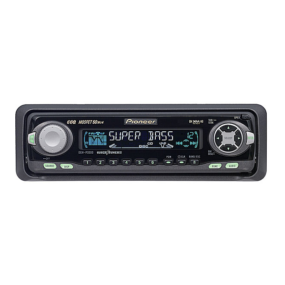
MULTI-CD CONTROL HIGH POWER CD PLAYER WITH FM/AM TUNER
DEH-P4350
DEH-P3350
DEH-P3350B
- This service manual should be used together with the following manual(s):
Model No.
Order No.
CX-958
CRT2423
CONTENTS
1. SAFETY INFORMATION ............................................2
2. EXPLODED VIEWS AND PARTS LIST .......................3
4. PCB CONNECTION DIAGRAM ................................28
5. ELECTRICAL PARTS LIST ........................................36
6. ADJUSTMENT..........................................................41
PIONEER CORPORATION
PIONEER ELECTRONICS SERVICE INC.
PIONEER EUROPE NV
Haven 1087 Keetberglaan 1, 9120 Melsele, Belgium
PIONEER ELECTRONICS ASIACENTRE PTE.LTD. 253 Alexandra Road, #04-01, Singapore 159936
C PIONEER CORPORATION 2000
DEH-P4350/X1N/ES
X1N/ES
Mech. Module
Remarks
S8.1
CD Mech. Module:Circuit Description, Mech. Description, Disassembly
4-1, Meguro 1-Chome, Meguro-ku, Tokyo 153-8654, Japan
P.O.Box 1760, Long Beach, CA 90801-1760 U.S.A.
X1N/ES
7. GENERAL INFORMATION .......................................45
7.1 DIAGNOSIS ........................................................45
7.1.1 TEST MODE ..............................................45
7.1.2 DISASSEMBLY .........................................49
7.1.3
7.2 PARTS .................................................................54
7.2.1 IC................................................................54
7.2.2 DISPLAY ....................................................59
7.3 OPERATIONAL FLOW CHART ...........................60
8. OPERATIONS AND SPECIFICATIONS.....................61
K-ZZB. DEC. 2000 Printed in Japan
ORDER NO.
CRT2576
X1N/ES
53
Advertisement
Table of Contents

Related Manuals for Pioneer DEH-P4350


Summary of Contents for Pioneer DEH-P4350
-
Page 1: Table Of Contents
PIONEER ELECTRONICS SERVICE INC. P.O.Box 1760, Long Beach, CA 90801-1760 U.S.A. PIONEER EUROPE NV Haven 1087 Keetberglaan 1, 9120 Melsele, Belgium PIONEER ELECTRONICS ASIACENTRE PTE.LTD. 253 Alexandra Road, #04-01, Singapore 159936 C PIONEER CORPORATION 2000 K-ZZB. DEC. 2000 Printed in Japan... -
Page 2: Safety Information
DEH-P4350,P3350,P3350B - CD Player Service Precautions 2. During disassembly, be sure to turn the power off 1. For pickup unit(CXX1285) handling, please refer since an internal IC might be destroyed when a con- to"Disassembly"(see page 49). nector is plugged or unplugged. -
Page 3: Exploded Views And Parts List
DEH-P4350,P3350,P3350B 2. EXPLODED VIEWS AND PARTS LIST 2.1 PACKING... - Page 4 - Parts marked by “*” are generally unavailable because they are not in our Master Spare Parts List. ∇ mark on the product are used for disassembly. - Screws adjacent to - PACKING SECTION PARTS LIST Part No. Mark No. Symbol and Description DEH-P4350/X1N/ES DEH-P3350/X1N/ES DEH-P3350B/X1N/ES 1-1 Owner’s Manual CRD3302...
- Page 5 DEH-P4350,P3350,P3350B 2.2 EXTERIOR...
- Page 6 DEH-P4350,P3350,P3350B (1) EXTERIOR SECTION PARTS LIST Mark No. Description Part No. Mark No. Description Part No. 1 Screw BMZ30P040FZK 46 Spring CBH2431 2 Screw BMZ30P100FMC 47 Spring CBH2491 3 Screw BSZ26P060FMC 48 Cover CNS6282 4 Screw BSZ30P060FMC 49 Holder CNV6505...
- Page 7 DEH-P4350,P3350,P3350B (2) CONTRAST TABLE DEH-P4350/X1N/ES, DEH-P3350/X1N/ES and DEH-P3350B/X1N/ES are constructed the same except for the following: Part No. Mark No. Symbol and Description DEH-P4350/X1N/ES DEH-P3350/X1N/ES DEH-P3350B/X1N/ES 6 Cord Assy CDE6494 Not used Not used 15 Tuner Amp Unit CWM7376 CWM7383...
- Page 8 DEH-P4350,P3350,P3350B 2.3 CD MECHANISM MODULE...
- Page 9 DEH-P4350,P3350,P3350B - CD MECHANISM MODULE SECTION PARTS LIST Mark No. Description Part No. Mark No. Description Part No. 1 Control Unit CWX2411 46 ••••• 2 Connector(CN802) CKS2192 47 Ball CNR1189 3 Connector(CN801) CKS2193 48 Belt CNT1086 4 Connector(CN701) CKS2773 49 Roller...
-
Page 10: Block Diagram And Schematic Diagram
DEH-P4350,P3350,P3350B 3. BLOCK DIAGRAM AND SCHEMATIC DIAGRAM 3.1 BLOCK DIAGRAM TUNER AMP UNIT FM/AM TUNER UNIT FM/AM 1ST IF 10.7MHz MPXREF 41kHz AMRF T51 Q51 CF51 CF52 CF53 AMDET AMANT L ch IC 2 FM MPX R ch ANT ADJ COMP MIXER, IF AMP, DET. - Page 11 DEH-P4350,P3350,P3350B RESET IC 603 Q913 S-80834ANY CN901 Q909 BACK UP BACK UP Q610 adpw AVREF SYSTEM DALMON CONTROLLER Q914 bsens IC 601(1/2) PE5203A Q915 asens Q917 isens pce@ LOCL LOCH PCE1 ASENBO 86 85 24 ELECTRONIC VOLUME/ POWER AMP SOURCE SELECTOR TUN L RL—...
- Page 12 DEH-P4350,P3350,P3350B 3.2 OVERALL CONNECTION DIAGRAM(GUIDE PAGE) Note: When ordering service parts, be sure to refer to “EXPLODED VIEWS AND PARTS LIST” or “ELECTRICAL PARTS LIST”. Large size SCH diagram Guide page Detailed page ANTENNA DSP-201M EJECT SENSE SW IMH3A CL220PGC...
- Page 13 DEH-P4350,P3350,P3350B TUNER AMP UNIT IP-BUS:+2.2dBs PML008A P4350 IMH3A FM(100%): +3.6dBs AM(30%): -6.9dBs CD:+10.2dBs IP-BUS:+10.3dBs CD:+9.4dBs IMH3A PE5203A 600µH SYSTEM CONTROLLER > FUSE CEK1136 10A DTC124EK DETACH SENSE SW R934 R789 222 (1/10W) FM(100%):+29.6dBs R935 AM(30%):+19.1dBs R788 222 (1/10W) CD:+36.2dBs IP-BUS:+36.3dBs...
- Page 14 DEH-P4350,P3350,P3350B...
- Page 15 DEH-P4350,P3350,P3350B A-a B...
- Page 16 DEH-P4350,P3350,P3350B...
- Page 17 DEH-P4350,P3350,P3350B...
- Page 18 DEH-P4350,P3350,P3350B 3.3 KEYBOARD UNIT(DEH-P4350/X1N/ES, DEH-P3350/X1N/ES) REMOTE CONTRO P3350 SENSOR P4350 P4350:151 P3350:201 PROG PURE GREEN BAND PURE GREEN DOWN...
- Page 19 DEH-P4350,P3350,P3350B E CONTROL KEYBOARD UNIT NSOR P4350 P4350:CL170UBX SFEQ AUDIO P3350:CL170PGCD FUNC DISP SOURCE RIGHT LEFT...
- Page 20 DEH-P4350,P3350,P3350B 3.4 KEYBOARD UNIT(DEH-P3350B/X1N/ES) PROG SUPER RED BAND SUPER RED DOWN...
- Page 21 DEH-P4350,P3350,P3350B KEYBOARD UNIT CL170SRCD SFEQ AUDIO FUNC DISP SOURCE RIGHT LEFT...
-
Page 22: Cd Mechanism Module
DEH-P4350,P3350,P3350B 3.5 CD MECHANISM MODULE CONTROL UNIT PICKUP UNIT (SERVICE)(P8) CN101 RF-AMP, SE CL203IRXTU CL203IRXTU PHOTO UNIT(S8) CN802 Q1 CPT230SX-TU Q2 CPT230SX-TU SPINDLE MOTOR M3 CXB2562 CARRIAGE MOTOR M1 CXB2190 LOADING MOTOR CD DRIVER M2 CXB2195 CN801 BA05SFP 5V REGULATOR... - Page 23 DEH-P4350,P3350,P3350B SWITCHES: CONTROL UNIT S801 : HOME SWITCH..ON-OFF S802 : CLAMP SWITCH..ON-OFF The underlined indicates the switch position. NOTE : Symbol indicates a resistor. No differentiation is made between chip resistors and discrete resistors. Symbol indicates a capacitor. No differentiation is made between chip capacitors and discrete capacitors.
- Page 24 DEH-P4350,P3350,P3350B Note:1. The encircled numbers denote measuring pointes in the circuit diagram. 2. Reference voltage REFO:2.5V - Waveforms 1 RFI 1 CH1: RFI 1 CH1: RFI 0.5V/div. 0.5µs/div. 1V/div. 1V/div. 0.5ms/div. 0.5ms/div. 2 CH2: MIRR 2 CH2: MIRR Normal mode: play 5V/div.
- Page 25 DEH-P4350,P3350,P3350B 8 CH1: TE 8 CH1: TE 0 MD 0.2V/div. 0.5V/div. 0.5V/div. 0.1s/div. 20ms/div. 5ms/div. 9 CH2: TD ! CH2: SD 0.2V/div. 0.5V/div. Normal mode: play TEST mode: 100 Tracks jump(FWD) Normal mode: Play (12cm) → REFO → REFO →...
- Page 26 DEH-P4350,P3350,P3350B ( CH1: R OUT 8 CH1: TE 6 CH1: FE 1V/div. 0.2V/div. 0.2V/div. 1ms/div. 0.2ms/div. 1ms/div. ) CH2: L OUT 3 CH2: FD 9 CH2: TD 1V/div. 0.5V/div. 0.5V/div. Normal mode: Play (1kHz 0dB) Normal mode: During AGC Normal mode: During AGC →...
- Page 27 DEH-P4350,P3350,P3350B...
-
Page 28: Pcb Connection Diagram
DEH-P4350,P3350,P3350B 4. PCB CONNECTION DIAGRAM CORD ASSY 4.1 TUNER AMP UNIT NOTE FOR PCB DIAGRAMS 1. The parts mounted on this PCB include all necessary parts for several destination. For further information for respective destinations, be sure to check with the schematic dia- gram. - Page 29 DEH-P4350,P3350,P3350B SIDE A CORD ASSY REAR OUTPUT IP-BUS INPUT ANTENNA JACK CN1950 FRONT...
- Page 30 DEH-P4350,P3350,P3350B TUNER AMP UNIT...
- Page 31 DEH-P4350,P3350,P3350B SIDE B...
- Page 32 DEH-P4350,P3350,P3350B 4.2 PANEL UNIT SIDE B SIDE A CN1901 CN750...
- Page 33 DEH-P4350,P3350,P3350B 4.3 KEYBOARD UNIT SIDE B SIDE A CN1951...
- Page 34 DEH-P4350,P3350,P3350B 4.4 CD MECHANISM MODULE SIDE A...
- Page 35 DEH-P4350,P3350,P3350B SIDE B...
-
Page 36: Electrical Parts List
DEH-P4350,P3350,P3350B 5. ELECTRICAL PARTS LIST NOTES: - Parts whose parts numbers are omitted are subject to being not supplied. - The part numbers shown below indicate chip components. Chip Resistor RS1/_S___J,RS1/__S___J Chip Capacitor (except for CQS..) CKS.., CCS.., CSZS..=====Circuit Symbol and No.===Part Name Part No. - Page 37 DEH-P4350,P3350,P3350B =====Circuit Symbol and No.===Part Name Part No. =====Circuit Symbol and No.===Part Name Part No. ------ ------------------------------------------ ------------------------- ------ ------------------------------------------ ------------------------- RS1/16S473J RS1/16S153J RS1/16S472J RS1/16S153J RS1/16S473J RS1/16S222J RS1/16S681J RS1/16S433J RS1/16S681J RS1/16S473J RS1/16S473J RS1/16S102J RS1/16S473J RD1/4PU222J RS1/16S0R0J RS1/16S102J RS1/16S0R0J RS1/16S222J RS1/16S272J...
- Page 38 DEH-P4350,P3350,P3350B =====Circuit Symbol and No.===Part Name Part No. =====Circuit Symbol and No.===Part Name Part No. ------ ------------------------------------------ ------------------------- ------ ------------------------------------------ ------------------------- CKSRYB105K6R3 Unit Number : CWM7398 (DEH-P4350/X1N/ES) CKSRYB102K50 Unit Number : CWM7405 (DEH-P3350/X1N/ES) CEJA100M16 Unit Name : Keyboard Unit CKSRYB104K16...
- Page 39 DEH-P4350,P3350,P3350B =====Circuit Symbol and No.===Part Name Part No. =====Circuit Symbol and No.===Part Name Part No. ------ ------------------------------------------ ------------------------- ------ ------------------------------------------ ------------------------- 1942 RS1/16S131J 1919 RS1/16S131J 1943 RS1/16S131J 1920 RS1/16S131J 1945 RS1/16S121J 1927 RS1/16S472J 1946 RS1/16S0R0J 1929 RS1/16S0R0J 1949 RS1/16S151J 1930...
- Page 40 DEH-P4350,P3350,P3350B =====Circuit Symbol and No.===Part Name Part No. =====Circuit Symbol and No.===Part Name Part No. ------ ------------------------------------------ ------------------------- ------ ------------------------------------------ ------------------------- RS1/16S102J Unit Number : RS1/16S0R0J Unit Name : Photo Unit(S8) RS1/16S0R0J RS1/8S751J Photo-transistor CPT230SX-TU RS1/8S751J Photo-transistor CPT230SX-TU RS1/16S0R0J Miscellaneous Parts List...
-
Page 41: Adjustment
DEH-P4350,P3350,P3350B 6. ADJUSTMENT 6.1 CD ADJUSTMENT 1) Precautions 2) Test Mode This mode is used for adjusting the CD mechanism • This unit uses a single power supply (+5V) for the reg- ulator. The signal reference potential, therefore, is module of the device. - Page 42 DEH-P4350,P3350,P3350B - Flow Chart Test Mode In Acc on SOURCE Sourse CD New test mode BAND Power ON (Adjustment for T.Offset) Power ON RF AMP Gain Select (Not adjustment for T.Offset) 00 00 00 Display 99 99 99 GG GG GG...
-
Page 43: Checking The Grating After Changing The Pickup Unit
DEH-P4350,P3350,P3350B 6.2 CHECKING THE GRATING AFTER CHANGING THE PICKUP UNIT • Note : The grating angle of the PU unit cannot be adjusted after the PU unit is changed. The PU unit in the CD mecha- nism module is adjusted on the production line to match the CD mechanism module and is thus the best adjusted PU unit for the CD mechanism module. - Page 44 DEH-P4350,P3350,P3350B Ech → Xch 20mV/div, AC Grating waveform Fch → Ych 20mV/div, AC 0° 30° 45° 60° 75° 90°...
-
Page 45: General Information
DEH-P4350,P3350,P3350B 7. GENERAL INFORMATION 7.1 DIAGNOSIS 7.1.1 TEST MODE - Error Messages If a CD is not operative or stopped during operation due to an error, the error mode is turned on and cause(s) of the error is indicated with a corresponding number. This arrangement is intended at reducing nonsense calls from the users and also for facilitating trouble analysis and repair work in servicing. - Page 46 DEH-P4350,P3350,P3350B - New Test Mode S-CD plays the same way as before. If an error such as off focus, spindle unlocking, unreadable sub-code, or sound skipping occurs after setup, its cause and time occurred (in absolute time) are displayed. During setup, operational status of the control software (internal RAM: CPOINT) is displayed.
- Page 47 DEH-P4350,P3350,P3350B (4) Display of Operational Status (CPOINT) during Setup Status No. Contents Protective action CD+5V ON process in progress. None Servo LSI initialization (1/3) in progress. None Servo LSI CRAM initialization in progress. None Servo LSI initialization (2/3) in progress.
- Page 48 DEH-P4350,P3350,P3350B (5) Display Examples 1) During Setup (When status no. = 11) TRK No. MIN. SEC. 11" 2) During Operation (TOC read, TRK search, Play, FF and REV) The same as in the normal mode. 3) When a Protection Error Occurred Switch to the following displays (A) and (B) using the [BAND] switch: (A) Error occurrence timing display in absolute time.
-
Page 49: Disassembly
DEH-P4350,P3350,P3350B 7.1.2 DISASSEMBLY Removing the Case (not shown) 1. Remove the Case. CD Mechanism Module Removing the CD Mechanism Module (Fig.1) Remove the four screws. Disconnect the connector and then remove the CD Mechanism Module. Removing the Grille Panel Assy (Fig.1) Remove the two screws and then remove the Grille Panel Assy. - Page 50 DEH-P4350,P3350,P3350B - Removing the Upper Frame 1. Remove six Springs A, two Springs B and four Screws. Upper Frame 2. Remove two Tabs situated on rear side of the Upper Frame, remove two Arms on the front side, then remove two Tabs on the front side.
- Page 51 DEH-P4350,P3350,P3350B - Removing the Guide Arm Assy 1. Remove a connector, a spring A and B 2. Drive the Guide Arm Assy up aslant into rear side Guide Arm Assy Section direction, then remove it from a Pin. Finally, drive the assembly approximately 45 degrees upward, then slide the assembly toward left side to remove it.
- Page 52 DEH-P4350,P3350,P3350B - Removing the Loading Motor and Carriage Motor Guide 1. Remove the Spring and two Screws A. 2. Dismount the Loading Motor. 3. Remove the Belt, a Screw B, two Screws C, a Guide and a Screw Unit. Screw Unit Carriage Motor 4.
-
Page 53: Connector Function Description
DEH-P4350,P3350,P3350B 7.1.3 CONNECTOR FUNCTION DESCRIPTION 1. BUS+ 2. GND 3. GND 4. NC 5. BUS- 6. GND 7. BUS L+ INPUT 8. ASENB 9. BUS R+ INPUT 10. BUS R- INPUT FRONT FUSE 10A 11. BUS L- INPUT OUTPUT 1. RR+ 2. -
Page 54: Parts
DEH-P4350,P3350,P3350B 7.2 PARTS 7.2.1 IC PAL006A Protector; Over voltage Reference amp_vcc Stand-by P-GND2 Circuit OUT2- Offset Protector; STBY Detection Thermal OUT2+ OUT1- Offset P-GND1 Detection OUT1+ Protector; S-GND Short circuit AC-GND OUT3+ Offset P-GND3 Detection OUT3- OUT4+ Offset MUTE Detection... - Page 55 DEH-P4350,P3350,P3350B PML008A Sel_out_L Sel_out_R Isolator circuit Rch block (same as Lch) PV_in_L PV_in_R Source Gain adjuster Tone_out_FR Tone_out_FL to Rch from Rch Primary volume (L+R) SV_in_FL SV_in_FR Loudness Treble Middle Bass volume Anti Alias Tone_out_RL Tone_out_RR filter SV_in_RR SV_in_RL Anti radiation...
- Page 56 DEH-P4350,P3350,P3350B - Pin Functions (PE5203A) Pin No. Pin Name Function and Operation Not used dsens Grille detach sense input Not used EJECTIN Eject sense input TESTIN Test program mode input LCDPW LCD back light power supply control output TELIN Telephone mute input...
- Page 57 DEH-P4350,P3350,P3350B Pin No. Pin Name Function and Operation xrst CD:LSI reset control output xstb CD:LSI strobe output ASENBO IP-BUS:Slave power supply control output MUTE E.VOL:Mute control output TEST(GND) TUNER:Signal level input Not used MODELIN Model select input CSENS Flap close sense input...
- Page 58 DEH-P4350,P3350,P3350B FM/AM TUNER UNIT FM/AM 1ST IF 10.7MHz MPXREF 41kHz AMRF T51 Q51 CF51 CF52 CF53 AMDET AMANT L ch IC 2 FM MPX R ch ANT ADJ COMP MIXER, IF AMP, DET. LDET FMANT RFGND FMRF CF202 IC 3...
-
Page 59: Display
DEH-P4350,P3350,P3350B 7.2.2 DISPLAY - CAW1626(DEH-P4350/X1N/ES), CAW1628(DEH-P3350/X1N/ES), CAW1679(DEH-P3350B/X1N/ES) -
Page 60: Operational Flow Chart
DEH-P4350,P3350,P3350B 7.3 OPERATIONAL FLOW CHART Power ON VDD=5V 19pin bsens 93pin bsens=L asens 92pin asens=L dsens 2pin dsens=L adpw←H 22pin ASENBO←H 71pin csens - 2V<CSENS<4V , 77pin Source returns to the original one(before you open). 2V<CSENS<4V CD, MD and TAPE loading functions are available. -
Page 61: Operations And Specifications
FUNCTION button DISPLAY button BAND button Remote Controller (DEH-P4350) DEH-P4350 is equipped with a remote controller for convenient operation. Operation is the same as when using buttons on the head unit. +/– button Raise or lower the volume. FUNCTION button AUDIO button 5/∞/2/3 buttons... - Page 62 DEH-P4350,P3350,P3350B...
- Page 63 DEH-P4350,P3350,P3350B...
- Page 64 DEH-P4350,P3350,P3350B...
- Page 65 DEH-P4350,P3350,P3350B...
- Page 66 DEH-P4350,P3350,P3350B - CONNECTION DIAGRAM...
-
Page 67: Specifications
DEH-P4350,P3350,P3350B 8.2 SPECIFICATIONS General CD player Power source ..14.4 V DC (10.8 – 15.1 V allowable) System ........Compact disc audio system Grounding system ........Negative type Usable discs ..........Compact disc Max. current consumption ........10.0 A Signal format ....Sampling frequency: 44.1 kHz Dimensions Number of quantization bits: 16;...