Advertisement
Quick Links
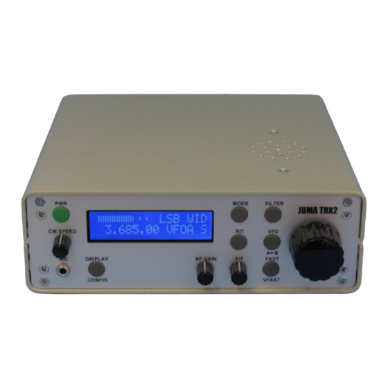
The TRX-2 is an all-band QRP transceiver utilising a direct digital synthesiser and employing
quadrature phase-shift detection in a direct-conversion arrangement for both transmission and
reception, and capable of USB/LSB and CW modes of operation.
This document describes the operation and setup of this equipment using firmware version
1.07m, software modifications and changes made by Adrian Ryan, 5B4AIY.
It assumes that you have already performed the various hardware setup adjustments covering
receiver AGC threshold setting, optimisation of sideband suppression, transmitter final
amplifier bias current adjustments, amplifier gain compensation and microphone level setting.
Front Panel Controls
Control Description
PWR
This button is used to power-up and power-down the transceiver, as well as several secondary
functions. To power up the transceiver, briefly press the button. The display will illuminate
and a sign-on message will be displayed:
JUMA-TRX2 v1.07m
OH2NLT OH7SV
After a short delay, the current frequency bands in use will be displayed either as:
IARU Freq Bands
or:
USA Freq Bands
Then the main display will be shown.
JUMA TRX-2 Operating Manual
5B4AIY Firmware Version 1.07m
1
Advertisement

Summary of Contents for JUMA TRX-2
- Page 1 JUMA TRX-2 Operating Manual 5B4AIY Firmware Version 1.07m The TRX-2 is an all-band QRP transceiver utilising a direct digital synthesiser and employing quadrature phase-shift detection in a direct-conversion arrangement for both transmission and reception, and capable of USB/LSB and CW modes of operation.
- Page 2 To power down the transceiver, press and hold the power button, and a message will be displayed showing a count-down to zero. At this point the display will clear, the backlighting will be turned off, and the button can be released. During the count down period the current user settings are being written to the EEPROM.
- Page 3 DISPLAY/CONFIG This multi-function button is normally used to control the transceiver’s display. In the receive mode the normal display has the S-meter, either as a numeric or graphic indication at the top left of the screen, followed by the mode indicator, (LSB/USB/CW/Tune), and the receiver’s filter, Wide (WID), Medium (MID), or Narrow (NAR).
- Page 4 To copy from a VFO memory to the active VFO, turn the VFO knob anti-clockwise, and the source will decrement until you get to VFOA. The direction arrow will reverse showing that the direction of the transfer is from the VFO memory to an active VFO. In the example above, VFO memory J, whose frequency and mode are displayed on the lower line, is being copied to the active VFO, A.
- Page 5 If this is invoked, the top line of the display will show the band to be selected, from 160 – 10 metres. If the current receiver’s frequency is within an amateur band, then the selection will display this band, and the lower frequency display will show the selected frequency. If the frequency is not within a recognised amateur band, then the out-of-band indicator will show on the main display, and the 160m band’s frequency will be shown, as illustrated above.
- Page 6 Split Mode Copy, VFOA to VFOB To copy the VFO-B frequency to VFO-A, first select VFO-B, and press and hold the button, and a similar display will be shown except that the source will be VFOB, and the destination will be VFOA. If the button is pressed and held whilst the Splt is displayed, this is the same as VFO-A to VFO-B.
- Page 7 To enter the System Calibration & Setup menu, turn the transceiver off, and then press and hold the power button until the message: JUMA-TRX2 v1.07m Service Mode is displayed. To cycle through the various setting screens, briefly press the DISPLAY button.
- Page 8 It is also possible to use a less accurate frequency counter if you can tune to a standard frequency transmission. These are usually maintained to an accuracy of better than 0.1ppm. For an example of how to use this method, please refer to Annex B. The range of the input setting is checked, and there is an adjustment range of ±20kHz.
- Page 9 type PMBFJ112, and the threshold voltage of this transistor differs from that of the SST112. This leads to a significant difference in the two calibration settings. In both cases, the adjustment procedure involves terminating the receiver in a 50Ω dummy load, rotating R53 fully anticlockwise to achieve maximum gain, and then carefully rotating clockwise until the audio noise just starts to decrease.
- Page 10 Overcurrent Trip (Adjustment) Default: 2.5A This is a new feature. Adjust the limit to a suitable value. The default is usually satisfactory. The value can be set from 1.5A – 3.0A. Temporarily setting the trip to 1.5A allows you to verify that it is working.
- Page 11 Acknowledge and cancel the warning by briefly pressing the PWR button. This warning will only be given once – it will NOT repeat! Once you have acknowledged the warning it disappears. The only way to reset it is to power the transceiver off and back on again. The next screen displays the message: Push FAST long = factory defaults...
- Page 12 Speech Processor Default: OFF The transceiver is equipped with a simple speech processor which uses a soft-clipping method to achieve a higher peak to average ratio for speech to increase the average talk- power. However, this also leads to a certain amount of distortion, and thus this setting has to be carefully related to the transmit SSB gain setting, R26.
- Page 13 Default: Yaesu CAT This setting governs a number of peripheral features. It can be set to the following modes: JUMA TRX2 This mode is used to enable serial communication with the companion JUMA PA100D 100W linear amplifier. Yaesu CAT This allows communication with PC logging programs, and emulates a Yaesu transceiver. For a list of commands that are emulated, please see Annex C.
- Page 14 VFO Memory Operation Default: A/B + Split This setting governs how the various VFO memories are used and organised. The settings range from A/B + Split mode, to 3 – 26 memories. Split mode operation involves transmitting on one frequency, and receiving on another. The frequencies can be anywhere in the tuning range of the transceiver.
- Page 15 Even if this feature is turned off, the receive annunciator is still displayed, and storage of a frequency in the User Band memory is inhibited. Auto Sideband Select Default: ON This is a new feature. Conventionally, for frequencies above 10MHz USB is the preferred mode for voice communication, conversely, LSB for frequencies lower than 10MHz.
- Page 16 Fast Tuning Rate – 100Hz Very Fast Tuning Rate – 10kHz Note that the precision is not affected, the display is merely rounded to the appropriate tuning rate’s resolution, but selecting a higher resolution tuning rate will reveal the rounded digits. With version 1.07g and later, the accuracy of the synthesiser has been improved.
- Page 17 Band S/W Default: Default This is a new feature. This setting governs how the Rapid Bandswitch feature operates. Default In this mode, when selecting an amateur band, the frequency used will be fixed at the band’s centre. BAND FREQUENCY MHz 160 metres 1.900 80 metres...
- Page 18 Include RIT Default: NO This is a new feature. If this is turned on, then the RIT offset frequency will be used to modify the frequency displayed to show the actual receive frequency. Band Limits Default: IARU This is a new feature. The transceiver’s band edge frequencies can be set to either the IARU Region 1 limits, or the USA limits.
- Page 19 The filter change points for the 2MHz and 4MHz filters have been moved up by 10kHz. It was particularly disconcerting that right at the 2.0MHz and 4.0MHz frequencies these filters would be changed. The new frequencies are 2.010MHz, and 4.010MHz. The Serial Test facility has been enhanced with the addition of a dump of the attenuator settings corresponding to the various internal filters.
- Page 20 Annex A JUMA Frequency Step Accuracy The Juma TRX2 using firmware revision 1.06 has an inherent frequency resolution of 10Hz. This means that the actual frequency to which the transceiver is tuned is within ±5Hz of the displayed frequency, if we neglect the reference oscillator errors. Or is it? If we carefully examine the frequency display, we can observe some interesting quirks.
- Page 21 amateur band this represents a tuning accuracy of ±2.5ppm, and even better at the higher frequencies. But, I’m a perfectionist, you might even say obsessive, and it occurred to me that the synthesiser could do better. After all, when you increment the DDS word by 1 the local oscillator’s frequency changes by 0.020955 Hz, and thus there is the potential for the transceiver’s actual resolution accuracy to be improved by a factor of 250.
- Page 22 Annex B Reference Oscillator Calibration The accuracy of the reference oscillator determines the overall frequency accuracy of the transceiver. The master oscillator is the 30MHz package oscillator on the DDS board, and its output is used both to clock the microprocessor, as well as provide the reference for the DDS synthesiser chip.
- Page 23 Connect the frequency counter to the phone output socket, and adjust the audio gain for a suitable level to trigger the counter. In order to avoid excessive jitter the signal must be reasonably clean and reasonably free from noise. Set the frequency counter to display to 1Hz using the 10 second time-base. Make at least 10 measurements, and average the results to 2 decimal places.
- Page 24 Reference Oscillator Frequency = 29,999,696.40 * 6 = 179,998,178Hz In this case, the crystal oscillator was low by about 10ppm. Now an example where the oscillator is high in frequency. For this example, assume the standard frequency is 10MHz. Tune the receiver to a display setting of: 10.001000MHz, LSB.
- Page 25 : 14 54 32 10 xx xx is the mode byte, with the following meaning: 00 = LSB, 01 = USB, 02 = CW There are a number of other values, but they are not applicable to the Juma TRX-2 Read RX Status...
- Page 26 Squelch Status 0 = OFF, Signal present, 1 = ON, Receiver squelched CTCSS/DCS code. For Juma = 0 Discriminator Centering, for SSB/CW = 0 Dummy Data 0 S-Meter Bit 3 S-Meter Bit 2 S-Meter Bit 1 S-Meter Bit 0 The S-meter value is coded into 15 levels from S0 to S9+40dB...
- Page 27 PTT OFF (Receive) Command To Transceiver : 00 00 00 00 88 Lock VFO Command To Transceiver : 00 00 00 00 00 Unlock VFO Command To Transceiver : 00 00 00 00 80...
- Page 28 Annex D Kenwood TS-480 CAT Command Emulation If the RS-232 serial port mode is set to Kenwood CAT, then the transceiver will respond to the following command sequences: Read/Set VFO-A Frequency : FA Read/Set VFO-B Frequency : FB Select/Read Receiver VFO : FR Select/Read Fine Tune : FS...
- Page 29 Read VFO-B Frequency Transmitted from PC Response from TS-480 (Assume the frequency is: 14.195MHz) FB00014195000; Select Receiver VFO Transmitted from PC FR0; Select VFO-A FR1; Select VFO-B Read Receiver VFO Transmitted from PC Response from TS-480 FR0; VFO-A selected FR1; VFO-B selected Select Fine Tune (1Hz) Transmitted from PC FS0;...
- Page 30 Read transceiver ID number Transmitted from PC Response from TS-480 ID020; Read Transceiver Status Transmitted from PC Response from TS-480 IFp1p1p1p1p1p1p1p1p1p1p1p2p2p2p2p2p3p3p3p3p3p4p5p6p7p7p8p9p10p11p12p13p14p1 4p15; : 11 digits of receiver frequency to 1Hz, example: 14.234567MHz = 00014234567 : 5 spaces : RIT frequency ±nnnn Hz : 0 = RIT Off, 1 = RIT On : 0 = XIT Off, 1 XIT On (Not Applicable) : 0 (Always 0)
- Page 31 Read Current Mode Transmitted from PC Response from TS-480 (Other modes are possible, but not applicable to a TRX-2) MD1; LSB MD2; USB MD3; CW Set Noise Blanker Transmitted from PC NB0; Noise Blanker OFF NB1; Noise Blanker ON Read Noise Blanker...
- Page 32 00: 10, 01: 50, 02: 100, 03: 200, 04: 300, 05: 400, 06: 500, 07: 600, 08: 700, 09: 800, 10: 900, 11: 1000, all frequencies in Hz. The Juma emulation ignores this command. Read Low Frequency DSP Settings...
- Page 33 Response from TS-480 SM0nnnn; SM1nnnn; SM2nnnn; SM3nnnn; Where nnnn is 0000 – 0030 (main receiver) 0000 – 0015 (Sub receiver) Turn TX ON Transmitted from PC TX0; Transmit from MIC (TS-480) Transmit (TS-2000) If TS-2000 is already in transmit mode, response is ?; otherwise no response.
- Page 34 Set the terminal program to the same settings as the TRX-2, typically, 9600 Baud, 8 data bits, 1 stop bit, no parity. If the terminal is connected and the transceiver powered up, the following data will be printed: JUMA-TRX2 Copyright OH7SV &...
- Page 35 The above display show the A-D convertor output when using the factory default values for the measurement system. The next dump shows a more representative set of values obtained when keying the transceiver in the Tune mode operating into a dummy load: A-D Convertor Samples Channel Sample...
- Page 36 System Settings Reference Oscillator: 180000000 Hz DC Voltmeter : 5370 Ammeter : 2414 Power Meter : 3550 S-Meter : 3634 SWR Trip Setting Over-Voltage Trip : 2756 = 14.80V Under-Voltage Trip : 2049 = 11.00V Over-Current Trip : 2485 = 3.00A Beep Time 50 mS...
- Page 37 You will receive a prompt requesting you to enter a digit of 0, 1, 2, 4, 8, or 9. The software will ignore other responses. The alarms are saved as flags in a single word, entering an appropriate digit will set that alarm flag, and the display will blink with the alarm message, and beep.
- Page 38 15MHz -1dB 19MHz -1dB 23MHz -1dB 26MHz -1dB 28MHz -1dB -------------------- These attenuator settings are the factory defaults; to equalise the RF output power across the amateur bands, the attenuation factors can be changed. Please refer to Annex H for further details.
- Page 39 Annex F Improved Accuracy Measurement Sub-System The original measurement sub-system, whilst sufficient for general purpose indications of the voltage, current and power output of the transceiver, did not completely capitalise on the inherent accuracy available from a 12-bit A-D convertor. The designers chose to optimise the speed of the main processing loop in the software, and used calibration constants and factors that lent themselves to easy integer manipulation, avoiding the use of floating point mathematics.
- Page 40 In the original firmware the actual calculation was: = (ADC * Calibration Factor) / 256 display If we insert some typical values, then the ADC value for 13.8V will be around 2629, and the default calibration value is 135, and thus: = (2629 * 135) / 256 display = 354915 / 256...
- Page 41 13.8 * 10100 / (10100 + 32670) = 13.8 * 10100 / 42770 = 3.25883V The tolerance of the voltage regulator’s output is ±0.25V, and thus the lowest count from the A-D convertor will occur for the lowest input voltage and the highest reference voltage, and would be a count of: 2465.
- Page 42 currents for both the driver and power amplifier stages, it is essential that the current measurements are performed to as high an accuracy as possible. The output current measurement is made by sampling the voltage developed across two low value resistors connected in parallel, R23 and R24, each of 0.22Ω. This gives a shunt resistance of 0.11Ω...
- Page 43 = 1679 This has to be squared: 2,819,041 the calibration factor to read 10W is therefore: 3547 The incremental quantisation step is thus 2.8mW, which is a greater precision than actually required, nevertheless, the accuracy of the measurement is now largely determined by the sensor, and not the A-D convertor or its calibration factor.
- Page 44 Annex G The TRX2 Alarm System Version 1.07k of the firmware introduces an additional feature to the transceiver, an alarm system to provide the user with a critical warning of potentially damaging factors. The system can provide a warning for high SWR, power amplifier over-current, and over and under input voltages.
- Page 45 periods of time input voltages up to about +15V, it is unwise to continue to use it if you experience a significant number of over-voltage alarms. Under-Voltage Low input voltages are not damaging to the transceiver, but are worth investigating. If the equipment is being operated under portable conditions, then it is likely that the power supply will be a small sealed lead-acid battery.
- Page 46 Annex H Equalising the TRX-2 Output Power The Juma TRX-2 has a somewhat ‘hidden’ feature whereby you can set the output power of the transmitter on all bands to be essentially the same despite minor variations in insertion loss of filters, and the varying gain of the output amplifier with frequency.
- Page 47 Examine the results, and set the attenuators such that on the band with the lowest output power the attenuator is set to 0dB, and the other band’s attenuator setting give a matching output power. In my case this would be: Band: Atten: Atten:...
Need help?
Do you have a question about the TRX-2 and is the answer not in the manual?
Questions and answers