Table of Contents
Advertisement
Document Type: Service Manual
Version 1.2 10272017
SERVICE MANUAL
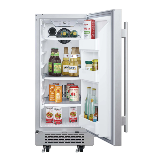
Single Zone Cooler
MODEL:
AFR151SSOD, AFR151SS, ABR151SG, AWC151SZ, ABR241SG,
AWC241SZ, AFR241SS, AFR241SSOD, AWC241TSZ, AWC241FD
CAUTION: READ ALL SAFETY PRECAUTIONS IN THIS
MANUAL BEFORE SERVICING THE UNIT
EdgeStar, 8606 Wall St, Suite 1800, Austin, TX 78754
support.edgestar.com • service@edgestar.com • edgestar.com
*Warranty service should be performed by an authorized service representative only.
Advertisement
Table of Contents

Related Manuals for EdgeStar AFR151SS


Summary of Contents for EdgeStar AFR151SS
- Page 1 AWC241SZ, AFR241SS, AFR241SSOD, AWC241TSZ, AWC241FD CAUTION: READ ALL SAFETY PRECAUTIONS IN THIS MANUAL BEFORE SERVICING THE UNIT EdgeStar, 8606 Wall St, Suite 1800, Austin, TX 78754 support.edgestar.com • service@edgestar.com • edgestar.com *Warranty service should be performed by an authorized service representative only.
-
Page 2: Table Of Contents
CONTENTS SAFETY PRECAUTIONS ................................2 PARTS IDENTIFICATION ...............................3-12 DISASSEMBLY..................................12-19 DOOR .....................................12 GLASS SHELVES..................................13 WIRES SHELVES................................13-14 TOP LAMP………… ................................14 BROADSIDE LAMP................................14 COLD CATALYST SYSTEM..............................14 DISPLAY BOARD BOARD & CONTROL BOARD........................15 POWER BOARD & TRANSFORMER ............................15 SENSOR & FAN................................16-18 COMPRESSOR PTC STARTER & OVERLOAD PROTECTOR........…………… ……………….…….18 TROUBLESHOOTING.................................20-23 COMPRESSOR COMPONENTS ............................20... -
Page 3: Parts Identification
2. PARTS IDENTIFICATION Model:AFR151SSOD Models:CWR361FD - 3 -... - Page 4 2. PARTS IDENTIFICATION Models:AFR151SS Models:CWF340DZ - 4 -...
- Page 5 2. PARTS IDENTIFICATION Models:ABR151SG - 5 -...
- Page 6 2. PARTS IDENTIFICATION Models:AWC151SZ - 6 -...
- Page 7 2. PARTS IDENTIFICATION Models:ABR241SG Door Control Panel Shelf Door Lock - 7 -...
- Page 8 2. PARTS IDENTIFICATION Models:AWC241SZ Front Vent - 8 -...
- Page 9 2. PARTS IDENTIFICATION Models:AFR241SS - 9 -...
- Page 10 2. PARTS IDENTIFICATION Models:AFR241SSOD - 10 -...
- Page 11 2. PARTS IDENTIFICATION Models:AWC241TSZ - 11 -...
-
Page 12: Door
2. PARTS IDENTIFICATION Models:AWC241FD - 12 -... -
Page 13: Disassembly
3. DISASSEMBLY 3-1 DOOR (Models:AFR151SSOD, AFR151SS, ABR151SG, (Model:AFR241SS, AFR241SSOD) AWC151SZ, , ABR241SG, AWC241SZ, AFR241SS, 1. Open the door completely. AFR241SSOD, AWC241FD Loosen 2 bolts securing the lower door axis to the lower 2. Remove all of the contents loaded on the shelf, if hinge to remove the door. -
Page 14: Top Lamp
Continue to pull the shelf forward until it is completely removed from the inner compartment. (Figure 7) Figure 11 3-7 BROADSIDE LAMP (Models:AFR151SSOD, AFR151SS, ABR151SG, AWC151SZ, , ABR241SG, AWC241SZ, AFR241SS, AFR241SSOD, AWC241TSZ, AWC241FD.) 1Pull the lamp cover. Separate the claw attached to the LED light. Separate the Figure7 lead wire housing. -
Page 15: Display Board Board & Control Board
6. Remove the display cover. Pull out the display board support 3-8 DISPLAY BOARD & CONTROL BOARD and find out the display board inside it. (figure 17) (Models:AFR151SSOD, AFR151SS, ABR151SG, AWC151SZ, , ABR241SG, AWC241SZ, AFR241SS, AFR241SSOD, AWC241TSZ, AWC241FD) 1. Loosen four screws. -
Page 16: Sensor & Fan
3. DISASSEMBLY (Models:AFR151SSOD, AFR151SS, ABR151SG, (Models:,ABR151SG, AWC151SZ) AWC151SZ 1.1 Loosen six screws. Pull out the rear air duct cover. 1. Loosen three screws. (figure 21) (figure 24) Carbon Filter Figure 21 Screw Sensor The power board & transformer are like below. (figure 22) - Page 17 3. DISASSEMBLY Loosen 1 screw to replace the sensor & fan. (Models: ABR241SG, AWC241SZ ) (figure 29) Loosen six screws. Pull out the rear air duct cover. (figure 26) wire housing Carbon Filter screw evaporator defrost Screw sensor Figure 29 cold catalyst (Models:AWC241TSZ) 1、...
-
Page 18: Compressor Ptc Starter & Overload Protector
1、 Open the box near compressor, The starter and overload Figure 33 protector are located inside. (figure 37) 3-11 COMPRESSOR PTC STARTER & OVERLOAD PROTECTOR (Models:AFR151SSOD, AFR151SS,ABR151SG, AWC151SZ, ABR241SG, AWC241SZ,AFR241SS, AFR241SSOD) 1. Open the box near compressor, the starter and overload protector are located inside. (figure 34) Figure 37... -
Page 19: Disassembly
3. DISASSEMBLY 2、 Dismantle the compressor PTC starter and overload protector. (figure 38) 2、 Remove the compressor junction box. (figure 41) Figure 38 The compressor PTC starter and overload protector is pictured below. (figure 39) Figure 41 3、 The compressor PTC starter and overload protector is pictured below. -
Page 20: Troubleshooting
3. DISASSEMBLY 4-1 COMPRESSOR COMPONENTS Check the Check the resistance resistance of among M-C, S-C and Motor M-S in Motor Replace Compressor. Compressor. Compressor. Is it normal? Check the resistance Check the of two terminals in resistance of PTC-Starter. Replace Is it normal? PTC-Starter. -
Page 21: Another Electric Component
4. TROUBLESHOOTING 4-2 ANOTHER ELECTRIC COMPONENTS ▼ Cooling is impossible Compressor doesn't run. Check if current flows to the Cause. following components. a. Starting devices Shorted or broken. Poor contacting b. OLP or shorted. c. Compressor coil Coil shorted. Replace Poor contacting d. -
Page 22: Service Diagnosis Chart
4. TROUBLESHOOTING 4-3 SERVICE DIAGNOSIS CHART Problem Possible Cause Appliance does not operate. Not plugged in. The appliance is turned off. The circuit breaker tripped or a blown fuse. Appliance is not cold enough. Check the temperature control setting. External environment may require a higher setting. -
Page 23: Refrigerating Cycle
4. TROUBLESHOOTING 4-4 REFRIGERATING CYCLE ▼ Troubleshooting Chart CAUSE STATE OF UNIT STATE OF EVAPORATOR TEMPERATURE COMMENTS OF COMPRESSOR • A little refrigerant discharges Appliance does PAR TIAL Low owing sound of A little high - • Normal cooling is possible when not get cold LEAKAGE Refrigerant is heard and... -
Page 24: Description Of Pcb
5. DESCRIPTION OF PCB (Models:AFR151SSOD / AFR151SS / ABR151SG / AWC151SZ / ABR241SG AWC241SZ AFR241SS AFR241SSOD AWC241TSZ) Figure 55 (Models:AWC241FD) Figure 57 - 24 -... - Page 25 DATE REVISION NOTES: 9/22/2017 Initial Document 10/16/2017 Minor text edits 10/27/2017 Minor text edits EdgeStar, 8606 Wall St, Suite 1800, Austin, TX 78754 support.edgestar.com • service@edgestar.com • edgestar.com *Warranty service should be performed by an authorized service representative only.
Need help?
Do you have a question about the AFR151SS and is the answer not in the manual?
Questions and answers