Table of Contents
Advertisement
NICE3000 User Manual
Thank you for using elevator integrated controller!
NICE 3000, the elevator integrated controller, is under the research and development of
and produced by Suzhou Monarch Control Technology Co. Ltd. It's the new vector-based
intelligent elevator integrated controller combining the elevator control with motor driver. NICE
3000 control system mainly consists of NICE 3000 elevator integrated controller, MCTC-CTB-A,
MCTC-HCB-A, MCTC-GCB-A, and MCTC-IE-A.
Main features are as follows:
More advanced
䅝
NICE 3000 including computer technology, Automatic control technology, Network
communication technology, and Motor vector drive technology, is the Intelligent Control System
with the advanced international level.
Direct stopping technology with the principle of distance control; N curves generate
☞
automatically.
The group control with less than 8 elevators is based on fuzzy control theory.
☞
Multi-CPUs redundantly control and integrate the advanced Canbus, Modbus, and
☞
GSM communication technology.
It provides with abundant time-sharing control function with accurate real-time clock
☞
built-in, thus it's convenient for the buildings to fulfill the intellectualized management.
Flexible power failure rescue plans with either 48DC or 220VAC power input.
☞
It supports automatic identification operation between short floors.
☞
Easier to use
䅝
It is compact combining with the control and driver system, facilitating the design of
☞
small elevator machine rooms and no machine rooms.
The function parameters are designed easily, aiming to facilitate the adjustment to the
☞
large extent.
The considerate design of small keyboards makes it easier to check up, maintain, and
☞
debug the elevator.
It can weigh automatically according to the weight it bears.
☞
It supports many adjusting measures: computer monitoring software, PDA monitoring,
☞
and operation panel.
Safer and more reliable
䅝
Multi-security is assured closely following the GB7588-2003 standards.
☞
Fault-tolerant design of hardware and software; many types of fault treatment;
☞
maximize to eliminate accidents () to run safely.
Preface
Preface
1
Advertisement
Table of Contents

Summary of Contents for Suzhou Monarch Control Technology NICE 3000
-
Page 1: Preface
Preface Thank you for using elevator integrated controller! NICE 3000, the elevator integrated controller, is under the research and development of and produced by Suzhou Monarch Control Technology Co. Ltd. It’s the new vector-based intelligent elevator integrated controller combining the elevator control with motor driver. NICE 3000 control system mainly consists of NICE 3000 elevator integrated controller, MCTC-CTB-A, MCTC-HCB-A, MCTC-GCB-A, and MCTC-IE-A. - Page 2 Flexible and adequate module value-added accessories ☞ Series of built-in DC Reactor and Brake Unit ☞ Three wires can make the interconnection, and there’s no need of extra group ☞ boards. Instruction of Elevator Integrated Control Function, NICE 3000 Serial Serial Function Remark Function Remark...
- Page 3 NICE3000 User Manual Preface Serial Serial Function Remark Function Remark Number Number Standard functions Configure Configure re-leveling when the door MCTC- Outside arrival gong MCTC- is open SCB-A HCB-B Automatic back to the Double outside -call in the base floor same floor forced deceleration Parallel Operation...
- Page 4 Preface NICE3000 User Manual Serial Serial Function Remark Function Remark Number Number Standard functions Drive module overheat Keep open function protection Outside-call display by bit Door switch fault protection Rolling show the direction Configure protection of door-lock of running MCTC- disconnect when running HCB-H Configure...
- Page 5 NICE3000 User Manual Preface Function Explanation Standard Function Serial Function name Function introduction Remark number Elevator access to the overhaul state, the system automatically canceled and the operation of automatic Maintenance doors. By the upper (lower) line will enable the Standard Operation elevator button to overhaul the speed of movement of...
- Page 6 Preface NICE3000 User Manual Standard Function Serial Function name Function introduction Remark number The lift stop at the floor station, a large number of persons or goods entering and leaving, The leveling Configure re-leveling when fluctuated because of the elastic deformation of MCTC- the door is open elevator Wire Rope and the rubber.
- Page 7 NICE3000 User Manual Preface Standard Function Serial Function name Function introduction Remark number Passengers can press the command button Cancel the wrong Standard continuously twice in the control box to cancel the last direction Settings error registration instructions. When the elevator run to the end floor or the direction Standard Reverse cancelling changed, system cancel all calls registered of the...
- Page 8 Preface NICE3000 User Manual Standard Function Serial Function name Function introduction Remark number System identifies the number of passengers in car and Automatically determines the number of passengers inside and comparison with the instructions registered Configure Anti-nuisance in car. If an excessive number of calls registered, then Car weighing function the system considers it is anti-nuisance status and...
- Page 9 NICE3000 User Manual Preface Standard Function Serial Function name Function introduction Remark number After the elevator arrival at the destination floor in Standard Car arrival gong accordance with the requirements of passengers, the Settings car top board sent the signal. Configure Outside After the elevator reach the floor,through MCTC-...
- Page 10 Preface NICE3000 User Manual Standard Function Serial Function name Function introduction Remark number When the elevator not running in overhaul state, if the elevator continuous running beyond the F9-02 set Standard Anti-slip protection time (maximum 45 seconds) and the leveling switch Settings not act.
- Page 11 NICE3000 User Manual Preface Standard Function Serial Function name Function introduction Remark number Optional function IC card user Passengers must be licensed before they can reach management the authorized floor Through communication lines, control systems Configure connect to the terminals installed in the control room Quarter monitoring MCTC- to display the elevator location, direction, fault status...
- Page 12 Preface NICE3000 User Manual...
-
Page 13: Table Of Contents
3.1 Using Introduction of CTB …………………………………………………………… 30 3.2 Using introduction of CCB …………………………………………………………… 33 3.3 Direction for use of HCB ……………………………………………………………… 37 3.4 Sort of adjusting tools for NICE 3000 ………………………………………………… 53 3.5 Advanced door-open module(SCB) ……………………………………………… 60 3.6 Voice landing report (CHM) …………………………………………………………… 63 3.7 Weighing sensor (LDB) …………………………………………………………………... - Page 14 6.3 F2 Group Vector Control Parameters …………………………………………… 110 6.4 F3 Group Running Control Parameters ………………………………………… 112 6.5 F4 Group Position Parameters …………………………………………………… 116 6.6 F5 Group Terminal Function Parameters ……………………………………… 117 6.7 F6 Group Lift Basic Parameters ………………………………………………… 128 6.8 F7 Group Testing Function Parameters ………………………………………… 131 6.9 F8 Group Reinforce Function Parameters ………………………………………...
- Page 15 Safety information and attention items...
-
Page 16: Chapter 1 Safety Information And Attention Items
Safety information and attention items NICE3000 User Manual Chapter 1 Safety information and attention items Safety definition: There are two kinds of safety items in this manual: Failure to follow these instructions will result in death or serious injury. Failure to follow these instructions will result in moderate hurt or equipment damage Please read this manual carefully and operate strictly according to the safety items while installing, debugging, maintaining the system. - Page 17 NICE3000 User Manual Safety information and attention items Only the qualified electrical engineer can perform the wiring, otherwise there will be danger of electric shock. A circuit breaker must be installed between the mains and the controller; otherwise there will be danger of fire.
- Page 18 Safety information and attention items NICE3000 User Manual 1.1.5 after Power-on Do not open the cover of the controller after power-on; otherwise there will be danger of electric shock! Do not touch the controller and its circuit with wet hand; otherwise there will be ...
-
Page 19: Attention Items
NICE3000 User Manual Safety information and attention items 1.2 Attention Items 1.2.1 Motor insulation check When the motor is used for the first time, or reused after storing for a long time, or in a regular checkup, the user must check the insulation of the motor to prevent the poor insulation of the windings of motor from damaging the controller. - Page 20 Safety information and attention items NICE3000 User Manual 1.2.9 Cautions for Scrap of controller The electrolytic capacitors in the main circuits and PCB may explode when they are burned and poisonous gas may be generated when the plastic parts are burned. Please dispose the controller as industrial rubbish.
- Page 21 Product information...
-
Page 22: Chapter 2 Product Information
Synchronous motor nameplate: MODLE MODLE NICE-L-IP-4015 NICE-L-A-4015 POWER POWER 15kW 15kW INPUT INPUT 3PH AC380V 35A 50Hz/60Hz 3PH AC380V 35A 50Hz/60Hz OUTPUT OUTPUT 3PH AC380V 32A 0~90Hz 3PH AC380V 32A 0~90Hz Suzhou MONARCH Control Technology Co.,Ltd. Suzhou MONARCH Control Technology Co.,Ltd. -
Page 23: Main Parameters Of Nice3000 Integrity Controller
NICE3000 User Manual Product Information 2.2 main parameters of NICE3000 integrity controller Input Input Power Output Model Current Motor(KW) Voltage Capacity(KVA) Current(A) NICE-L-A/B-2002 13.2 NICE-L-A/B-2003 220-NICE-L-A/B-4007 10.3 single 220-NICE-L-A/B-4011 15.5 phase 220V range: 220-NICE-L-A/B-4015 -15%~20% 220-NICE-L-A/B-4018 49.5 22.5 220-NICE-L-A/B-4022 27.7 220-NICE-L-A/B-4030 34.6 NICE-L-A/B-2002... -
Page 24: Technical Specification
Product Information NICE3000 User Manual 2.3 Technical Specification Item Specification Maximum frequency 90Hz 0.5k~16k (Hz); Carrier frequency can be adjusted Carrier frequency automatically according to the load characteristic. Control mode Split-ring vector control (SVC)/ Closed loop vector control (VC) Start torque Type G: 0.5Hz / 180% (SVC), 0Hz/200% (VC) Speed control range 1 : 100 (SVC) -
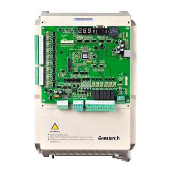
Page 25: Product Appearance
NICE3000 User Manual Product Information Item Specification 5-bit LED display, show parameters of running speed, bus operation panel voltage, etc. 3-bit LED display, displaying the information of main board small keyboard MCB and receiving the simple order input Monitor lift state parameters, including car top control board State monitor and hall call control board. - Page 26 Product Information NICE3000 User Manual Structure Hole Model type (mm) (mm) (mm) (mm) (mm) (mm) (kg) 220-NICE-L-A/B-4018 220-NICE-L-A/B-4022 220-NICE-L-A/B-4030 SIZE-E 541.5 554.5 289.6 14.5 NICE-L-A/B-4018 NICE-L-A/B-4022 NICE-L-A/B-4030 Note: products with other power rank, such as higher than 37kw, due to little usage, we don’t list here.
-
Page 27: Daily Maintenance Of Controller
NICE3000 User Manual Product Information 2.5 Daily Maintenance of Controller Since the influence of ambient temperature, humidity, dust, and vibration, the components in controller may become aging and wearing, which will give rise to the occurrence of potential faults and reduce the life of controller. Therefore, it is quite necessary to do the work of daily maintenance of controller. - Page 28 Product Information NICE3000 User Manual Replacement of aging Parts The wearing parts of controller mainly include the cooling fan and filtering electrolytic capacitor. Their lifetime is closely related to the operating environment and maintenance. General lifetime as follows: Component Lifetime 2 ~ 3 years Electrolytic capacitor 4 ~ 5 years...
- Page 29 Structure of the control system and the component introduction...
-
Page 30: Chapter 3 Structure Of The Control System And The Component Introduction
3.1 Using Introduction of CTB Car top board MCTC-CTB-A is the main control board of NICE 3000’s car . It is made up of eight digital signal input terminals, one analog voltage signal input terminal, eight relay N.O. - Page 31 NICE3000 User Manual Structure of the control system and the component introduction Fig 3-2 Definition of CTB terminals Explanation of controlling terminals’ function Terminal Type Terminal name Functional explanation designation Connect to +24V external power (CN1、CN2 source Provide+24Vpower for whole terminals) board as Operational Power Supply...
- Page 32 Structure of the control system and the component introduction NICE3000 User Manual Terminal Type Terminal name Functional explanation designation AC:250V,3ª A-AM Car fan / illuminate controller Or DC:30V,1A B1-BM Front Door opening signal B2-BM Front Door closing signal Door lock (Closed indicates the B3-BM door lock is smooth) C1-CM...
-
Page 33: Using Introduction Of Ccb
Structure of the control system and the component introduction 3.2 Using introduction of CCB Command board CCB is matched with car top board CTB in NICE 3000 integrated controller. Each command board comprises 24 input interfaces and 22 output interfaces, including 16 floor buttons and 8 functional signals. - Page 34 Structure of the control system and the component introduction NICE3000 User Manual 3.2.2 Introduction of installation and using Installation mode Install in the condition of power off; Aim at four installing pores of car, and then use screwdriver to hold; After checking the order of button connection and button plug, plug button switch into instruction plate’s slot;...
- Page 35 NICE3000 User Manual Structure of the control system and the component introduction When use these three command boards, users must pay attention to the wiring and the use of buttons between MP24 and GND. Do not jump-out or it will damage the command board. Command board’s 4 PIN interface‘s definition of VER-C edition is shown in the following chart 9-6: KEY-...
- Page 36 Structure of the control system and the component introduction NICE3000 User Manual Sequence Corresponding Definition Instruction number(n) interface JP17 Door opening button input JP18 Door closed button input JP19 Door opening delay button input JP20 Nonstop button input Invalid for command board 2 JP21 Motorman button input JP22...
-
Page 37: Direction For Use Of Hcb
MCTC-HCB-H, MCTC-HCB-F, and MCTC-HCB-J. 3.3.1 MCTC-HCB-B The hall call board HCB is one of the main interfaces between the NICE 3000 controller and users in order to meet the needs of different customers and enrich the product range, we develop the non-display hall call board –... - Page 38 Structure of the control system and the component introduction NICE3000 User Manual 3.3.1.2 Appearance and measurement 70.2mm C1 C2 C3 C4 C5 C6 B2 B1 TEST IMPE 89S52 56.2mm Fig 3-8 Installation measurement of MCTC-HCB-B 3.3.1.3 Installation and using introduction Dial-code setting F5--- floor 5 TEST--- testing dial-code...
- Page 39 NICE3000 User Manual Structure of the control system and the component introduction S1.1~S1.5 S2.1 S2.2 S2.3 S2.4 S2.5 MOD bus 7 segment Floor address Floor address terminal matching OFF Detection code function setting,range:0~31 setting resistance setting S1.1~S1.3floor MOD-bus Voice station setting terminal matching Detection...
- Page 40 Structure of the control system and the component introduction NICE3000 User Manual 5th floor, successively set as 7,8,9..., and if there is no plate in the 3rd and 4th floors, from the 5th floor, successively set as 5,6,7..Input part ...
- Page 41 NICE3000 User Manual Structure of the control system and the component introduction The no-display hall call board designed with 4 relay output, namely the K1、K2、K3 and K4, output by CN2 terminal. Please refer to the fig 3-9-3 for details HPB、LCD function Realization of HPB and LCD function The dial switch bit definitions see Table 1 ...
- Page 42 Structure of the control system and the component introduction NICE3000 User Manual The open collector output as the Table 3 3.3.2 MCTC-HCB-D1 MCTC-HCB-D1 is designed on the basis of our company’s general dot-matrix, it’s adopts the LCD segment display mode to display the up/down indicate arrows, floor signals and elevator errors, over-load, inspection, fire-emergency 4 states.
- Page 43 Structure of the control system and the component introduction Name designation and model CTC is the short name of Suzhou Monarch Control Technology Co., Ltd, the HCB is the hall, car display communication board, D means the segment LCD display, 1 means that this is the fi rst kind of segment LCD hall call board, more display board of this series will be added follow-up.
- Page 44 Structure of the control system and the component introduction NICE3000 User Manual Terminal Function Interface of down call button, 2、3 are the input switch value wiring pin,1、4 are the power wiring pin,used to control button light Mod-bus communication and power wire terminal,4PIN interface,2、3 are Mod- bus communication wire pin,1、4 are power wiring pin.
- Page 45 NICE3000 User Manual Structure of the control system and the component introduction If the floor information setting is 0, it is car display panel; The floor address is valid floor number (based on the leveling plate), increasing from the bottom to the top and not related to the actual floor number.
- Page 46 Structure of the control system and the component introduction NICE3000 User Manual Instruction of plugs Plug Name Function Definition Setting of matched resistance to the terminal of MOD main line Testing terminal, setting as “OFF” in application J1 setting: Set the matched resistance to the terminal according to the actual needs. Generally it’s only needed to set the J1 plug with the floor address 1 as “ON”.
- Page 47 NICE3000 User Manual Structure of the control system and the component introduction Direction for installation and using The floor addresses setting and installation mode, input and output definition, and plug definition are all the same with MCTC-HCB-F; there are only V1, V2 and V3 three dot-matrixes in the dot-matrix displaying of MCTC-HCB-H, without V4 comparing with MCTC-HCB-F.
- Page 48 Structure of the control system and the component introduction NICE3000 User Manual Size R2.5mm 70mm MCTC-HCB-I 56mm Fig 3-17 MCTC-HCB-I install size Function introduction This is the slim type design of MCTC-HCB-H, and with the same function as MCTC-HCB-H. The high light red dot-matrix, a 5*7 dot-matrix display the run direction, two 5*7 dot-matrix display the high and low bit of floor information respectively.
- Page 49 NICE3000 User Manual Structure of the control system and the component introduction Floor address settings: Button stroe, there is storing buttons on the board. Power supply and communication input terminal (CN1): White, horizontal blocks with 3.96 gap distance, user need to prepare the terminal head. M OD- M OD+ M P24...
- Page 50 Structure of the control system and the component introduction NICE3000 User Manual Size 146*70*10(mm) Fig 3-186 MCTC-HCB-N install size Function specification Identify the floor storing by a jumper J1, When the J1 is short circuit, the call buttons JP2 and JP3 were changed to be the AS buttons which used to modify the store floor;...
- Page 51 NICE3000 User Manual Structure of the control system and the component introduction call button is 4PIN,examine form the front, from left to right is: Name Meaning Button switch Button switch Button light Button light Power supply communication terminal is 6PIN,examine from the front, from left to the right is: Name Meaning None...
- Page 52 Structure of the control system and the component introduction NICE3000 User Manual Product Photo Fig 3-19 MCTC-HCB-K photo Size Fig 3-20 MCTC-HCB-K install size...
-
Page 53: Sort Of Adjusting Tools For Nice 3000
M P24 Fig 3-21 power supply communication interface (CN2)definition 3.4 Sort of adjusting tools for NICE 3000 Adjusting tools of NICE3000 include four kinds: operation control and information display panel (operation panel for short), small keyboard on MCB, upper monitor motoring software of NICE 3000, and PDA monitoring software. - Page 54 Structure of the control system and the component introduction NICE3000 User Manual Instruction of buttons on the operation panel keyboard: name function Program key Enter or exit the primary menu and delete quick menu ENTER Confirm Enter the menu level by level and confirm setting parameter Increase of date and function code ∧...
- Page 55 NICE3000 User Manual Structure of the control system and the component introduction In the third level menu, if the parameter has no flash bit, it means the function code cannot be changed and the possible reasons are: This parameter of this function code cannot be changed, such as the actually detected parameter and running record parameter.
- Page 56 Up to 16 parameters can be saved in quick menu. If 16 parameters are stored and more are wanted, the “FULL” will be displayed; if entering the menu and the “NULL” is displayed, which means no parameter is stored in the quick menu. There are 16 parameters stored in advance in NICE 3000: F0-03: Maximum running speed F5-36:...
- Page 57 NICE3000 User Manual Structure of the control system and the component introduction delete F5-36, please operate as follows: Flash display QUICK 0.000 uF0.03 uF3.10 uF5.36 uF5.36 ENTER Date display QUICK 0.000 uF8.11 Fig 3-29 Delete the parameter in the quick menu Press PRG in the quick menu, the displayed parameter flashes, and prompt the user whether to delete the parameter in the menu.
- Page 58 Structure of the control system and the component introduction NICE3000 User Manual 3.4.8 Appearance of Small Keyboard Appearance is as follows: Fig 3-31 3.4.9 Function Instruction of Small Keyboard 3 keys are defined as PRG、UP、SET, and marked beside. PRG: In any state, press PRG, the function code will be displayed and it can be changed by pressing UP;...
- Page 59 NICE3000 User Manual Structure of the control system and the component introduction 3.4.11 Function Instruction of Each Menu F0 (Floor and run direction information): F0 date menu will be display as default after electrify. The first bit of numeral lamp is used for direction; the second and the third bit are used for displaying current floor.
-
Page 60: Advanced Door-Open Module(Scb
3.5 Advanced door-open module(SCB) General introduction MCTC-SCB-A is one of the matching accessories of NICE 3000 elevator integrated controller system. In accordance with the various customer needs and expansion of our product range, we developed the Advance door-open module MCTC-SCB-A. - Page 61 NICE3000 User Manual Structure of the control system and the component introduction Logic sequence The time sequence diagram of the advanced door-open module shows the relations between relays and signals, the high electric level indicates the signal is valid. Fig 3-33 Time sequence diagram When apply power, according to the wiring diagram, the relay KM1 will operate, and the relevant contact will activate;...
- Page 62 FL2, and they are all N.O settings, if the on-site sensor is N.C. setting, please use the middle relay to switch to N.O inputting. When the elevator up run, detect the up leveling signal, FL1 and FL2 signals, and processed by the NICE 3000 system to realize the advanced door- opening; same for the down running.
-
Page 63: Voice Landing Report (Chm)
Structure of the control system and the component introduction signal. Disposal method: the X1 and X3 that the leveling signal connect to the NICE 3000 control system, break the door area signal and the X2, and connect the door area signal to the FL1 and FL2, that means connect both FL1 and FL2 to door area signal. -
Page 64: Weighing Sensor (Ldb)
Structure of the control system and the component introduction NICE3000 User Manual Parameter configure process: (default to enter the run mode after the power applied and ringing for 3 times, user can operate setting) First, press FUN key, the reporter will prompt function 1—“reporter language select” Then set the parameters by pressing “+”... - Page 65 NICE3000 User Manual Structure of the control system and the component introduction Technical parameters of weighing sensor Diameter 24mm size Height 87mm Users can choose to equip weighing board (MCTC-LDB-A) for providing the system with the signals of light load, full -load and over-load and complete to compensate analog weight, in order to improve stability of lift running.
- Page 66 Structure of the control system and the component introduction NICE3000 User Manual Attention items: The installation position should be close to the middle of the car cage as possible as it can. The square porcelain steel with pasted paper is the working surface, and it should be opposite to the transducer.
-
Page 67: Ie Module Applied To The Elevator Faults Conditions The Mctc-Ie-A
NICE3000 User Manual Structure of the control system and the component introduction 3.8 IE module Applied to the elevator faults conditions the MCTC-IE-A MCTC-IE-A –GSM message module is applied to the elevator faults condition, the MCTC-IE-A board collects the error information and sends a prompt message to the fixed cell-phone to remind the elevator maintaining technician about the error condition, and ensure the prompt maintaining of the elevator. -
Page 68: Other Optional Components
15m, 30m, 50m, and 100m. 3.9.2 Others To coordinate with the use of NICE 3000 system, Suzhou Monarch Control Technology Corp., Ltd. provides other accessories such as group control board (MCTC-GCB-A), short message control board (MCTC-IE-A), PDA adjusting machine (MCTC-PDA-A), Serial transferring to parallel control board (MCTC-HPB-A), residential community monitoring interface board (MCTC-BMS-A) and etc. - Page 69 Installation and wiring...
-
Page 70: Chapter 4 Installation And Wiring
4.1 System Configure Introduction Fig 4-1 System Configure Diagram 4.2 Mechanical Installation NICE 3000 controller installation size requirements: Fig 4-2 controller installation size requirements The unit in the chart is mm. A shall be bigger than 50mm for the controller of 22kW or above. -
Page 71: Electric Installation And Wiring
NICE-L-A/B-4037 NICE-L-A/B-4045 The following types of NICE 3000 integrated controller have been equipped with brake unit inside with power no more than 30KW. User just needs to externally connect brake resistance. For those types above 30KW, it needs brake unit and brake resistance. - Page 72 Installation and wiring NICE3000 User Manual Type Configure of brake resistance Brake unit MCTC- DBR-4001 300W ,200Ω MCTC- DBR-4002 600W ,220Ω MCTC- DBR-4003 1100W ,130Ω MCTC- DBR-4005 1600W ,90Ω MCTC- DBR-4007 2500W ,65Ω Standard equipment MCTC- DBR-4011 3500W ,43Ω MCTC- DBR-4015 4500W ,32Ω...
- Page 73 NICE3000 User Manual Installation and wiring Terminal Name Instruction For controller below 30kW(include 30kW) they are P(+)、PB Terminals for brake resistor for brake unit U、V、W controller output terminal Connect 3-phase motor Terminal for grounding Grounding terminal Note: Select the recommended resistor according to selection form of brake resistance’s type. ...
- Page 74 Installation and wiring NICE3000 User Manual Terminal Name Instruction CTB communication when communication well between MCB and indicator CTB, COP indicator lighten (green) when communication well between MCB and Hall call indicator HCB, HOP indicator lighten (green) MODBUS Parallel indicator The parallel communication is normal (green) X1~X24 Input signal indicator...
- Page 75 NICE3000 User Manual Installation and wiring Terminal Name Instruction simulate input terminal terminal for simulation input,-10~10V,for weighing device DC 0V power Plug CN3 instruction: Terminal Name Instruction Provide MCTC-MCB-A with DC24V, for input, output External DC24V input circuit and communication circuit Modbus communication MOD+ Display control board Seriall communication signal...
- Page 76 Installation and wiring NICE3000 User Manual jumper J5、J6 instruction (Except for VER A, VER B, VER C) Terminal Name Instruction Short J5, inner calling communication circuit will be connected with internal resistance CAN communication matching resistance jumper Outer calling matching resistance jumper Short J6, outer calling communication circuit will be connected with internal resistance.
- Page 77 NICE3000 User Manual Installation and wiring Encoder wiring Following items should be noticed in encoder wiring: PG wire should be laid separately and keep distance from control circuit and driver circuit and forbidden to parallel with them. PG wire should be shield wire, and shield layer should connect to PE near controller. (In ...
- Page 78 Installation and wiring NICE3000 User Manual Connect to the bottom layer of the control 接至底层驱动板 board OUT-A OUT-B Chart 4-8 MCTC-PG-B sketch MCTC-PG-B technique data Responding Output Output Frequency Function speed impedance current division range Encoder power VCC,GND About 300Ω 300mA supply A+,B+,...
- Page 79 NICE3000 User Manual Installation and wiring MCTC-PG-E Fig 4-10 MCTC-PG-E appearance and size MCTC-PG-E wiring instruction The CN1 terminal of MCTC-PG-E is connected with SIN/COS encoder with Type D 15 pins (DB15) connector. The meaning of each pin of the connector is as follows: Type of PG trans- The meaning of DB15’s each pin Suitable encoder...
- Page 80 Installation and wiring NICE3000 User Manual...
- Page 81 Function parameters tables...
-
Page 82: Chapter 5 Function Parameters Tables
Function parameters tables NICE3000 User Manual Chapter 5 Function parameters tables 5.1 Function parameters Indication Its function parameters are classified into 17 groups. Each function group has several function codes. The function code adopts the 3 level menu in the form of F X-XX. In the manual it means No. -
Page 83: Function Parameters Tables
NICE3000 User Manual Function parameters tables 5.2 Function Parameters Tables 5.2.1 Groups of Function Parameters Press UP/DOWN button after pressing “PRG”, all the first level menu displayed are the groups of function. Details as follows: F0——Basic parameters F9——Time parameters F1——Motor parameters FA——Keyboard setting parameters F2——Vector control parameters FB——Door function parameters... - Page 84 Function parameters tables NICE3000 User Manual Modifi- Function Name Setting Range Min. Unit Default Code cation Stator resistance (Asynchronous motor) Depending 0.000~30.000Ω 0.001Ω F1-06 Encoder original on the ☆ 0~359.9° 0.1° angle model (Synchronous motor) Rotor Depending resistance 0.000~30.000Ω 0.001Ω F1-07 on the ☆...
- Page 85 NICE3000 User Manual Function parameters tables Modifi- Function Name Setting Range Min. Unit Default Code cation 0:same direction 1:reverse running direction, reverse position impulse direction Lift Running F2-10 2:same running direction, reverse impulse ☆ direction direction 3:reverse running direction, same impulse direction F3 Running Control Parameters F3-00...
- Page 86 Function parameters tables NICE3000 User Manual Modifi- Function Name Setting Range Min. Unit Default Code cation F3-20 Time-lag of end 0.000~1.000s 0.001s 0.300s ★ running F4 Floor Position Parameters Leveling F4-00 0~60mm 30mm ★ adjusting F4-01 Current floor F6-01~F6-00 ★ High bit of F4-02 0~65535...
- Page 87 NICE3000 User Manual Function parameters tables Modifi- Function Name Setting Range Min. Unit Default Code cation F4-26 High bit of floor 0~65535 ★ high 11 F4-27 Low bit of floor 0~65535 ★ high 11 F4-28 High bit of floor 0~65535 ★...
- Page 88 Function parameters tables NICE3000 User Manual Modifi- Function Name Setting Range Min. Unit Default Code cation F4-53 Low bit of floor 0~65535 ★ high 24 F4-54 High bit of floor 0~65535 ★ high 25 F4-55 Low bit of floor 0~65535 ★...
- Page 89 NICE3000 User Manual Function parameters tables Modifi- Function Name Setting Range Min. Unit Default Code cation 00:No function F5-01 Select function 01:N.O. input of up leveling ★ of terminal X1 02:N.O. input of down leveling 03:N.O. input of door zone F5-02 Select function 04:N.O.
- Page 90 Function parameters tables NICE3000 User Manual Modifi- Function Name Setting Range Min. Unit Default Code cation Car top board F5-25 input type 0~255 ★ selection F5-26 Select function 0:No function ★ of terminal Y1 1:Run contactor output 2:Brake contactor output F5-27 Select function 3:advanced door-opening module output ★...
- Page 91 NICE3000 User Manual Function parameters tables Modifi- Function Name Setting Range Min. Unit Default Code cation Bit0:separate stay function Parallel F6-09 Bit1: reserved ★ selection Bit2:Parallel in monitor contactor F6-10 Leveling sensor 10~50ms 14ms ★ delay time Bit4: stop 300 ms current bias mode Bit5:synchronous motor startup current detect function Elevator...
- Page 92 Function parameters tables NICE3000 User Manual Modifi- Function Name Setting Range Min. Unit Default Code cation F7-01 Test floor 2 0~the highest floor (F6-00) ☆ F7-02 Test floor 3 0~the highest floor (F6-00) ☆ Test times at F7-03 0~60000 ☆ random Landing call 0:Landing call allowable;...
- Page 93 NICE3000 User Manual Function parameters tables Modifi- Function Name Setting Range Min. Unit Default Code cation Current F9-04 Clock: month 1~12 ☆ time Current F9-05 Clock: day 1~31 ☆ time Current F9-06 Clock: hour 0~23 ☆ time Current F9-07 Clock: minute 0~59 ☆...
- Page 94 Function parameters tables NICE3000 User Manual Modifi- Function Name Setting Range Min. Unit Default Code cation Door open/ FB-09 0~20 ☆ close times Run main 0: open the door normally FB-10 landing door 1: waiting for opening the door state Time keeping FB-11 for hall call door...
- Page 95 NICE3000 User Manual Function parameters tables Modifi- Function Name Setting Range Min. Unit Default Code cation 0~3199 Note: The first two figures mean the floor’s number, and the last two mean the error code. e.g. error 30 occurs in Floor1(the elevator’s position is abnormal), the error information displays 0130.
- Page 96 Function parameters tables NICE3000 User Manual Modifi- Function Name Setting Range Min. Unit Default Code cation FC-10 The third error 0~3199 ● information The third error FC-11 month and day 0~1231 ● FC-12 The fourth error 0~3199 ● information FC-13 The fourth error month and day 0~1231 ●...
- Page 97 NICE3000 User Manual Function parameters tables Modifi- Function Name Setting Range Min. Unit Default Code cation 0: No check-out: Data format<8,N,2> FD-01 Data format 1: Even check-out: Data format<8,E,1> ★ 2: Odd check-out: Data format<8,0,1> FD-02 Local address 0~127,0:Broadcasting address ★...
- Page 98 Function parameters tables NICE3000 User Manual Modifi- Function Name Setting Range Min. Unit Default Code cation FE-01 Hall display of 1901 ☆ floor 1 FE-02 Hall display of 1902 ☆ floor 2 FE-03 Hall display of 1903 ☆ floor 3 FE-04 Hall display of 1904 ☆...
- Page 99 NICE3000 User Manual Function parameters tables Modifi- Function Name Setting Range Min. Unit Default Code cation 0~65535 Lift factory FE-32 function Selected by bit, the function is valid if the bit is 35843 ★ selection1 1, details referring to chapter 6. Lift factory Selected by bit, the function is valid if the bit is FE-33...
- Page 100 Function parameters tables NICE3000 User Manual...
- Page 101 Function parameter description...
-
Page 102: Chapter 6 Function Parameter Description
Function parameter description NICE3000 User Manual Chapter 6 Function parameter description 6.1 F0 Group Basic Function Group Control mode Default Min. Unit F0-00 Setting Range 0、1 Select the control mode of the system. 0:Open-loop vector. Speed sensorless vector control. It is mainly applicable for low speed running in adjusting and fault judging in maintaining of asynchronous motor. -
Page 103: F1 Group Motor Parameters
NICE3000 User Manual Function parameter description and motor of the lift. The parameter F0-03 means the actual speed within the speed range of F0-04. For example: One lift rated speed is 1.750 m/s, but the actual Max.speed is 1.720 m/s. So F0-03 = 1.720 m/s;... - Page 104 Function parameter description NICE3000 User Manual Function Name Default Min. Unit Setting Range code Depending on F1-01 Rated power 0.1kW 1.1~75.0kW the model F1-02 Rated voltage 380V 0~440V Depending on F1-03 Rated current 0.01A 0.00~655.00A the model F1-04 Rated frequency 50.00Hz 0.01Hz 0.00~99.00Hz...
- Page 105 After modifying the asynchronous motor’s rated power F1-01, the parameter values in F1-06 to F1-10 will automatically recover to the default standard motor parameters. When NICE3000 is used for permanent-magnet synchronous motor: NICE 3000 can gain parameters F1-06, F1-08 through with-load tuning and no-load tuning. After modifying the rated power F1-01, the parameter values in F1-06 to F1-10 will not automatically recover.
- Page 106 Function parameter description NICE3000 User Manual First, set F0-01 as 0: the control mode selection is the operating panel command channel. Set F1-00 as 0 by actual motor types: asynchronous motor. Then set F1-01、F1-02、F1-03、 F1-04、F1-05 according to the nameplate parameters of motor. If the motor can be separated from load, the parameter F1-11 selects 2(motor no-load tuning).
- Page 107 NICE3000 User Manual Function parameter description F0-01=0 Set as operation panel control F1-01、F1-02、F1-03、F1-04、F1-05 set according to the nameplate parameters of the motor F0-01=0 Operating panel command channel F1-11=1or2 (1:Static tuning . 2:Complete tuning , must separate the load from motor) note:thedisplay TUNE that is flashing ,make sure the output circuit is looped,Then press the RUN button to perform the parameter tuning .
- Page 108 Function parameter description NICE3000 User Manual After tuning, set F0-02=0.5 m/s, and press RUN .Check if the motor running is right or not. If motor isn’t running right, please repeat step 1, 2, 3 after transposing direction of encode signal. F0-01=0(No load tunning) Recover the setting parameter of terminal running Or (with load tuning )
- Page 109 Whether the traction machine’s forward and reversal running are stable and no noise; because of no load in the traction machine, the current will be extremely small and NICE 3000 displays the current lower than 1A. After the confirmation of the two points, NICE 3000 have recorded the traction machine’s encoder position correctly into F1-06 (Users can record it down for the later using), and it can do the normal control.
-
Page 110: F2 Group Vector Control Parameters
Function parameter description NICE3000 User Manual It can set the pulse number of each rotation of the encoder, according to the nameplate of encode. Note: it must set the encoder pulse number correctly when it’s in the closed loop vector control. - Page 111 NICE3000 User Manual Function parameter description Fig 6-3 PI Parameters Schematic Diagram It can regulate the speed dynamic response characteristic of the vector control by setting the proportional coefficient and integrating time of the speed regulator. It can accelerate the dynamic response of the speed loop by increasing the proportional gain or decreasing the integrating time.
-
Page 112: F3 Group Running Control Parameters
Function parameter description NICE3000 User Manual Running direction Default Min. Unit F2-10 Setting Range l0、1 0: The same direction 1: The running direction choose reversal, position pulse direction choose reversal 2: The same running direction, position pulse direction choose reversal 3: The running direction choose reversal, position pulse direction choose the same In this function code, it can choose reversal of running direction (Motor’s running direction when the connection of motor didn’t change), and position signal (Means F4-03 used for... - Page 113 NICE3000 User Manual Function parameter description Deceleration Default 0.600m/s Min. Unit 0.001m/s F3-05 Setting Range 0.200~2.000m/s Inflexion slow-down time 1 Default 2.500s Min. Unit 0.001s F3-06 Setting Range 0.300~4.000s Inflexion slow-down time 2 Default 2.500s Min. Unit 0.001s F3-07 Setting Range 0.300~4.l000s The three function codes decide the S curve parameters of lift slow-down running: F3-05 is deceleration of S curve of lift slow-down running.
- Page 114 Function parameter description NICE3000 User Manual It means the re-leveling speed when the lift is in the door zone. Because the length of leveling plate is different in different system, the parameter adjusting can assure the landing accuracy of re-leveling. It is used when chooses the re-leveling function through FE-32.. Low-speed running Default 0.250m/s...
- Page 115 NICE3000 User Manual Function parameter description NO. 1 force NO. 2 force NO. 3 force Switch reducer reducer reducer ≤1.5m/s 1.5m Distance 2.0m/s>v>1.5m/s 1.5m 3.5m ≥2.0m/s 1.5m 3.5m S means the setting distance of switch of forced reducer to leveling position. The distance S must be enough for the deceleration from F3-08 to 0.
-
Page 116: F4 Group Position Parameters
Function parameter description NICE3000 User Manual Fig 6-5 Running time sequence chart 6.5 F4 Group Position Parameters Leveling adjusting Default 30mm Min. Unit F4-00 Setting Range 0~60mm It ensures the landing accuracy of lift. If the position of leveling inductor isn’t in the middle of inductor plate when the lift stops, adjust this parameter. -
Page 117: F5 Group Terminal Function Parameters
NICE3000 User Manual Function parameter description Function code Name Default Min. Unit Setting Range F4-05 Low bit of leveling plate 0~65535 It can show the pulse number of leveling plate’s practical length. It is noted when auto-tuning in shaft. Users can adjust it according to practical status. Function code Name Default... - Page 118 Function parameter description NICE3000 User Manual X1~X24 is switch input terminal, and they can select corresponding function codes 00~ 61.The same function code can’t be used repeatedly. If the terminal X1 input signal is 24V, the signal light X1 of the main operation panel will light. The rest may be deduced by analogy. The code of every function is as follows: 00:No function The controller does not work even if the signal is inputted.
- Page 119 21:N.O. input of NO. 3 down force reducer These functional codes set input point into N.O. input of force reducer, corresponding to the force reducer switch signal. NICE 3000 system records these positions of switches into parameters of F3 group.
- Page 120 Function parameter description NICE3000 User Manual It adds the second safety circuit inputting point in order to protect against the accidents caused by the pick-up of the safety circuit feedback contactor. If both input points are selected NICE3000 system certificates the normal work of the safety circuit only when both are valid. Otherwise, the system will be in E4 indication.
- Page 121 NICE3000 User Manual Function parameter description Function code Name Default Min. Unit Setting Range F5-30 Y5 function selection 0~16 F5-31 Y6 function selection 0~16 The system output is relay output. There are function items 0~16: 0:No function: Output terminal hasn’t any function. 1:Run contactor output: The system outputs the pick-up command of run contactor;...
- Page 122 Function parameter description NICE3000 User Manual 11:Run monitor: NICE 3000 is in running state. 12:Synchronous motor auto-run: It’s the self-locking contactor to control permanent-magnet synchronous motor. If the synchronous motor is in self-running emergency when the lift is in power failure emergency running state, the brake open, the corresponding terminal output, lift slip into the nearest leveling land and open door.
- Page 123 NICE3000 User Manual Function parameter description Tube Tube Serial passage Meaning of tube passage “light” Meaning of tube passage “No light” number marker Hall call communication of address hall call communication of address dial-up 1 normal dial-up 1 deviant Outside call communication of Outside call communication of address dial-up 2 normal address dial-up 2 deviant...
- Page 124 Function parameter description NICE3000 User Manual Tube Tube Serial passage Meaning of tube passage “light” Meaning of tube passage “No light” number marker Outside call communication of Outside call communication of address dial-up 17 normal address dial-up 17 deviant Outside call communication of Outside call communication of address dial-up 18 normal address dial-up 18 deviant...
- Page 125 NICE3000 User Manual Function parameter description Add 1 time doo-lock break when Bit 6 Bit 7 No error display on the small keypad the inspction to normal Canccel the door-open order immdiate after the door-open limit Elevator stop when the feedback is Bit 8 Bit 9 abnormal...
- Page 126 Function parameter description NICE3000 User Manual Tube Serial Tube passage Tube passage meaning Tube passage “light” meaning number marker Inspection signal Inspection signal availability Inspection up signal Inspection up signal availability Inspection down signal Inspection down signal availability Fire signal Fire signal availability Up end signal availability, at Up end signal...
- Page 127 NICE3000 User Manual Function parameter description F5-34 expresses the state of the car top panel input or output terminal. Its meanings are listed in the following charts: Tube Serial Tube passage Tube passage meaning Tube passage “light” meaning number marker Front light curtain input Light curtain shut out Back light curtain input...
-
Page 128: F6 Group Lift Basic Parameters
Function parameter description NICE3000 User Manual Tube Serial Tube passage Tube passage meaning Tube passage “light” meaning number marker Door-open display output Door-open display light Door-close display output Door-close display light Door-open delay display Door-open delay display light output Non-stop display output Non-stop display light Reserved Buzzer output... - Page 129 NICE3000 User Manual Function parameter description The lift will return to the landing when the system is in fire landing state. Stop landing Default Min. Unit F6-04 Setting Range The lowest landing(F6-01)~The highest landing(F6-00) When lift is in stopping state, it will return to this landing after completing control box command. Function code Name Default...
- Page 130 Function parameter description NICE3000 User Manual Lift number Default Min. Unit F6-08 Setting Range 1~8 It can set lift number when using group control. When F6-07 = 1, this function is useless. 1:Lift 1.At this time, the car top panel default is lift 1 which means the first three are set as OFF.
-
Page 131: F7 Group Testing Function Parameters
NICE3000 User Manual Function parameter description Function code Name Default Min. Unit Setting Range Time-sharing service 1 F6-20 65535 0~65535 floor 1 Time-sharing service 1 F6-21 65535 0~65535 floor 2 Time-sharing service 2 F6-22 00:00 00:01 00:00~23:59 start time Time-sharing service 2 F6-23 00:00 00:01... - Page 132 0 instead. NICE 3000 can run at random. There are 5s in each running interval when simulating the daily running state. The times set by F7-03 are generated by the times of target floors occur at random.
-
Page 133: F8 Group Reinforce Function Parameters
NICE3000 User Manual Function parameter description 6.9 F8 Group Reinforce Function Parameters Weighing auto-tuning Default Min. Unit F8-00 Setting Range 0~100% It means the weighing auto-tuning setting. There are three steps of the weighing auto-tuning: 1、Ensure F8-01 setting is 0 and F5-36 choose 2 or 3. This means that the system allow the weighing auto- tuning. - Page 134 Function parameter description NICE3000 User Manual the larger the gain will be in the same condition. The controller can identify the driving and brake state according to the signals of weight conductor, and then work out desirable torque compensation values. When the system uses analog weighing, these group parameters are used for adjusting starting.
-
Page 135: F9 Group Time Parameters
F8-10 0: Motor isn’t running Setting Range 1: UPS power running 2: 48V batter power NICE 3000 supplies three ways of emergency rescue methods, details are in chapter 7. 0.200(asynchronous) Min. Car stopping torque output delay Default 0.001 0.600(sync) -
Page 136: Fa Group Keyboard Setting Parameters
Function parameter description NICE3000 User Manual Those parameters mentioned above are the interior time of NICE3000.This clock can count time when there’s power failure.Nice3000 can complete many special functions with time by this clock such as fastigium service, etc. So users should set this parameter right by actual time when first electrify. - Page 137 NICE3000 User Manual Function parameter description Display or Binary bit Display or Binary bit Binary bit Parameter Binary bit Parameter setting setting Output Car top Bit4 Display Bit12 current input state display Car top Output Bit5 Display Bit13 output frequency display state Input...
- Page 138 Function parameter description NICE3000 User Manual Input terminal low bit: It shows the meaning of the terminals by bit. If the bit is “1”, the signal is valid. There is 16 bit whose meanings are as follows: Binary bit Meaning Binary bit Meaning Bit0...
- Page 139 NICE3000 User Manual Function parameter description Current station: It reflects the absolute position of the car to the leveling plate of the first floor. The unit is M. Car load: according to the information from the sensor, it’s the percentage of car load to rated load, with the unit %.
-
Page 140: Fb Group Door Function Parameters
Function parameter description NICE3000 User Manual Binary bit Meaning Binary bit Meaning Bit4 Lift state: Bit12 System full load 0: inspection; 1:shaft auto- Bit5 Bit13 System over load tuning; 3:fire arrival main floor; Bit6 Bit14 Reserved 4:firemen; 6:motorman ; 7:normal Bit7 Bit15 Reserved... - Page 141 NICE3000 User Manual Function parameter description Front door service floor 2 Default 65535 Min. Unit FB-03 Setting Range 0~65535(set 17~31 floor) This function code is made up of binary numbers with 16 emic that control those floors allowing front door to open normally within floor 17 to floor 31. Every floor door is controlled by one binary number.
- Page 142 Function parameter description NICE3000 User Manual Door open/close times Default Min. Unit FB-09 Setting Range 0~20 This function code sets the door open and close times after the FB-06/FB-08 setting time. When lift on-off door times is over this setting value, lift will warn E48 error or E49 error. If FB-09 = 0, door on-off protection is invalidation.
-
Page 143: Fc Group Protection Function Parameters
NICE3000 User Manual Function parameter description 6.13 FC Group Protection Function Parameters Selection of short circuit protection Default Min. Unit detection to the earth after power on FC-00 Setting Range 0、1 It can detect if there’s short circuit error to the earth when power on through the setting of this function code. - Page 144 Function parameter description NICE3000 User Manual Error self-resetting times Default Min. Unit FC-04 Setting Range 0~10 This function code can set the system self-resetting times when there’s system error. If the system error times are over this value, the system will stay and wait for service. 0:It means that there’s no self-resetting function in the system.
-
Page 145: Fd Group Communication Parameters
NICE3000 User Manual Function parameter description 6.14 FD Group Communication Parameters Function code Name Setting Range Default Min. Unit 0:300bps 1:600bps 2:1200bps 3:2400bps FD-00 Baud rate setting 4:4800bps 5:9600bps 6:19200bps 7:38400bps 0: No check-out FD-01 Data format 1: Even check-out 2: Odd check-out 0~127,0:... - Page 146 Function parameter description NICE3000 User Manual Function code Name Setting Range Min. Unit Default FE-01 Floor 1 corresponding display 1901 FE-02 Floor 2 corresponding display 1902 FE-03 Floor 3 corresponding display 1903 FE-04 Floor 4 corresponding display 1904 FE-05 Floor 5 corresponding display 1905 FE-06 Floor 6 corresponding display...
- Page 147 NICE3000 User Manual Function parameter description Code Display Code Display No display ≥22 No display For example: Required Corresponding Actual floor Higher 2 bit setting Lower 2 bit setting displaying function code setting ‘1’ ‘-’ corresponding Basement 1 corresponding code 1801 code 18 No display,...
- Page 148 Function parameter description NICE3000 User Manual Lift factory function selection1 Default 35843 Min. Unit FE-32 Setting Range 0~65535 This function code sets the lift factory required function. Each function is controlled by one binary number,”1” expresses this function allowable,”0” expresses this function forbidden. If lift needs motorman function, fire return function, inspection automatic close, car call miss- delete, door lock jump-out inspection function valid while other function invalidation, the binary system setting is as follows:...
- Page 149 Hall call conglutination disposal: Generally, if the hall call button is conglutination, it may cause the lift repeating opening the door in the current floor. After using this function, Nice 3000 can identify the information of the hall call button automatically. If any abnormal is found, it will disposal the button in self-motion, so it won’t affect the using of the lift.
- Page 150 Function parameter description NICE3000 User Manual Brake output pre-run output For special asynchronous master machine use, special treatment for time sequence; invalid for sync machine. Independent running: It’s not in parallel (group control), and it gets into the independent running condition through the independent running switch in the car cage. At the moment, the lift doesn’t respond to the hall call and the door operation is the same with that in motorman condition, which means there’s no automatic door closing and it opens the door automatically if it fails to complete closing the door.
- Page 151 User can select through BIT12 of FE-33, if the BIT12 is 1, NICE 3000 control system will judge whether the current floor is service floor or not in the course back to the level, and it can only stop at the service floor.
-
Page 152: Fe Group Factory Parameters (Reserved)
Function parameter description NICE3000 User Manual C. External call for current floor opening the door: After the lift close the door, the current floor has the re-opening function. D. Open the door when stops: When the lift stops, it’s judged according to several conditions: If there’s only single side external call, the lift stops and opens the door that is calling;... - Page 153 System typical application and adjustment...
-
Page 154: Chapter 7 System Typical Application And Adjustment
System typical application and adjustment NICE3000 User Manual Chapter 7 System typical application and adjustment 7.1 Lift Adjustment When the lift is in adjusting state, please keep no person in the shaft and in the car! Otherwise, there may be serious accident. In order to be convenient for adjust, this chapter was wrote according to the normal sequence of lift adjustment. - Page 155 NICE3000 User Manual System typical application and adjustment Mechanical parts are installed to the right position, and it won’t cause equipment damages or personal injuries. Encoder inspection Encoder feedback pulse signal is an important assurance for the system to fulfill accurate control.
- Page 156 Motor tuning Motor tuning must be in operation panel control model. Before tuning, please input parameter F1-00~F1-05. NICE 3000 elevator integrated controller matches standard motor parameters according to the nameplate parameter; distance-control mode depends on motor parameter deeply. To gain good control features, the motor parameter inputted must be correct. Details of tuning are described in chapter 6 and the application of synchronous motor in this chapter.
- Page 157 Check input signal: view carefully whether the action sequence of the switch signals received in the travel proceeding is correct or not. Check output signal: view carefully whether the definition of MCB ,NICE 3000 output terminal is correct and work of that is normal, and whether the signal and the contact controlled by MCB output terminal work well.
- Page 158 System typical application and adjustment NICE3000 User Manual Shaft auto-tuning Confirm that safety circuit and door circuit are connected well. Make the system at inspection state. Place the car at lowest floor, and guarantee down force reducer available Set F6-00, F6-01 correctly, and guarantee that F4-01 is 1. After getting into F-7 date menu by switching the mode through the UP and ENTER keyboard on MCB, the data displays “0”.
- Page 159 NICE3000 User Manual System typical application and adjustment Put 100% rated load into the car. Adjust the switch position of full load to make full load switch act but over load switch not. The system memorizes it as full load. Put 110% rated load into the car.
- Page 160 System typical application and adjustment NICE3000 User Manual Adjust for the feeling of comfortable Adjusting the F3 group parameters to make lift run with comfortable feeling. If the lift is wobbling, amend relevant parameters according to curve chart 6-2. Details are described in section 6.4.
-
Page 161: Production Use
NICE3000 User Manual System typical application and adjustment When F8-01=1 viz. Weighing preset torque compensation is used, F8-03 and F8-04 both affect lift starting comfort. If inappropriately adjust these parameters, it can bring shake when starting. The setting value relates with the weighing transducer’s installation position, and the setting value is usually between 0.1~0.4. -
Page 162: Nice3000 Integrated Controller Without Weighing Application Notes
System typical application and adjustment NICE3000 User Manual 7.2.2 Car top board commendatory drawing and relevant parameters setting MCTC-CTB-A lighting source communication CAN+ terminal CAN- car operation panel MCTC-CCB-A Injunction collect board Front door light curtain Back door light curtain MCTC- Front door-open limit HCB-*... -
Page 163: Power Failure Emergency Running Program Instruction
That is a rescue- way’s which the car is running slowly to get to the level. After the Nice 3000 receives a power- failure-rescue signal, you should jump the U, V, W’s wire of permanent-magnet synchronous motor, and open brake. - Page 164 System typical application and adjustment NICE3000 User Manual power to power failure emergency run. After NICE 3000 chooses the way of power failure rescue, it would run by emergency speed, the direction is the same to run direction of lift light- load run.
- Page 165 NICE3000 User Manual System typical application and adjustment UPS power circuit diagram UPC1 DC24V AC220V UPC1 UPC1 UPC1 AC220V AC110V AC220V phase sequence KUP manual/auto NICE3000 SC safe UPC2 UPC2 图1 * UPC2 UPC1 Fig 7-5 Main control board wiring chart AC110V NICE-L-B-40 UPC2...
- Page 166 System typical application and adjustment NICE3000 User Manual 7.4.2 Power failure rescue running instruction Time sequence diagram UPS power AC power Motor speed brake Levelling signal Fig 7-7 Auto-running time sequence Function code setting According to wiring diagram, the NICE3000 auto-running power failure emergency running needs set the following parameter: Setting when Function code...
-
Page 167: Parallel Program Instruction
In parallel, the two lifts are main lift and subordinate lift. When the condition of responding to the external call is totally the same, NICE 3000 system allocates the main lift or the subordinate lift to respond to the call through random function. This can avoid the unbalance use of two elevators. - Page 168 System typical application and adjustment NICE3000 User Manual 7.5.2 Parallel wiring sketch MCTC-MCB- MCTC-MCB- MCTC-CTB- MCTC-CTB- Fig 7-8 Parallel wiring The chart shows the wiring mode of external call button and the wiring mode of parallel CAN communication. When in using, the following items should be paid attention to: Car top board dial setting In parallel, the car top board’s dial switch of the main lift with the number 1 is the same with it’s used in single lift, which means the first bit of Sw1 is on OFF position;...
- Page 169 NICE3000 User Manual System typical application and adjustment function codes need setting: Function code Name Setting Range Setting when parallel F5-29 Y4 function selection 0~14 7.5.3 Parallel lift’s case instruction After the two lifts are in parallel, when the stopping position of the two lifts is different, the lift’s external call dial is different from that of single lift running.
-
Page 170: Instruction Of Group Control Program
Details refer to the instruction of group control 7.7 Instruction of overload and full load In order to facilitate the use of different users, NICE 3000 integrated controller supplies three over load and full load signals inputting mode to fulfill these functions. When in use, correctly set the corresponding parameters to avoid miss-operation. - Page 171 In this way, set F5-36 as 0. 7.7.3 Analog signal inputting mode: There are two inputting passages of the analog signal in NICE 3000 system: CN6 of the car top board (MCTC-CTB-A), CN9 of the main control board (MCTC-MCB-A). If the pre-torque of NICE 3000 uses analog signal inputting, users can take the no load and...
- Page 172 System typical application and adjustment NICE3000 User Manual...
- Page 173 Fault diagnosis and countermeasures...
-
Page 174: Chapter 8 Fault Diagnosis And Countermeasures
The lift integrated controller is a complicated electric control system. Error information produced by NICE 3000 can be divided into 5 sorts according to their influence to the system. Different fault has different disposal mode. And the respective relationship is listed in the next table:... - Page 175 NICE3000 User Manual Fault diagnosis and countermeasures Operate Digital Fault panel tube Fault cause Disposal way Sort description display display 1 .Main loop output is 1 .Obviate exterior grounding or short wiring; problems such as 2 .The connection of connection; traction machine is too 2 .Add reactor or output Invert unit...
- Page 176 Fault diagnosis and countermeasures NICE3000 User Manual Operate Digital Fault panel tube Fault cause Disposal way Sort description display display 1 .Input voltage is too high; 2 .Lift inverse pull is serious; Accelerated 3 .Brake resistance is too Err05 over voltage much, or brake unit is abnormal;...
- Page 177 NICE3000 User Manual Fault diagnosis and countermeasures Operate Digital Fault panel tube Fault cause Disposal way Sort description display display 1 .start position error 2 .torque deviation too big Encoder Err 16 .3 .the feedback speed 1 .check the encoder loop error exceeds 25% of the motor rated speed...
- Page 178 Fault diagnosis and countermeasures NICE3000 User Manual Operate Digital Fault panel tube Fault cause Disposal way Sort description display display check the contactor feedback point (whether it is accord with the main board setting) check the light of main Synchronous board output side is accord motor FX The feedback of...
- Page 179 NICE3000 User Manual Fault diagnosis and countermeasures Operate Digital Fault panel tube Fault cause Disposal way Sort description display display Err 35 occurred before the run contactor pick-up 1 .check whether the 1st down forced deceleration is valid 2 .F4-01=1 3 .whether the inspection switch on the inspection state and able to done the...
- Page 180 Fault diagnosis and countermeasures NICE3000 User Manual Operate Digital Fault panel tube Fault cause Disposal way Sort description display display 1 .Running contactor is not pulled in when the brake is 1 .Detect contactor and open; feedback contact; 2 .When lift continuously 2 .Detect whether the Contact runs over 1 second, the...
- Page 181 NICE3000 User Manual Fault diagnosis and countermeasures Operate Digital Fault panel tube Fault cause Disposal way Sort description display display 1 .check the up limit signal Up limit 2 .check the up limit switch The signal of up limit is cut Err 43 signal off in 3 .if the limit switch is low,...
- Page 182 Fault diagnosis and countermeasures NICE3000 User Manual Operate Digital Fault panel tube Fault cause Disposal way Sort description display display Check the connection of the communication wiring Check the 24V power External call External communication source of lift integrated Err 52 communication with no correct feedback controller...
- Page 183 NOTE: Function Setting Function Setting Function Setting Function Setting code value code value code value code value Date Month Year Location:...
Need help?
Do you have a question about the NICE 3000 and is the answer not in the manual?
Questions and answers
programacion f6 52