Table of Contents
Advertisement
Advertisement
Table of Contents

Related Manuals for MINN KOTA MAXXUM


Summary of Contents for MINN KOTA MAXXUM
- Page 1 MAXXUM ® BOW-MOUNT TROLLING MOTOR USER MANUAL...
- Page 2 REMEMBER TO KEEP YOUR RECEIPT AND IMMEDIATELY REGISTER YOUR TROLLING MOTOR. NOTE: Do not return your Minn Kota motor to your retailer. Your retailer is not authorized to repair or replace this unit. You may obtain service by: calling Minn Kota; returning your motor to the Minn Kota Factory Service Center; sending or taking your motor to any Minn Kota authorized service center.
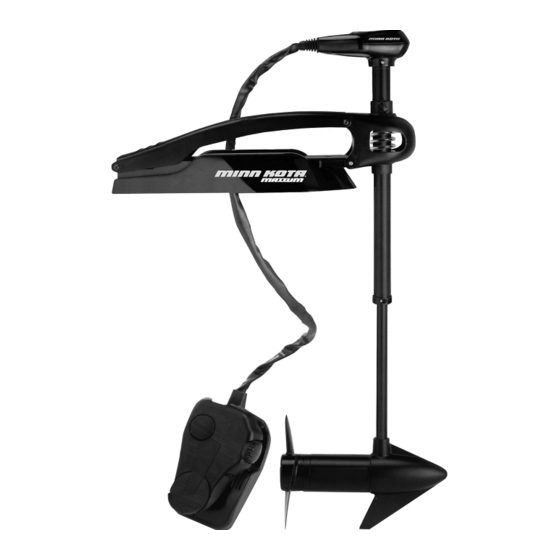
- Page 3 FEATURES Illuminated Directional Indicator Depth Collar Knob BowGuard 360° ® Breakaway Protection Lifetime Warranty Flexible Composite Shaft Momentary On Button Constant On Switch Speed Control Cool Quiet Power Motor Heel Block High-Impact Composite Material Propeller Specifications subject to change without notice. This diagram is for reference only and may differ from your actual motor.
-
Page 4: Mount Installation
MOUNT INSTALLATION TOOLS AND RESOURCES REQUIRED: • (2) 1/2” Wrenches • Standard or Needle Nose Pliers • A second person to help with the installation Upper Pin with Upper Arm Nut and Washer Bow Guard Lower Pin Lower Aluminum Bracket/Arm INSTALLATION OF MOTOR TO MOUNT 1. - Page 5 MOUNT INSTALLATION 3. Open upper arm, rotate and lay over out of the way for lower arm assembly. 4. Align the lower arm and the lower bow guard ears and insert lower pin. 5. Re-install spring clip into lower pin for freshwater models or (E-clip for saltwater motors). 6.
- Page 6 (2 on each side) in the bow plate and drill through with a 9/32” drill bit. Either pattern may be used when installing the motor. - Pattern 1: Minn Kota 3” bolt pattern standard motors. - Pattern 2: Alternate 4” bolt pattern commonly used.
- Page 7 MOUNT INSTALLATION INSTALLING THE BOWMOUNT STABILIZER KIT Tools Needed: • Hand Saw • 3/8” Nut Driver • File or Sandpaper 1. Place the motor in the stowed position. 2. Measure from the screw hole in the upper arm to the boat deck or gunwale. Add 3/4”...
-
Page 8: Battery Wiring & Installation
CAUTION: These guidelines apply to general rigging to support your Minn Kota motor. Powering multiple motors or additional electrical devices from the same power circuit may impact the recommended conductor gauge and circuit breaker size. If you are using wire longer than that provided with your unit, follow the conductor gauge and circuit breaker sizing table below. -
Page 9: Selecting The Correct Batteries
• It is highly recommended that a circuit breaker or fuse be used with this trolling motor. Refer to “Conductor Gauge and Circuit Breaker Sizing Table” in the previous section to fi nd the appropriate circuit breaker or fuse for your motor. For motors requiring a 60-amp breaker, the Minn Kota MKR-19 60-amp circuit breaker is recommended. CONNECTING THE BATTERIES 12 VOLT SYSTEMS: 1. -
Page 10: Motor Wiring Diagram
MOTOR WIRING DIAGRAM NOTE: This is a universal, multi-voltage diagram. Double-check your motor's voltage for proper connections. Over-Current Protection Devices not shown in this illustration. VARIABLE SPEED CONTROL BOARD SPEED ADJUSTMENT SWITCH OPTIONAL BROWN WIRE FOR MOTORS WITH 70 LBS THRUST AND HIGHER. SEE BOAT WIRING DIAGRAM. - Page 11 MOTOR WIRING DIAGRAM NOTE: This is a universal, multi-voltage diagram. Double-check your motor's voltage for proper connections. Over-Current Protection Devices not shown in this illustration. FIVE-SPEED SWITCH INDICATOR LIGHT FIVE SPEED SWITCH WHITE CONNECTING WIRE MOMENTARY SWITCH BLUE CONNECTING WIRE MOM/OFF/ CON SWITCH BLACK –...
-
Page 12: Using And Adjusting The Motor
USING AND ADJUSTING THE MOTOR STOWING AND DEPLOYING THE MOTOR WARNING: When raising or lowering the motor, keep fi ngers clear of all hinge and pivot points and all moving parts. MOUNT FEATURES • The motor mount is designed to fold back and lock the motor fl at on the deck when not in use and to provide secure stowage for transport. -
Page 13: Adjusting The Depth Of The Motor
USING & ADJUSTING THE MOTOR ADJUSTING THE DEPTH OF THE MOTOR Depth Adjustment Knob The propeller tip must be submerged at least 12” to avoid churning Depth Adjustment Knob or agitation of surface water. Outer Shaft 1. With the motor deployed, fi rmly grasp the outer shaft or control Outer Shaft head and hold it steady. -
Page 14: Controlling Speed & Steering With The Foot Pedal
USING & ADJUSTING THE MOTOR CONTROLLING SPEED & STEERING WITH THE FOOT PEDAL Most controls on the foot pedal are easy to operate by either foot or hand: Toe End Speed Knob Momentary On Button Directional Directional Indicator Indicator Heel End Constant On Switch TO ADJUST MOTOR SPEED Turn the speed knob clockwise to increase speed and counter-clockwise to decrease speed. -
Page 15: Service And Maintenance
SERVICE & MAINTENANCE PROPELLER REPLACEMENT TOOLS AND RESOURCES REQUIRED: Propeller • Box End Wrench Slot End - 1/2” for motors with 70 lbs thrust or lower. - 9/16” for motors with 80 lbs thrust or higher. Prop Nut Washer • Screwdriver (optional) CAUTION: Disconnect the motor from the battery before beginning any prop work or... -
Page 16: Troubleshooting And Repair
TROUBLESHOOTING & REPAIR 1. Motor fails to run or lacks power: • Check battery connections for proper polarity. • Make sure terminals are clean and corrosion free. Use fi ne sandpaper or emery cloth to clean terminals. • Check battery water level. Add water if needed. 2. -
Page 17: Parts Diagram
MAXXUM 70 70 LBS THRUST - 24 VOLT - 42” SHAFT This page provides Minn Kota® WEEE compliance disassembly instructions. For more information about where you should dispose of your waste equipment for recycling and recovery and/or your European Union member state require- ments, please contact your dealer or distributor from which your product was purchased. -
Page 18: Parts List
[INCLUDES 39, 43–47, 86,87] 2267800 GEAR- INDICATOR 2263912 MOTOR REST (STD) FW 2372100 SCREW- 8-18 X 5/8 2265514 DECAL- MAXXUM MOTOR REST 2355410 SHRINK TUBE- 3/8 OD X 2” 2261505 SPACER- MOTOR REST 2232360 PULLEY- CABLE DRUM 2773987 BOWPLATE- W/INSERT... - Page 19 ITEM DESCRIPTION NUMBER NUMBER 2223468 SCREW- 8-32 X 7/16 9953104 SCREW-8 X 1/2” (SS) 2262607 PIN- CLEVIS ZP MAXXUM BWGRD 2263455 SCREW- #12-14X1/2 THR FRM 2260805 CLIP- SPRING ZP MAX BG 2265126 BUMPER PAD- FOOT PEDAL 2150400 PULL- GRIP 2266610...
-
Page 20: Compliance Statements
Minn Kota motors are not subject to the disposal regulations EAG-VO (electric devices directive) that implements the WEEE directive. Nevertheless never dispose of your Minn Kota motor in a garbage bin but at the proper place of collection of your local town council. -
Page 21: Recommended Accessories
Stop buying new batteries and start taking care of the ones you’ve got. Many chargers can actually damage your battery over time – creating shorter run times and shorter overall life. Digitally controlled Minn Kota chargers are designed to provide the fastest charge that protect and extend battery life.
Need help?
Do you have a question about the MAXXUM and is the answer not in the manual?
Questions and answers