Table of Contents
Advertisement
Quick Links
Advertisement
Table of Contents

Related Manuals for Simpson 270-5


Summary of Contents for Simpson 270-5
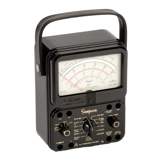
- Page 1 Simpson 270 Series 5 Volt-Ohm-Milliammeter INSTRUCTION MANUAL...
- Page 2 SIMPSON ELECTRIC COMPANY neither assumes nor autho- rizes any other persons to assume for it any other liability in connection with the sales of its products.
-
Page 3: Table Of Contents
Contents 1. INTRODUCTION ................5 General Description ................5 Overload Protection ................5 Internal Batteries .................. 6 Printed Circuit ..................6 Phenolic Case ..................6 Adjust-A-Vue Handle ................6 Test Leads .................... 6 Technical Data ..................6 Definition of Accuracy ................ . 8 1.10 Safety Considerations ................ - Page 4 NOTES...
-
Page 5: Introduction
INTRODUCTION General Description The Simpson Volt-Ohm-Milliammeter 270 Series 5 is a rugged, accurate, com- pact and easy-to-use instrument that will make accurate measurements of AC and DC voltage, direct current, resistance, decibels, and output voltage. The output voltage function is used for measuring the AC component of a mixture of AC and DC voltage. -
Page 6: Internal Batteries
Internal Batteries There are two batteries in the ohmmeter circuits, a NEDA 13F size D cell that furnishes 1.5-volts for the R x 1 and R x 100 ranges and a NEDA 1604 battery that furnishes 9-volts for the R x 10,000 range. Printed Circuit Most of the component parts are mounted on a printed circuit board which simpli- fies assembly and maintenance, thus extending the useful life of the Instrument. - Page 7 4. OUTPUT VOLTAGE (AC): Ranges: 0-2.5-10-50-250 (limited to 350 VDC) 5. DC MICROAMPERES: Range: 0-50μA Voltage Drop: 250 mV 6. DC MILLIAMPERES: Ranges: 0-1-10-100-500 mA Voltage Drop (Approx.): 250 mV, 255 mV, 300 mV, 500 mV 7. DC AMPERES: Range: 0-10A Voltage Drop (Approx.): 255 mV...
-
Page 8: Definition Of Accuracy
**Responds to the average value of an AC current, and is calibrated to indicate the RMS value of a pure sine wave. ***Per ANSI C39.5 April 1974: “The maximum voltage, with respect to Ground, which may safely and continuously be applied to the circuit of an Instrument.” Definition of Accuracy The voltage and current accuracy of this Instrument is commonly expressed as a percent of full scale. -
Page 9: Installation
INSTALLATION This section contains information and instructions for the installation and ship- ping of the Simpson 270-5. Included are unpacking and inspection procedures, warranty, shipping and power source requirements. Unpacking and Inspection Examine the shipping carton for signs of damage. If damaged, notify the carrier and supplier and do not attempt to use the Instrument. -
Page 10: Controls, Jacks And Indicators
CONTROLS, JACKS AND INDICATORS All operating and adjustment controls, jacks and indicators for the Simpson 270- 5 are described in this section. Become familiar with each item before operating the Instrument. Front Panel Description The front panel controls, jacks and indicators are described in Table 3-1 and illus- trated in Figure 3-1. -
Page 11: Operation
OPERATION This section contains information required to operate the 270-5 safely and prop- erly. Multifunction Instruments, (VOM’s), such as the 270-5 are intended as general purpose measuring instruments for use in low power circuitry such as found in consumer appliances, TV and radio receivers, and in general laboratory applica- tions. -
Page 12: Polarity Reversing
The 270 should only be used by personnel qualified to recognize shock hazards and who are trained in the safety precautions required to avoid possible injury. Do not connect any terminal of this Instrument to a circuit point at which a voltage exceeding 1000 volts AC or DC may exist with respect to earth ground. -
Page 13: Measurement Of Unknown Voltage Or Current
circuit power. When making measurements on the 50μA/250mV, 1 volt, or 10 amp range, polarity can be corrected only by interchanging the test lead connector to the current. Measurement Of Unknown Voltage Or Current If the approximate voltage or current to be measured is known then the correct range may easily be selected. -
Page 14: Dc Voltage Measurement 0-2.5 Through 0-500V Range
0-10. Then divide the reading by 10. DC Voltage Measurement 0-2.5 Through 0-500V Range. Set the function switch at + DC (Figure 4-1). Plug the black test lead into the - COMMON jack and the red test lead into the + jack. Set the range switch at one of the five voltage range positions marked 2.5V, 10V, 50V, 250V or 500V. -
Page 15: Ac Voltage Measurement 0-2.5 Through 0-500V Range
charged. Connect the black test lead to the negative side of the circuit being measured and the red test lead to the positive side of the circuit. Turn on power in circuit being measured. Read the voltage using the 0-10 figures on the black scale marked DC. Multiply the reading by 100. -
Page 16: Ac Voltage Measurement 0-1000V Range
Connect the test leads across the cir- cuit voltage to be measured with the black lead to the grounded side. Turn on power. For the 2.5V range, read the value directly on the scale marked 2.5 VAC. For the 10V, 50V, and 250V ranges, read the red scale marked AC and use the black figure immediately WARNING... -
Page 17: Output Voltage Measurement
Turn off power to the circuit and wait until the meter indicates zero before discon- necting the test leads. 4.11 Output Voltage Measurement Measuring the AC component of an Output Voltage where both AC and DC volt- age levels exist is sometimes necessary. This occurs primarily in amplifier cir- cuits. -
Page 18: Decibel Measurement (-20
Turn OFF power. Connect the test leads across the cir- cuit being measured with the black test lead to the ground side. Turn on power in the test circuit. Read the output voltage on the appropri- ate AC voltage scale. For the 0-2.5V range, read the value directly on the scale marked 2.5 VAC. -
Page 19: Direct Current Measurement
NOTE: The maximum voltage ratio that can be measured is +50 dB on the 0-250V range. If dB measurement is being made to a 0.0006 watt into 500 ohm reference level, subtract +7 dB from the reading obtained on the 270-5. 4.13 Direct Current Measurement Do not change the setting of the range or change the function switches while circuit under measurement is energized. -
Page 20: Direct Current Measurement 0-10A Range
Set the range switch at one of the four range positions marked 1 mA, 10 mA, 100 mA, or 500 mA. Turn OFF power. Discharge any ca- pacitors in circuit. Open the grounded side of the circuit in which the current is being mea- sured. -
Page 21: Zero Ohms Adjustment
4.17 Zero Ohms Adjustment When resistance is measured, the INTERNAL batteries B1 and B2 furnish power for the circuit. Since batteries are subject to variation in voltage and internal resistance the Instrument must be adjusted to zero before measuring a resis- tance, as follows: Turn range switch to desired ohms range. -
Page 22: Resistance Measurement Of Semiconductors
Note: The OHMS scale reads from right to left for increasing values of resistance. To determine the actual resistance value, multiply the reading by the factor at the switch position. (K on the OHMS scale equals one thousand.) 4.19 Resistance Measurement of Semiconductors Make sure that the OHMS range being used will not damage any of the semicon- ductors (refer to Table 1-1, item 8, Section 1). -
Page 23: Operator Servicing
OPERATOR SERVICING The following paragraphs describe the battery replacement, fuse replacement, test lead inspection and care for the 270-5. Inspection The user is protected from electrical shock by the insulation of the 270 and its test leads. Frequently examine the 270 and its test leads for insulation damage. Check for cracks, cuts, chips, burns or deterioration that expose internal metal parts or reduce the spacing between such metal parts and hand contact. -
Page 24: Fuse Replacement
Two batteries are used to supply power for resistance measurements, a 1.5V D and a 9V battery. When it is no longer possible to adjust the pointer to zero for the R x 1 and R x 100 ranges (refer to ZERO OHMS ADJUSTMENT paragraph 4.17) replace the 1.5V battery. - Page 25 Verify Instrument accuracy by performing operational checks using known, accurate, stable sources. If proper calibration equipment is not available, contact the nearest Authorized Service Center. If the Instrument has not been used for 30 days, check the batteries for leakage and replace if neces- sary.
- Page 26 NOTES...
- Page 27 NOTES...
- Page 28 SIMPSON ELECTRIC COMPANY 520 Simpson Avenue Lac du Flambeau, WI 54538-0099 (715) 588-3311 FAX (715) 588-3326 Printed in U.S.A. Part No. 06-111642 Edition 15, 07/17 Visit us on the web at: www.simpsonelectric.com...
Need help?
Do you have a question about the 270-5 and is the answer not in the manual?
Questions and answers