Table of Contents
Advertisement
SERVICE INSTRUCTIONS
701
TM063 701, 702 & 703 Series Boiling Water Unit Service Instructions
Revision D: Feb 2017
This document is stored and maintained electronically by
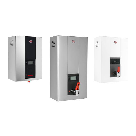
701, 702 & 703 Series
Boiling Water Units
702
Service. All printed copies not bearing this statement in RED are deemed "uncontrolled"
Published: 02/2017
70103 70303 70207
70105 70305 70210
70307 70215
TM063
Revision D
703
70225
70240
1
Advertisement
Table of Contents

Related Manuals for Rheem 70103


Summary of Contents for Rheem 70103
- Page 1 SERVICE INSTRUCTIONS 701, 702 & 703 Series Boiling Water Units TM063 Revision D Published: 02/2017 70103 70303 70207 70105 70305 70210 70307 70215 70225 70240 TM063 701, 702 & 703 Series Boiling Water Unit Service Instructions Revision D: Feb 2017 Service.
-
Page 2: Table Of Contents
Contents Introduction ..............................3 Safety Warning ............................3 BWU Model Identification ........................... 4 Preventative Maintenance .......................... 5 Specifications ............................. 6 Wiring Diagrams ............................7 Wiring Diagram 3 – 15L Models ......................... 7 Wiring Diagram 25 & 40L Models ......................7 Plumbing Diagram ............................ -
Page 3: Introduction
Introduction The information provided in these instructions is based on the Boiling Water Unit (BWU) being installed in accordance with the Installation Instructions provided with each appliance. Should you require further technical advice on a BWU, contact your distributor where genuine replacement parts are also available. -
Page 4: Bwu Model Identification
Finish W – White S – Stainless steel NZ or Australia Version NZ – New Zealand Version (Plug Type I, 15mm BSPP, Rheem branded) AU – Australia Version (Plug Type I, 12mm BSPP, Rheem branded) International Version Plug Qty 0 – No Plug 1 –... -
Page 5: Preventative Maintenance
Preventative Maintenance It is suggested for peak performance that the BWU be serviced every six months. Servicing must be performed by suitably qualified persons. Hot surface or liquid. Personal Protective Equipment (PPE) shall be worn to reduce the risk of burns or scalding. 1. -
Page 6: Specifications
Specifications 70103 ….. 70105 ….. 70207 ….. 70210 ….. 70215 ….. 70225 ….. 70240 ….. Lazer Boiling Water Unit 70303 ….. 70305 ….. 70307 ….. Storage capacity 3 Litres 5 Litres 7.5 Litres 10 Litres 15 Litres 25 Litres 40 Litres... -
Page 7: Wiring Diagrams
Wiring Diagrams Wiring Diagram 3 – 15L Models (Standard) (NZ model Pre 2014) Wiring Diagram 25 & 40L Models (Commercial 702 Series only) TM063 701, 702 & 703 Series Boiling Water Unit Service Instructions Revision D: Feb 2017 Service. All printed copies not bearing this statement in RED are deemed “uncontrolled” This document is stored and maintained electronically by... -
Page 8: Plumbing Diagram
Plumbing Diagram Water Inlet and Vent Connections Cold mains pressure water must be piped and connected to the RP½/15 inlet fitting located on the left hand side underneath the BWU. An accessible isolating valve must be installed near the BWU. The BWU contains an inlet strainer on the water inlet connection. - Page 9 4. After first time calibration or after drawing boiling water; the control board will incrementally fill and heat the water in the boiling water tank (4). After the first incremental fill, the water in the boiling water tank (4) is heated to Treq 2ºC at which time the control board will energise the inlet solenoid valve (3) until the water in the boiling water tank (4) is at...
- Page 10 BWU Sequence of Operation Component Diagram 3 – 15L Models 703 Display (Standard) Display (NZ Pre 2014) LH side Front view NZ 703 series RH side Control board relay Timer Low level probe Boiling water thermistor 10 High level probe Inlet solenoid valve Control board triac Boiling water tank...
-
Page 11: Operational Flow Chart - 701 & 702 Series
Operational Flow Charts Operational Flow Chart – 701 & 702 Series Plug In Control board Fault rectified Isolate Power Error Code Displayed Power On relay off Control board triac (2, 6) (element) disabled Control board Critical fault Inlet solenoid off relay on detected? (if on) -
Page 12: Operational Flow Chart - 703 Series
Operational Flow Chart – 703 Series Plug In Control board Fault rectified Isolate Power Power On relay off Control board triac (2, 6) (element) disabled Control board Critical fault Inlet solenoid off relay on detected? (if on) Inlet solenoid on Auto calibration Low level probe Low level probe... -
Page 13: Electronic Controller
Electronic Controller The control board or electronic controller is used to control the BWU by monitoring the water temperatures in the boiling water tank (via the boiling water thermistor) and processing commands received from the timer. The control board has a relay which when energised will switch power to the boiling water triac (boiling water element circuit). -
Page 14: Timer Functions
The timer also has a key lock function which when activated prevents access to the program functions. Timer Functions Function Mode Description Clock Set clock time. BWU ‘ON’ 24 hours 7 days. STD/AUTO BWU operates according to programmed AUTO ‘Set ON/OFF Times’. Set ON/OFF Times Program ON/OFF times for AUTO mode. -
Page 15: Setting The Clock
Setting the Clock 1. Press and release the (P) button, ‘Clock’ is displayed flashing on the screen. ) button to confirm selection. ‘Set Clock Day’ will be 2. Press and release the ( ✓ displayed on the screen with the day selection shown flashing. 3. - Page 16 5. Press and release the (▲) button until the desired minutes appear flashing on the screen. 6. Press and release the ( ✓ ) button to confirm selection. ‘SUN X:XX – X:XX Set OFF hour’ will be displayed on the screen. 7.
-
Page 17: Accessing Service Menu
) button to confirm selection. ‘Remaining Life XXXX Litres’ 2. Press and release the ( ✓ will be displayed on the screen where XXXX is the value of remaining filter life in litres. 3. Press and release the (X) or ( ✓... - Page 18 Activating Calibration Reset Mode Different altitudes will cause water to boil at different temperatures. To prevent the water in the boiling water tank from boiling continuously (which is energy inefficient) the BWU is fitted with an altitude calibration function which automatically operates when the unit is operated for the first time or if ‘calibration reset mode’...
- Page 19 Accessing Software Version 1. Press and release the (P) button until ‘Service’ is displayed on the screen. 2. Press and release the ( ✓ ) button to confirm selection. Existing error codes will be displayed on the screen. 3. Press and release the (▲) button until ‘Software Version’ is displayed on the screen.
-
Page 20: Eco Timer 703 Series
Activating Key Lock Function This function is for extra security to prevent tampering with the unit settings. Default setting is disabled. To activate keypad lock 1. Press and release the (P) button until ‘Keylock’ is displayed on the screen. 2. Press and release the (✓) button to confirm selection. ‘Key lock enable’ will be displayed on the screen. -
Page 21: Eco Timer Led Indication (Nz Pre-2014 Models)
Eco timer LED Indication (NZ Pre-2014 Models) The Eco timer has integral LED’s which indicate system status as follows: LED Status Description ‘Heating’ text On red flashing Calibration cycle in progress ‘Heating’ text Heating in progress (T0 ≤ Tb - 7ºC) On red solid ‘Ready’... -
Page 22: Eco Timer Led Indication (Standard)
Eco timer LED Indication (Standard) The eco timer has integral LED’s which indicate system status as follows: LED Status Description ‘HEATING’ text On red flashing Calibration cycle in progress ‘HEATING’ text On red solid Heating in progress ‘READY’ text On green solid Boiling water ready On green solid Sleep delay mode activated... -
Page 23: Components And Their Function
Components and their Function Timer: An electronic device which allows the user to program the BWU operating times and/or sleep mode function. Refer to page 14 for more information on timer operation. 701 & 702 Series have a 24 hr / 7day programmable timer. 703 series have an Eco function, refer to page 20 for Eco Sleep timer operation. -
Page 24: Common Complaints
Common Complaints When a complaint is lodged about the performance of a hot water system there are a number of causes that should be checked and eliminated. In an attempt to pinpoint the most likely cause it is important to discuss with the customer their reasons for the complaint, the duration of the problem, any change in circumstances or usage. -
Page 25: Error Codes (701 & 702 Series Only)
Error Codes (701 & 702 Series Only) The Timer has a ‘Service Menu’ which can display alphanumeric error codes (refer to Error Code Table below for error codes and their descriptions). To access ‘Error Codes’ operate the Timer in the following manner: 1. -
Page 26: Testing The Boiling Water Thermistor
Testing the Boiling Water Thermistor Unplug the boiling water thermistor at the thermistor wiring loom connector or control board plug socket and using a multimeter on the kilo-ohms scale, measure between the pins of the thermistor plug. As the resistance of the thermistor will change according to its temperature, the resistance measurements for the thermistor will need to be checked against the ‘Thermistor Temperature/ Resistance Table’... - Page 27 Fault Finding Charts, Fault Diagnosis Sequence (General Fault Finding Chart) Note:- 703 Series, if a proxy timer is not fitted, no error codes can be displayed. Fault General Fault Finding Chart Note: The following abbreviations are used throughout all fault finding charts in this service manual BWU = Boiling water unit BW = Boiling water Is an error code...
-
Page 28: Error Codes A, B, C, D
Error Code A BW thermistor Error Code A O/C or S/C Is BW thermistor ok? Replace BW thermistor. Refer to section on ‘Testing the Boiling Water Thermistor’. Ensure connector plug & socket Is BW thermistor is firmly connected. Replace wiring connector ok? connector if necessary. -
Page 29: Error Codes E, G
Error Code E To reset or deactivate filter Error Code E Expired filter counter refer to section on ‘Timer’ This error code will not affect appliance operation. Continue with fault diagnosis. Error Code G Calibration Error Code G time out Successful recalibration BWU will attempt Is error code G still... -
Page 30: Error Codes H, J
Error Code H & Error Code J Low level High level Error Code H Error Code J probe fault probe fault Restore water supply to BWU. Ensure stop cock or isolation Is water supply to valve is open. If an additional BWU ok? water filter is installed check to ensure it is not blocked. -
Page 31: Error Codes K, L N
Error Code K Chiller Compressor Error Code K fault 701, 702 & 703 Series BWU’s do not use compressor, error code K is not applicable. Continue fault finding. Error Code L Error Code N Excessive Error Code N temperature rise Ensure probes are not touching Is level probe ok? each other, the tank or the... -
Page 32: Fault Finding Chart 1
Fault Finding Chart 1 (Proxy timer recommended for fault finding on 703 series) Is 240 volts present Is the fuse blown at at the power point? Replace Fuse the switchboard? (TEST 1) Did the fuse blow again? Is 240 volts present Faulty fuse replaced. -
Page 33: Fault Finding Chart 1.1, 1.1A
Fault Finding Chart 1.1 Electrical Insulation Test Disconnect BW element wire from control board and Is reading below Replace BW element. megger between disconnected 1 mega-ohm? wIre and earth. Disconnect inlet solenoid wiring and megger between Is reading below Replace inlet solenoid. each inlet solenoid terminal 1 mega-ohm? and earth. -
Page 34: Fault Finding Chart 2, 3
Fault Finding Chart 2 (TEST 5A & 5B) (TEST 5A & 5B) (TEST 5A & 5B) Fault Finding Chart 3 i.e. additional people using BWU Is BWU of sufficient Has the usage Recommend a BWU of sufficient size for customers pattern changed capacity to meet customers needs? -
Page 35: Fault Finding Chart 4, 4.1 & 4.2
Fault Finding Chart 4, 4.1 & 4.2 (Proxy Display required 703 series or use Chart 4a) Is 240 volts present Is the fuse blown at at the power point? Replace fuse the switchboard? (TEST 1) Did the fuse blow again? Household wiring or power Is 240 volts present Faulty fuse replaced. -
Page 36: Fault Finding Chart 4A, Incl. (4.1 & 4.2)
Fault Finding Chart 4a, incl. (4.1 & 4.2) 703 Series – No Proxy Display Timer Is 240 volts present Is the fuse blown at at the power point? Replace fuse the switchboard? (TEST 1) Did the fuse blow again? Household wiring or power Is 240 volts present Faulty fuse replaced. -
Page 37: Fault Finding Chart 5
Fault Finding Chart 5 (Proxy Display required for 703 series or use chart 5a) Is 240 volts present Is the fuse blown at at the power point? Replace fuse the switchboard? (TEST 1) Did the fuse blow again? Is 240 volts present Faulty fuse replaced. -
Page 38: Fault Finding Chart 5A
Fault Finding Chart 5a 703 series Is 240 volts present Is the fuse blown at at the power point? Replace fuse the switchboard? (TEST 1) Did the fuse blow again? Is 240 volts present Faulty fuse replaced. Check at the power point? appliance operation. -
Page 39: Fault Finding Chart 6
Fault Finding Chart 6 Is leak from Repair or replace BWU tap. BWU tap? Remake hose connection/ Is leak from a hose or plumbing fitting or replace hose/ plumbing fitting? plumbing fitting. Is leak from inlet Tighten solenoid lock nut(s) or solenoid? replace solenoid. -
Page 40: Fault Finding Chart 7
Fault Finding Chart 7 Is noise only Is there mineral evident when electric build up on BW Replace Heating unit. heating cycle is on? heating unit? Poor quality water supply i.e. dam water. Flush tanks. Expansion & contraction noise Is noise a creaking associated with heating. -
Page 41: Fault Finding Tests
Fault Finding Tests Fault Finding Tests 1 – 3A Test 2A (3 – 15L models) Test 1 Ensure power point is switched on and using a Using a multimeter on the AC voltage scale, multimeter on the AC voltage scale, measure measure between the Active terminal (brown between the 3 pin sockets on the power point. - Page 42 Fault Finding Tests 3B – 6A Test 3B (25 & 40L models) Test 4 Using a multimeter on the AC voltage scale, Disconnect the boiling water probe at measure between the Active and Neutral control board and remove probe from terminals on the control board.
- Page 43 Fault Finding Tests 6A – 8 Test 6A (3 – 15L models) Test 6B (25 & 40L models) Disconnect the two wires from the boiling water Disconnect the two wires from the boiling element and using a multimeter on the ohms water element and using a multimeter on the scale, measure between the two element ohms scale, measure between the two...
- Page 44 Fault Finding Tests 9 Test 9 Using a multimeter on the ohms scale, measure between the orange and yellow wires. When the button is pressed the following result should be obtained: 10 – 13 ohms. (Note:- Eco timer ribbon wiring must be connected to do this test) TM063 701, 702 &...
-
Page 45: Electrical Safety Testing
Electrical Safety Testing There are some basic test procedures that should be carried out when the operation and function of a BWU electrical system is in doubt. Wear Personal Protective Equipment (PPE) when conducting step 1 of these procedures to reduce the risk of electric shock. Refer to the safety warning on electrical testing on page 3. -
Page 46: Component Replacement Procedures
Component Replacement Procedures When performing a component replacement procedure; ensure any escaping water is caught in a container and does flow onto any electrical components. When draining water from tank using the tap, some water will remain in the tank. ... - Page 47 Tap (Procedure 2B) 701 Tap, timer fascia replacement Isolate power and water supplies to BWU. Operate tap lever until water ceases to flow from tap. Follow procedure 1 to remove jacket surround Lift the tap lever, remove 2 retaining screws then the complete timer fascia and timer from the unit.
- Page 48 Water Outlet Pipe, Timer fascia (Procedure 4A) 702 & 703 Series 1. Isolate power and water supplies to BWU. 2. Operate tap lever until water ceases to flow from tap. 3. Remove jacket surround (refer to procedure 1). 4. Remove tap by following steps 3 – 4 of procedure 2A. 5.
- Page 49 6. Pull silicone tube away from inlet solenoid valve ensuring any escaping water does not flow onto electrical components. Note: Silicone tube is easier to remove if seal has been cracked first by levering with a small flat bladed screwdriver. 7.
- Page 50 Cord Set (Procedure 9) 1. Follow steps 1 – 13 of procedure 17 for removal of tank & insulation 2. Once the tank is removed the cord set is exposed. With a small flat bladed screwdriver the cord retaining tabs can be eased away from the cord to release it from the back plate.
- Page 51 Boiling Water Thermistor (Procedure 12) 6. Isolate power supply to BWU. 7. Remove jacket surround (refer to procedure 1). 8. Disconnect boiling water thermistor at wiring connector. 9. Withdraw boiling water thermistor from element dry well. 10. Complete reassembly in reverse order of above. If required, apply a small amount of heat transfer paste to the boiling water thermistor before reinserting into dry well.
- Page 52 Water Outlet Flange (Procedure 16A) 702 & 703 Series 1. Isolate power and water supplies to BWU. 2. Operate tap lever until water ceases to flow from tap. 3. Remove jacket surround (refer to procedure 1). 4. Remove tap by following steps 3 – 4 of procedure 2A. 5.
- Page 53 5. 702 & 703 series only: Remove water outlet pipe and timer fascia by following steps 5 – 6 of procedure 4A. 6. 701 Series: Disconnect silicone tubing from outlet tap and remove from tank insulation. 7. Remove element by following steps 5 – 6 of procedure 10. 8.
- Page 54 12. Remove inlet strainer by following steps 2 – 3 of procedure 5. 13. Remove inlet fitting lock nut by unscrewing locknut in an anticlockwise direction. 14. Pull silicone tube away from inlet solenoid valve and remove inlet solenoid valve complete with inlet fitting from BWU.
-
Page 55: Exploded View 1: 701 Series Office Model 3 & 5 Litre
Exploded view 1: 701 series Office model 3 & 5 litre Item Description Part Nº Item Description Part Nº Controller & Heatsink 317159 Jacket fixing screws x 4 315994 Cord set 315880 Electronic Timer 316963 Element 1.8kW 3L 317164 Tube Spout Teflon 319028 Tube 13mm Silicone Kit Element 2.4kW 5L... -
Page 56: Exploded View 2: 702 Series Commercial Model 7.5 - 40 Litre
Exploded view 2: 702 series Commercial model 7.5 - 40 litre Item Description Part Nº Item Description Part Nº Controller & Heatsink 7.5L - 317159 Tube 8mm Silicone Kit (1.4m) 316264 Controller & Heatsink 25L & Tube 13mm Silicone Kit 317190 319027 vent (1.0m) -
Page 57: Exploded View 3: 703 Series Eco Model 3 - 7.5 Litre
Exploded view 3: 703 series, Eco model 3 – 7.5 litre Item Description Part Nº Item Description Part Nº Controller & Heatsink 318263 Tube 8mm Silicone Kit (1.4m) 316264 Tube 13mm Silicone Kit Cord set 315880 319027 vent (1.0m) Element 3L 1.8kW 317164 Jacket fixing screws x 4 315994... -
Page 58: Document Revision History
02/17 add E.C.O. for 25/40L models Manufactured in New Zealand www.rheem.co.nz TM063 701, 702 & 703 Series Boiling Water Unit Service Instructions Revision D: Feb 2017 Service. All printed copies not bearing this statement in RED are deemed “uncontrolled”...
Need help?
Do you have a question about the 70103 and is the answer not in the manual?
Questions and answers