Table of Contents
Advertisement
Quick Links
Advertisement
Table of Contents

Related Manuals for WARRIOR W0703F


Summary of Contents for WARRIOR W0703F
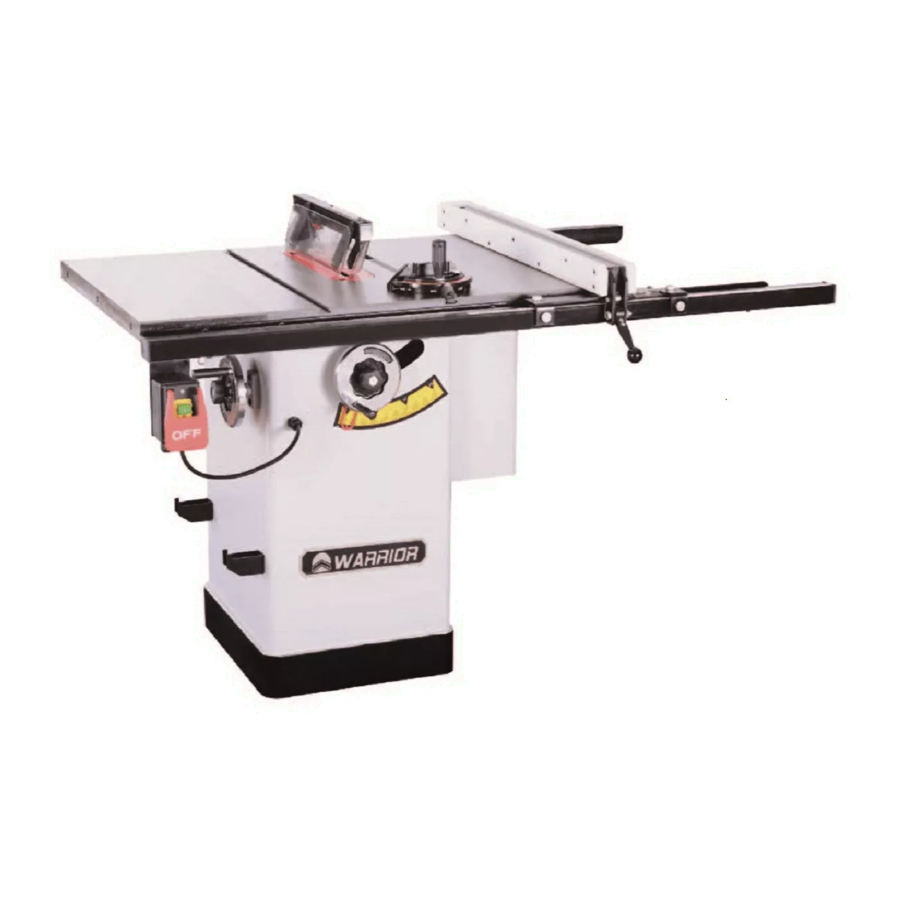
- Page 1 10" CABINET TABLE SAW INSTRUCTION MANUAL...
-
Page 2: Table Of Contents
Table of Contents INTRODUCTION ..........................1 Main Specifications........................1 SECTION 1: SAFETY ........................3 Yourself From Kickback....................6 SECTION 2: SETUP ........................7 SECTION 3: MAINTENANCE ......................16 SECTION 4: SERVICE ........................18 Adjusting 90° and 45°Positive Stops Aligning the Miter Slots to the Blade... -
Page 3: Introduction
INTRODUCTION Maximum Blade Diameter.......................... 10 in. Riving Knife/Spreader Thickness....................0.09 in. (2.3mm) Required Blade Body Thickness................0.074-0.082 in. (1.9-2.1mm) Required Blade Kerf Thickness................0.114-0.122 in. (2.9-3.1mm) Maximum Width Of Dado.......................... 3/4 in. Blade Tilt............................Left 0-45 deg. Arbor Size..............................5/8 in. Arbor Speed............................4200 RPM Arbor Bearings................... - Page 4 Paint............................Powder Coated Number Of Dust Ports............................1 Dust Port Size............................2-1/2 in. Riving Knife T-squre Fence System Extension Rails Available to Rip 36" Wide Includes Regular as well as Dado Blade Inserts Precision Ground Cast Iron Table with Beveled Edge All Machined Cast Iron Internal Structure Precision Ground Cast Iron Wings Clear Plastic Guard with Steel Splitter...
-
Page 5: Section 1: Safety
SECTION 1: SAFETY For Your Own Safety, Read Instruction Manual Before Operating this Machine The purpose of safety symbols is to attract your attention to possible hazardous conditions. This manual uses a series of symbols and signal words intended to convey the level of impor- tance of the safety messages. - Page 6 DISCONNECTING POWER SUPPLY. FORCING MACHINERY. GUARDS & COVERS. APPROVED OPERATION. NEVER STAND ON MACHINE. STABLE MACHINE. DANGEROUS ENVIRONMENTS. AWKWARD POSITIONS. ONLY USE AS INTENDED. USE RECOMMENDED ACCESSORIES. UNATTENDED OPERATION. CHILDREN & BYSTANDERS. MAINTAIN WITH CARE. REMOVE ADJUSTING TOOLS. CHECK DAMAGED PARTS. SECURING WORKPIECE.
-
Page 7: Additional Safety For Table Saws
Additional Safety for Table Saws HAND POSITIONING. FENCE. PUSH STICKS/BLOCKS. BLADE GUARD. CUT-OFF PIECES. BLADE ADJUSTMENTS. RIVING KNIFE. CHANGING BLADES. DAMAGED SAW BLADES. KICKBACK. DADO AND RABBET OPERATIONS. FEEDING WORKPIECE. CUTTING CORRECT MATERIAL. -
Page 8: Yourself From Kickback
Preventing Kickback Take the precautions below to avoid the most common causes of kickback: Statistics show that most common acci- dents among table saw users can be linked to kickback. Kickback is typically defined as the high-speed expulsion of stock from the table saw toward its opera- tor. -
Page 9: Section 2: Setup
SECTION 2: SETUP Needed for Setup This machine presents serious injury hazards to untrained users. Read through this entire manu- al to become familiar with Description the controls and opera- tions before starting the machine! Wear safety glasses dur- ing the entire setup pro- cess! This machine and its com- ponents are very heavy. - Page 10 Inventory shipped with this table saw. Lay the components to inventory them. Note: If you can't find an item, check the mounting location on the machine or examine the packag- ing materials carefully. Occasionally we pre-install certain components for shipping. Box Contents( Figures 1-2): Spreader/Blade Guard Assembly....1 Inventory contents...
- Page 11 Hardware Recognition Chart...
-
Page 12: Site Considerations
Site Considerations Weight Load Machine Data Sheet Children or untrained people may be seriously injured by this machine. Only install in an access restricted location. Electrical Installation Space Allocation Lighting See below for required space allocation. 39" 55" Figure 3. - Page 13 Assembly Place tilt-adjusting and elevation handwheels on the shafts. Engage the slot in the handwh- eels with the roll pin on the shaft as shown in Figure 4. Lock the handwheels with T-lock handles and a 8mm flat washer as shown in Figure 5.
- Page 14 Install the rear rail with four M8×35 cap screws, 8mm flat washers, 8mm lock washers and M8 Figure 10. hex nuts, as shown in Figure 7. Figure 8 Note: After reinstalling wings, remove all Figure 10. excess masking tape with a razor blade. five M6×12 cap screws, as shown in Figure 11.
- Page 15 9. Attach the motor cover by using M5×10 button head screw showed in Figure 13. Figure 15. Attach two tool rest brackets 12. Loose the screw on spliter bracket showed in Figure 13. Attach the motor cover Figure 16. 10. Attach the tool rest bracket to the motor cover by using Figure 14.
- Page 16 14. Attach the spliter on the bracket and tighten the 17. Attach the fence assembly to the rail as shown in screw and put the table insert back in place sh- Figure 21. Figure 18. owed in Figure 21. Fence Assembly 18.
-
Page 17: Test Run
Test Run Final Setup To complete the remaining assembly steps: Troubleshooting set parallel with miter slot. To test run the machine: the miter slot at the factory, which affects wh- ether the fence is parallel when mounted to t- he table. Install the blade guard. -
Page 18: Section 3: Maintenance
SECTION 3: MAINTENANCE Cleaning Always disconnect power to the machine before Cleaning this table saw is relatively easy. Vacuum performing maintenance. excess wood chips and sawdust, and wipe off the Failure to do this may remaining dust with a dry cloth. If any resin has b- result in serious person- uilt up, use a resin-dissolving cleaner to remove it. - Page 19 Bevel Gears adn Leadscrews The following are the main components that need to be lubricated: he gears are shown below Figure 25 hand- wheel is rotated, the gears turn the elevation lea- dscrew to raise/lower the motor housing assembly, In consideration of these mechanics, it is best to start the lubrication process with the blade com- Trunnion Slides pletely lowered.
-
Page 20: Section 4: Service
SECTION 4: SERVICE Troubleshooting Replace belt. - Page 21 Page Page 20 Page 20 Page Page Adjust fence parallel with blade. Replace blade. Adjust fence parallel with blade.
-
Page 22: Adjusting 90°And 45°Positive Stops
Adjusting 90°and 45°positive stops Your saw is equipped with positive stops that will 5. Loosen the screws, adjust the indicator to point to quickly and accurately position the saw blade at the 0°mark on the scale, and tighten the screws as 90°and 45°to the table. -
Page 23: Aligning The Miter Slots To The Blade
Aligning the miter slots to the blade The saw table was aligned at the factory so that 3. To adjust, loosen the four button cap screws on the trunnion access panel showed in Figure 33. the miter gauge slots are parallel to the saw bl- ade. -
Page 24: Spreader Or Riving Knife Alignment
Spreader or Riving Knife Alignment Checking Alignment Tools Needed Figure 36. To check the spreader/riving knife alignment: Adjusting Alignment Page 20 Figure 35 Adjusting Bent Spreader/Riving Knife Page 22 Figure 36 Adjusting Alignment Possible Tools Needed To adjust the spreader/riving knife position: Figure 35. -
Page 25: Fence Adjustments
Figure 37 Fence Adjustments Tools Needed Figure 37. Checking Alignment Steps 1–3 Height and Square To check/adjust the fence height and square- ness to the table: Figure 38. Adjusting Bent Spreader/Riving Knife Steps 1–4 Checking Alignment Page 22... - Page 26 Figure 40. Figure 38 Figure 38. Miter Gauge Adjustments Figure 38 Figure Figure 39 Figure 41. Tools Needed Figure 39. Checking/Setting 90° Stops Figure 40...
- Page 27 Figure 42. Figure 43. Figure 42. Step 4 Checking/Setting 45° Stops Figure 43.
Need help?
Do you have a question about the W0703F and is the answer not in the manual?
Questions and answers