Advertisement
Quick Links
Package Contents
Lock Side
Interface Cable
System Side
Interface Cable
Recommended Tools
Approved RFID Credential
Phillips P2 driver
Specifications
Voltage: 12–24 VDC ±10% (Power Supply not provided)
KS200-640 (Reader) Current Consumption:
12 VDC:
37 mA peak for Red and Green LED only
470 mA peak for Red and Green LED and Motor Drive
24 VDC:
18 mA peak for Red and Green LED only
245 mA peak for Red and Green LED and Motor Drive
3085006.002 Rev. B
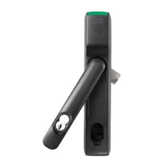
KS200-640
Server Cabinet Lock Series
Installation Instructions
Lock
Lock
DPS Cable
Optional Additional Tools:
Gang box to mount hub
SFIC Core for key override
Normally Open DPS Switches
Mounting
Handle
Plate
HES, Inc.
Phoenix, AZ
1.800.626.7590
www.hesinnovations.com
Mounting Screws
Cams (x3)
SFIC
Handling
Cam
Selector
1
Advertisement

Related Manuals for HES KS200-640


Summary of Contents for HES KS200-640
- Page 1 SFIC Core for key override Normally Open DPS Switches Specifications Voltage: 12–24 VDC ±10% (Power Supply not provided) KS200-640 (Reader) Current Consumption: 12 VDC: 37 mA peak for Red and Green LED only 470 mA peak for Red and Green LED and Motor Drive...
- Page 2 Operating Temperature: -10C to 50C Holding Force: 250 lbs External Interface Signals Summary: Lock Signal Lock Signal Direction and Wire Electrical Interface Logic Name Color P1-1/J1-1 Input, Power to Reader Red/24 AWG P1-12/J1-2 Dry Contact Tamper / Door Output, (0–35 VDC, Position + Yellow/24 AWG <100mA)
-
Page 3: System Overview
System Overview The KS200 is an radio-frequency (RFID) lock for server cabinet installation applications. The lock is capable of reading RFID credentials and providing that data to an electronic access control (EAC) system via Wiegand data signaling. The EAC determines whether user access should be granted or denied. When the EAC provides an active-high unlock signal to the lock in the access granted case, the KS200- 640 drives a motor to complete the unlock/lock cycle. - Page 4 1. Installing an SFIC Core NOTE 1: A key override (SFIC) provides a backup entry method in the rare case the KS200 or EAC is inactive (Recommended). NOTE 2: The included SFIC cam has been tested with Medeco and Sargent 6- or 7-pin SFIC cores. 1.
- Page 5 3. Installing the Lock 3. SLIDE lock into cutout. NOTE: (Optional) The DPS signal is closed when the handle is resting in its locked position. The DPS circuit can be extended to include normally open DPS switches arranged in a series to monitor additional doors and panels.
- Page 6 5. ATTACH rear bracket with screws. 6. ENSURE that the lock is fully secured and flush to the mounting Tamper Switch surface in order to depress tamper switch on back of device for correct operation. NOTE: If the tamper switch is not fully depressed, the lock opens the Tamper/DPS+/- contact.
- Page 7 5. Attaching the Wiring 1. CONNECT the 10-position Molex Micro-Fit 3.0™ Cable between the KS200 and the EAC. NOTE: It is recommended that 10-conductor, 24 AWG, cable be used. 2. ENSURE the following power cabling guidelines are followed: Wire AWG Supply Voltage Allowed Cable Length (ft.)* 20 AWG...
- Page 8 (4) cet appareil doit accepter toute interference, y compris des interférences qui peuvent provoquer un fonctionnement indésirable du périphérique. Conformité aux normes CE HES déclare par la présente que ces lecteurs à proximité sont conformes aux exigences essentielles et aux autres stipulations pertinentes de la Directive 1999/5/CE (http://ec.europa.eu/enterprise/sectors/rtte/files/guide2009-04- 20_en.pdf).
Need help?
Do you have a question about the KS200-640 and is the answer not in the manual?
Questions and answers
hi there, im slighlty usure as to wether to used both LED cores ,typically i would only use the green LED core (yellow) to the Led input on a lnl 1320 board , if i also need to use the blue (Red LED) where would i be terminating on the LNL board please or do i only use the Green, thanks for the help on this .