Table of Contents
Advertisement
Advertisement
Table of Contents

Related Manuals for Quest Payment Systems UT430

Summary of Contents for Quest Payment Systems UT430
- Page 1 Unattended Payment Terminal Installation & User Guide 152-0004-14...
- Page 2 This document contains proprietary information that is protected by copyright. All rights are reserved. No part of this document may be disclosed to third parties, photocopied, reproduced, or translated into another language without the prior written permission of Quest Payment Systems. This document is subject to change without notice.
-
Page 3: Table Of Contents
Connecting a Printer (optional) ..................16 3G Enabling ........................16 3G Enabling (optional) ...................... 17 Contactless - SAM Card Installation (optional) ..............21 Commissioning UT430 ...................... 22 General Operation ......................23 Software Controls ......................23 General Cleaning ......................25 Stolen Devices ........................26 FCC Statement ........................ -
Page 4: Introduction
Please read and understand these guidelines to ensure correct installation and successful commissioning of your UT430 Payment Terminal. Note: The communication and power ports available on your UT430 will depend on the configuration chosen at the time of purchase. This guide illustrates a UT430 with all possible ports included. Parts Checklist Please check that your 'UT430 Standard Kit’... -
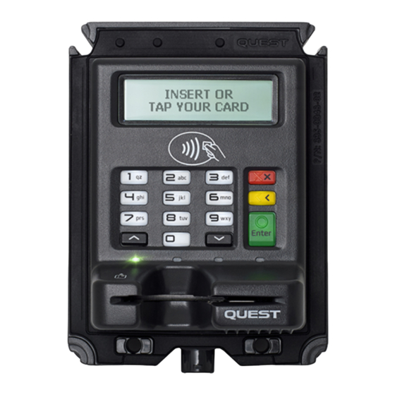
Page 5: Product Overview
2. Display 3. PIN Entry keypad 4. Removal detection switches 5. Tap Zone - Contactless cards 6. Contactless transaction status indicators 7. Power indicator 8. Backplane connections 9. Drain tube attachment 152-0004-14 UT430 Installation Guide Page 2 2 2 2... -
Page 6: Machine Requirements
Machine Requirements PANEL MOUNTING UT430 has been designed to fit the recommended hole size as prescribed by the European Vending Association, document: CASHLESS VENDING SPECIFICATION EVA CVS 1.3 1. Cut-out Size: 86.4 x 108.7, 4mm Max Corner Radius (3mm minimum) 2. - Page 7 INTERNAL CLEARANCE SPACE REQUIRED Please observe the space requirements inside the machine. IMPORTANT Note: If UT430 is connected via Ethernet, a clearance greater than 20mm may be required behind UT430 (dependant on cable style) 152-0004-14 UT430 Installation Guide Page 4 4 4 4...
- Page 8 Please observe the space requirements outside the machine. IMPORTANT Note: Ensure the sides of the metal enclosure near the protruding portion of the UT430 are kept the minimum distances away as shown below. This will ensure reliable operation of the Contactless reader.
- Page 9 MECHANICAL SECURITY If UT430 is mounted on a hinged door or fascia panel, ensure the door or panel cannot be removed during normal operation. This aspect is important to maintaining your PCI compliance. RECOMMENDATIONS FOR PIN ENTRY PRIVACY 1. It is imperative that UT430 is installed in the machine in such a manner that prevents visual observation of the PIN entry process.
-
Page 10: Installation Into A Machine
1. Ensure machine has been designed in accordance with the recommended cut out and mounting studs prior to beginning installation (see Appendix A) 2. From inside the machine, place UT430 through the cut out and over the internal mounting studs. (UT430 is designed to protrude through the hole in the machine) 3. - Page 11 5. Check operation of Card slot by inserting a card, if the card does not slide freely, loosen the thumbscrews until the card slot is free running. 6. Ensure there is no rattle and no visible gap between the flange of UT430 and the machine mounting surface.
- Page 12 DRAIN TUBE If UT430 is situated where moisture could enter the card slot, a Vinyl drain tube should be fitted to direct water safely out of the machine. The tube can be pushed onto the barb fitting on UT430. The other end of the tube must exit the machine in a safe manner. Length and exit location of tube to be determined by machine manufacturer.
-
Page 13: Power Requirements & Communications
Power Requirements & Communications NOTE The UT430 must be supplied by a Limited Power Source (LPS) or a Class 2 power supply in accordance with the U.S. National Electrical Code. POWER REQUIREMENTS Input Voltage Range 5V-34V DC, 14.4W max Power can be supplied to UT430 in 3 different ways dependant on your implementation. Choose one method below: 1. -
Page 14: Communications Setup
1. SERIAL CONNECTION Connect UT430 following the instructions on the diagram below: the Modular plug to the UT430 modular socket labelled POS the DB9 POS plug to the Machine controller the 12V Power Adaptor to a 240V Power outlet (GPO) - Page 15 2. USB CONNECTION (OPTIONAL) UT430 has a full size 'B type' socket. Connect the 'B type' end of your USB cable to the socket labelled USB. Connect the other end (type A) to the USB port on the machine controller.
- Page 16 USB port pinout on UT430 Signal Description Data - Data + Ground 152-0004-14 UT430 Installation Guide Page 13 13 13 13...
- Page 17 Connect UT430 by fitting: the MDB cable from the machine controller to the 6 pin socket labelled MDB MiniFit Jr Plug Housing, Dual Row (Molex) - 6 POS Plug Housing (Part No.39-01-2060) MDB port pinout on UT430 Signal Description MDB-VS...
- Page 18 4. ETHERNET CONNECTION (OPTIONAL) UT430 has a modular 8P8C connector (commonly referred to as RJ45) that follows the TIA/EIA-568 wiring standard. If an optional Ethernet Communication module has been fitted to UT430: Connect your LAN Cable to the UT430 socket labelled LAN The Ethernet port is for communications only.
-
Page 19: Connecting A Printer (Optional)
Connecting a Printer (optional) UT430 allows connection of one Slave RS-232 Serial Receipt printer. Connect the Modular plug from the printer to the socket on UT430 labelled PRN PRN port pinout on UT430 Signal Description Not Connected PRN-TX External Printer Transmit (Output) -
Page 20: Enabling (Optional)
3G Enabling (optional) UT430 is designed to accept a 3G Communications module (only available from Quest). The standard configuration of UT430 does not include this 3G module unless arranged prior. However, the module can be fitted in the field by a qualified technician (contact Quest to obtain detailed instructions). - Page 21 152-0004-14 UT430 Installation Guide Page 18 18 18 18...
- Page 22 3. Connect your external antenna (do not over tighten). Note: If fitted, remove the protective cap from the SMA on UT430 and screw the antenna cable onto the SMA 4. Orientate your SIM Card as shown below and push it into the slot marked SIM until you feel a click, now release your finger 5.
- Page 23 Or, fitting a 12V cable to the PWR port (See Power requirements section in this document) TO REMOVE THE SIM CARD 1. To remove the SIM card, push to eject it, then simply pull the card out. 152-0004-14 UT430 Installation Guide Page 20 20 20 20...
-
Page 24: Contactless - Sam Card Installation (Optional)
1. Orientate the SAM Card as shown below and push into slot until card stops. (Note: a fully installed SAM card will protrude 4mm) REMOVAL 1. To remove a SAM card, use your fingers to pinch the protruding portion of the card and withdraw it. 152-0004-14 UT430 Installation Guide Page 21 21 21 21... -
Page 25: Commissioning Ut430
Commissioning UT430 Commissioning a UT430 can only take place once the unit is fully installed into the machine as described earlier in this document. UT430 is preloaded by Quest with your nominated Bank’s keys, and an agreed Passcode file. Once the installer completes the first installation of UT430 into the machine and connects power, the device will be ready for normal operation. -
Page 26: General Operation
If the card is Magnetic stripe only, you will be prompted to remove the card (UT430 will read the magnetic stripe when withdrawing the card from the device) When prompted, tap your Contactless enabled card near the contactless symbol. - Page 27 UT430 The following section outlines commands that can be performed on the UT430 Keypad. 1. To accept a prompt: Press Enter 2. To decline a prompt: Press X (Cancel) 3. To enter menu: Hold X (Cancel) & Press 4 4. To move UP the menu list: Press ^ 5.
-
Page 28: General Cleaning
Card Reader Cleaning Cards are designed to clean the Magnetic stripe reader (MSR) and Smart card / EMV (chip and pin) card reader. UT430 uses a hybrid reader where both MSR and Chip & PIN readers are combined in the one card slot. -
Page 29: Stolen Devices
Stolen Devices If a UT430 is stolen, you must immediately notify the following parties: 1. Your Bank Ask your Bank to cancel the PINpad ID and Terminal ID associated with the stolen terminal 2. The Police File a report with your local police station so they aware and investigate the incident 3. - Page 30 Please refer to your maintenance agreement for specific information on available contact hours. When seeking support, please have your serial number ready. Quest Support Desk Support Phone: +61 3 8807 4444 Support Email: support@questps.com.au 152-0004-14 UT430 Installation Guide Page 27 27 27 27...
- Page 31 Hardware Returns If you’re experiencing an issue with the UT430 product, please call us. Our Support team may be able to resolve your issue over the phone. If not, we may advise you to return the hardware to us for review and repair.
-
Page 32: Fcc Statement
• Consult the dealer or an experienced radio/TV technician for help. Warning: Any changes or modifications not expressly approved by Quest Payment Systems could void the user's authority to operate this equipment. This device complies with part 15 of the FCC rules. Operation is subject to the following two conditions: (1) this device may not cause harmful interference, and (2) this device must accept any interference received, including interference that may cause undesired operation. -
Page 33: Warranty
HARDWARE WARRANTY (QUEST DOC# 510-0147-04) Quest Payment Systems Pty Ltd (Quest) hardware products are warranted against defects caused by faulty workmanship and materials for twelve (12) months from the date of supply for new products, and ninety (90) days from the date of repair for refurbished or repaired products. - Page 34 SOFTWARE WARRANTY (QUEST DOC# 510-0147-04) SOFTWARE LICENCE: Quest Payment Systems Pty Ltd (Quest) grants the licensee a non-exclusive licence to use the Software in this package on one (1) computer node, upon payment of an agreed fee. Quest retains title to and ownership of this copy and all backup copies and all intellectual property rights related to the Software.
-
Page 35: Appendices
Appendices APPENDIX A - PANEL MOUNT SPECIFICATION Quest Doc# “127-0294-04 - UT430 Panel Mount Specification” Available in PDF and DXF file formats 152-0004-14 UT430 Installation Guide Page 32 32 32 32... - Page 36 APPENDIX B - CONNECTOR PINOUTS ON UT430 Signal Description Not Connected 12V DC Supply Voltage Ground Ground Signal Description MDB-VS MDB Supply Voltage Ground WAKEUP MDB Bidirectional Wakeup MDB-TX MDB Transmit (Output) MDB-RX MDB Receive (Input) MDB-GND MDB Isolated Ground (for MDB-TX and -RX)
- Page 37 227 Burwood Road, Hawthorn, Victoria, Australia 3122 Office Phone: +61 3 8807 4400 Support Phone: +61 3 8807 4444 Support E-mail: support@questps.com.au...
Need help?
Do you have a question about the UT430 and is the answer not in the manual?
Questions and answers