Table of Contents
Advertisement
Quick Links
Advertisement
Table of Contents

Related Manuals for Epson ELPMB45


Summary of Contents for Epson ELPMB45
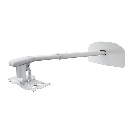
- Page 1 ELPMB45 Installation Guide...
-
Page 2: Safety Instructions
About This Installation Guide This guide describes how to mount the short-throw projectors BrightLink® 536Wi and PowerLite® 520/525W/ 530/535W to a wall using the Epson® wall mount. Not all models are available in all markets. Safety Instructions For your safety, read all the instructions in this guide before using the wall mount. Incorrect handling that ignores instructions in this guide could damage the wall mount or could result in personal injury or property damage. - Page 3 Use M8 nuts and bolts. Nuts and bolts smaller than M8 could cause the wall mount to fall. Epson accepts no responsibility for any damage or injury caused by lack of wall strength or inadequate installation.
- Page 4 Caution Do not install the wall mount in a location where the operating temperature for your projector model may be exceeded. Such an environment may damage the projector. Install the wall mount in a place free from excessive dust and humidity to prevent the lens or optical components from becoming dirty.
-
Page 5: Package Contents
1 Package Contents Arm unit Arm plate Adjustment Projector attachment plate Wall plate Wall plate cover Arm cover Hexagonal wrenches Cable cover Shape Name Quantity M4 × 12 mm hexagon socket head cap bolt with washer M4 × 12 mm hexagon socket head cap bolt without washer M4 ×... -
Page 6: Specifications
2 Specifications Item Specification Weight Approx. 24 lb (11 kg) Maximum load capacity 12.1 lb (5.5 kg) Arm length 59.4 inches (1510 mm) (from wall plate attachment point to arm cover point) Vertical angle adjustment range 0 to 5.3 inches (0 to 134 mm) (arm length minimum) 0 to 9.1 inches (0 to 230 mm) (arm length maximum) Vertical tilt adjustment range -7 to 17°... -
Page 7: Connecting Devices
USB cable (for computer video and audio Document camera output or interactive features) (Epson DC-06) Dedicated USB cable (supplied with document camera) For Interactive Use For the best performance, connect your computer to the projector using a VGA or HDMI cable. -
Page 8: Connecting Computers
If both the projector and computer are connected to the same network by an Ethernet cable, users can project through the network. You must install the EasyMP® Network Projection software on the computer. This software is available on the Epson Projector Software CD that came with the projector or at epson.com/ support (U.S.) or epson.ca/support (Canada). -
Page 9: Connecting Document Cameras
Document cameras have several different types of ports for connecting to the projector. For cameras that have USB ports, such as the Epson DC-11 and Epson DC-06, the best way to connect is directly to the computer’s USB port, as shown below. This will enable full interactivity and dual pen support (using Easy Interactive Tools software) on the document camera image. -
Page 10: Connecting Audio
• Video (composite video) S-video connection HDMI connection Component to VGA connections Composite video connection Connecting Audio A variety of audio connections are available: • You can connect a dynamic microphone to the Mic port and output the sound through the projector. •... -
Page 11: Positioning The Projector
4 Positioning the Projector BrightLink 536Wi and PowerLite 525W/535W can project up to 113 inches diagonally for a WXGA image or 100 inches diagonally for an XGA image using this mount. PowerLite 520/530 can project up to 106 inches diagonally for an XGA image. You can project onto a pre-installed whiteboard or directly onto a plain wall. The height of the included wall mount determines how high the image appears on the wall or whiteboard. - Page 20 If you have a pre-existing interactive whiteboard, refer to the table below to identify common models and sizes. If your board is listed here, use the dimensions to reference the installation requirements found on pages 13 through 20. Interactive whiteboard sizes Diagonal size 16:10 WXGA 4:3 XGA...
-
Page 21: Installing The Projector
M8 could cause the wall mount to fall. ❏ Epson accepts no responsibility for any damage or injury caused by lack of wall strength or inadequate installation. At the point where the wall mount is installed, make sure there is a gap of 16 to 26 inches (410 to 660 mm) from the top of the image projected onto the white board to the ceiling. - Page 22 Position the wall plate over the marks you made in step 1, and then mark the position of the wall plate’s mounting holes as shown in the following illustration. Use at least three mounting holes. If you are securing the wall plate in four places, drill the holes indicated by A or B in the illustration below.
-
Page 23: Assemble The Wall Mount
Assemble the wall mount Attach the adjustment unit to the arm unit. Partially tighten the M4 × 12 mm hexagon socket head cap bolt and M8 × 16 mm hexagon socket head cap bolt using the hexagonal wrenches (M4 and M8). You need to change the position of the adjustment unit screws (B) if you are using the wall mount with a product other than the PowerLite 520/525W/530/535W or BrightLink 536Wi projectors. -
Page 24: Route The Cables Through The Arm Unit
Problems may occur if you use this product without routing the cables through the arm unit. Route the USB cable so that the type B connector emerges on the projector side. Epson recommends labeling any duplicate cables so that additional connections can be more easily identified. -
Page 25: Attach The Attachment Plate To The Projector
Attach the attachment plate to the projector Place the projector upside down. Attach the attachment plate to the projector using the hexagonal wrench (M4) and five M4 × 12 mm bolts with washers/spring washers. M4 × 12 mm hexagon socket head cap bolt with washer/spring washer (×5) Attachment plate Projector lens side... -
Page 26: Adjust The Arm Length
Adjust the arm length Loosen the screw on the arm ( Adjust the length of the arm using the measure on the bottom to match the projection distance recommended in “Positioning the Projector” on page 12 ( After adjusting the length, secure the arm position temporarily by tightening the screw on top ( Connect the power cord and other cables to the projector Connect any necessary cables such as the power cord, computer cable, HDMI cable, audio cables, and... -
Page 27: Attach The Cable Cover To The Projector
An optional cable management system is available from Epson (part # ELPCK01). Attach the cable cover to the projector Take up the cable slack, and then attach the cable cover and use a cross-head screwdriver to tighten the screws (2) and secure the cable cover. -
Page 28: Attach The Arm Cover
Firmly tighten the screws on the arm unit and adjustment unit using the hexagonal wrenches (M4 and M8). Warning Tighten all screws firmly. Otherwise, the projector or wall mount may fall and cause personal injury or property damage. 11. Attach the arm cover Secure the arm cover with a hexagonal wrench (M4) and an M4 ×... -
Page 29: Attach The Wall Plate Cover
12. Attach the wall plate cover Secure the wall plate cover with a hexagonal wrench (M4) and three M4 × 12 mm hexagon socket head cap bolts. Wall plate cover M4 × 12 mm hexagon socket head cap bolt (×3) Wall plate cover Depending on how the cables are wired, you may need to cut out parts of the wall plate cover to allow the cables to be passed through it. -
Page 30: Using The Easy Interactive Function (Brightlink Models Only)
Appendix Using the Easy Interactive Function (BrightLink models only) After you install a BrightLink model, you need to perform calibration to align the positions of the cursor and interactive pens. In order to use the Easy Interactive Tools software, you must first install the software on the computer. OS X users also need to install a driver that enables the pens to work.