Table of Contents
Advertisement
Advertisement
Table of Contents

Subscribe to Our Youtube Channel
Related Manuals for Oben AT-3535


Summary of Contents for Oben AT-3535
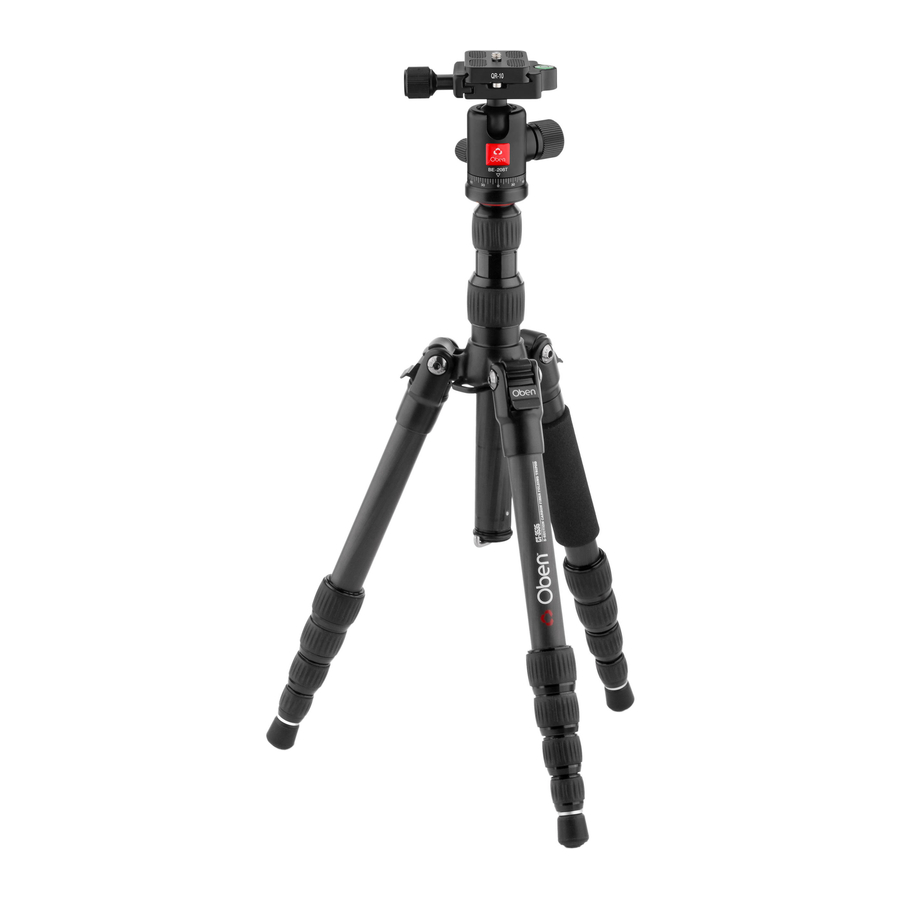
- Page 1 3500 Series Tripod Kit You’re on steady ground ™...
- Page 2 INTRODUCTION Thank You for choosing Oben! This versatile and durable Oben tripod and ballhead is a compact and lightweight kit that sets up quickly, folds up neatly into its own carry bag, and offers a variety of options ideal for the photographer on the go.
-
Page 3: Table Of Contents
TABLE OF CONTENTS Key Features Ballhead Operation The Tripod Mounting Screw Mounting the Ballhead Main Locking Knob Operation Mounting the Quick-Release Plate to the Camera Mounting the Camera and Quick-Release Plate to the Ballhead Tension Thumbscrew (BC-217T & BC-226T only) Adjusting the Friction (BC-217T &... -
Page 4: Key Features
KEY FEATURES... - Page 5 KEY FEATURES Baseplate with Dual 3/8″ and 1/4″-20 head mounting screw Two-piece center column (AT/CT-3535 and AT-3585) One-piece center column (AT-3565) Low-angle center column Center column locking collar Center column twist lock (AT/CT-3535 and AT-3585) Strap mount Leg angle adjustment lock Integrated monopod Retractable and removable weight hook 180°...
- Page 6 KEY FEATURES...
- Page 7 KEY FEATURES Quick-release plate Bubble level 1/4″-20 UNC mounting screw Quick-release knob Pan knob Locking index scale (BC-217T & BC-226T) Main locking knob Tension thumbscrew (BC-217T & BC-226T) Panoramic base with 360° markings 90° groove...
-
Page 8: Ballhead Operation
OPERATION OPERATION Ballhead Operation The AT/CT-Series tripod and BC/BE-Series ballhead come assembled. During normal operation, the ballhead will occasionally have to be removed in order to make adjustments to the tripod. THE TRIPOD MOUNTING SCREW The tripod includes a mounting screw with a 3/8″... -
Page 9: Mounting The Ballhead
OPERATION OPERATION MOUNTING THE BALLHEAD When returning the ballhead to the tripod, follow these steps: 1. Tighten all of the knobs on the head. 2. Align the ballhead socket with the tripod mounting screw. 3. Rotate the ballhead clockwise onto the tripod and tighten it by hand. - Page 10 Oben quick-release clamp. Please test all camera and lens plates made by manufacturers other than Oben to ensure compatibility. MOUNTING THE CAMERA AND QUICK- RELEASE PLATE TO THE BALLHEAD After mounting the quick-release plate to your camera, make sure...
-
Page 11: Mounting The Camera And Quick-Release Plate To The Ballhead
OPERATION Warning: Always use one hand to secure the camera while adjusting the ballhead, and make sure that the lock is engaged before letting go of the camera. MAIN LOCKING KNOB OPERATION The single locking knob locks and unlocks the ballhead, which allows for changing the position of the camera. -
Page 12: Tension Thumbscrew (Bc-217T & Bc-226T Only)
OPERATION Ballhead Operation (continued) TENSION THUMBSCREW (BC-217T & BC-226T BALLHEADS) The tension thumbscrew is integrated into the main locking knob. It’s used to control the amount of friction on the ball in order to maintain strict control when positioning it. ADJUSTING THE FRICTION (BC-217T &... - Page 13 OPERATION If you want to mount a heavier camera and lens combination, you will need to repeat this process of increasing the tension on the ball by following the same steps with the new camera/lens combination. Important: To lower your minimal friction limit, follow these steps: 1.
-
Page 14: Panoramic Base
OPERATION Ballhead Operation (continued) PANORAMIC BASE The base of the ballhead can be independently rotated 360°. The base is controlled by loosening the pan knob. (The smallest knob at the base of the head.) 1. Twist the knob counterclockwise to unlock the base. 2. -
Page 15: Leg Angle Adjustment
OPERATION LEG ANGLE ADJUSTMENT For stable support when shooting on uneven terrain, each leg can be adjusted to a preset angle of 22.5°–24°, 50°, or 80°. To set the leg angle, do the following: 1. Press and hold the leg angle adjustment lock. -
Page 16: Low-Angle Setup
OPERATION Tripod Operation (continued) AT/CT-3535, AT-3585 1. If more height is needed, turn the center column twist lock counterclockwise and extend the upper center column to the desired height. 2. Turn the twist lock clockwise to secure the column. Note: Make sure the column is secure, but do not overtighten to avoid damaging the tripod. - Page 17 OPERATION Using the Low-Angle Center Column 1. Remove the ballhead from the tripod. 2. Loosen the set screw and unscrew the baseplate from the center column. 3. Unscrew the weight hook from the bottom of the center column. 4. Loosen the locking collar and slide the center column off of the tripod.
- Page 18 OPERATION Tripod Operation (continued) Reversing the Center Column Reversing the center column allows for mounting the camera upside down in order to get close to the ground or surface. To reverse the center column, do the following: 1. Unscrew the weight hook from the bottom of the center column.
-
Page 19: Counterweight
OPERATION 3. Unscrew the weight hook from the bottom of the center column. 4. Loosen the locking collar and remove the center column from the tripod. 5. Attach the baseplate and the ballhead to the low-angle center column and slide it into the tripod from underneath so that the ballhead is facing down toward the ground. -
Page 20: Spiked Feet
Spikes are for soft ground, grass, sand, and uneven terrain. To expose the spikes, follow these steps: AT-3535 and CT-3535: Remove the rubber feet by pulling them off. Adjust the leg height according to your needs. AT-3565 and AT-3585: 1. -
Page 21: Folding Legs
OPERATION 3. Loosen the locking collar and slide the center column out of the tripod. 4. Screw the end of the center column that housed the weight hook onto the end of the monopod leg. Note: As an alternative to using the ballhead, the camera can be mounted directly to the baseplate. -
Page 22: Specifications
SPECIFICATIONS AT-3535 CT-3535 AT-3565 AT-3585 Maximum Height 51.6″ 51.6″ 61.7″ 66.5″ (1.3 m) (1.3 m) (1.56 m) (1.7 m) with Center Column Extended Maximum Height 41.4″ 41.4″ 53.6″ 59.7″ (1.0 m) (1.0 m) (1.4 m) (1.5 m) w/o Center Column... -
Page 23: Warnings
OPTIONAL ACCESSORIES Oben Tripod Strap with Quick-Release Loop and Spring Lock • TS-10 • TS-100 Oben Deluxe Tripod Strap with Swivel Clip •... - Page 24 www.obensupports.com...
Need help?
Do you have a question about the AT-3535 and is the answer not in the manual?
Questions and answers