Polycom MGC-50 Getting Started Manual
Polycom network hardware user manual
Hide thumbs
Also See for MGC-50:
- Hardware installation manual (170 pages) ,
- Getting started manual (164 pages) ,
- Release note (94 pages)
Table of Contents
Advertisement
Quick Links
Advertisement
Table of Contents

Related Manuals for Polycom MGC-50


Summary of Contents for Polycom MGC-50
- Page 1 MGC-50/MGC-100 Getting Started Guide Version 8.0...
- Page 2 Polycom, Inc. Information contained herein is subject to change without notice and does not represent a commitment of any type on the part of Polycom, Inc. Polycom and Accord are registered trademarks of Polycom, Inc.
-
Page 3: Regulatory Notices
If requested, the FCC registration Number and REN must be provided to the telephone company. Any repairs to this equipment must be carried out by Polycom Inc., or our designated agent. This stipulation is required by the FCC and applies during and after the warranty period. - Page 4 Following the provisions of the Council Directive 1999/EC on radio and telecommunication terminal equipment and the recognition of its conformity. Regulatory Notices Russian Communication Certificate The MGC-100 and MGC-50 comply with the Russian Ministry of Communication requirements stated in certificate OC/1-MM-15.
-
Page 5: Table Of Contents
MGC-100 Components Location ......2-2 MGC-50 Components Location ......2-6 MGC Unit Components . - Page 6 MGC-50/MGC-100 Getting Started Guide Video Conference Attributes ....... 4-3 Entry Queue ..........4-4 Basic Operations .
- Page 7 Defining a New Video Meeting Room ..... . . 7-12 Management Tools ....... . . 8-1 Resource Report .
- Page 8 MGC-50/MGC-100 Getting Started Guide...
-
Page 9: Before You Begin
Before You Begin This Getting Started Guide provides information on the installation and basic operation of your MGC-50/100. For more information on defining and running conferences, defining IVR services and managing the system, refer to the MGC Manager User’s Guide Volumes I & II and the MGC Administrator’s Guide included with the system. -
Page 10: Mgc Unit Main Features
Chapter 1 - Before You Begin MGC Unit Main Features The MGC unit offers the following features: Supports a large number of ports (48 for the MGC-50, 96 for the MGC- • 100) running at 128 Kbps Universal slots, telco grade high availability with hot-swappable •... -
Page 11: Mgc-50/Mgc-100 Specifications
MGC-50/MGC-100 Specifications Table 1-1 lists the specifications of the MGC-50 and the MGC-100 units. Table 1-1: MGC Unit Specifications Physical Height Width Depth Weight Free space above the MCU rack H.323 Protocols Audio Video Data H. 320 Protocols Audio Video... - Page 12 Reservation systems Environment Operating temperature Storage temperature Relative humidity Operating altitude H.221, BONDING, Multi-Rate (H0) MGC-50/MGC-100 ISDN: T1 PRI, E1 PRI, Multirate ISDN, NFAS, Leased lines-T1/E1, Switched 56 IP (H.323 and SIP): T1-CAS T1-CAS lines for Audio Only connections ATM: 25 (FVC.COM), 155 (FVC.COM)
- Page 13 Amp at 100 VAC, 5 Amp at 240 VAC protected by a 15 Amp circuit breaker. MGC-50/MGC-100 Getting Started Guide MGC-100 -48 VDC MGC-100 • AC Voltage - 15 Amp at 100 VAC and 7.5 Amp at 220 VAC protected by a 15 Amp circuit breaker.
-
Page 14: Network Equipment, Numbers And Addresses
• Directory number range(s) • Switch Type • Line Coding • Line Framing • Numbering Plan • Numbering Type • If the MGC-50/100 has to be connected to the public ISDN network, an external CSU or similar equipment is needed. -
Page 15: Hardware Description
Hardware Description The following components make up the MGC unit: Main Control Module • Backplane • Power Supply Module(s) • Fans • Alarms port • Functional Modules • — — — — — — — — Input/Output cards • ISDN/T1-CAS Net-2/4/8 IP/IP+ cards MUX+ Audio+12/24, Audio+24/48, Audio+48/96... -
Page 16: Mgc-100 Components Location
Chapter 2 - Hardware Description MGC-100 Components Location Figure 2-1 shows the front panel of the MGC-100. The front panel provides access to the Main Control Module, the Functional Modules, and the Power Supply Modules. Status LEDs on the Main Control Module, Functional Modules, and Power Supply Modules indicate the status of the system. - Page 17 The Alarms port provides dry contacts for critical, major, and minor alarms. Main Switch and Circuit Breaker AC Inlet Figure 2-2: MGC-100 Rear Panel with External Connectors MGC-50/MGC-100 Getting Started Guide Slot A RS232 Network Connectors Connectors...
- Page 18 Chapter 2 - Hardware Description Figure 2-3 shows the front panel of the MGC-100 NEBS Standard. The front panel, as in the MGC-100, provides access to the Main Control Module, the Functional Modules, and the Power Supply Modules. Status LEDs on the Main Control Module, Functional Modules, and Power Supply Modules indicate the status of the system.
- Page 19 MGC-50/MGC-100 Getting Started Guide Figure 2-4 shows the rear panel of the MGC-100 NEBS Standard. The rear panel, as in the standard MGC-100, provides access to the network I/O card connectors and fans. I/O cards are inserted via the rear panel.
-
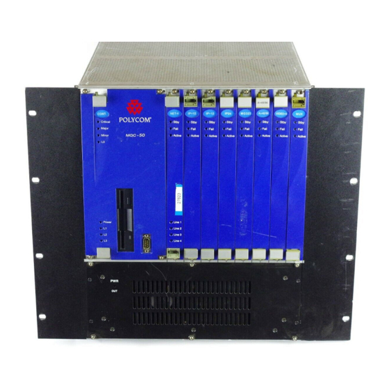
Page 20: Mgc-50 Components Location
Chapter 2 - Hardware Description MGC-50 Components Location Figure 2-5 shows the front panel of the MGC-50. The front panel provides access to the Main Control Module, the Functional Modules, and the Power Supply Module. Status LEDs on the Main Control Module, Functional Modules, and Power Supply Module indicate the status of the system. - Page 21 Figure 2-6 shows the rear panel of the MGC-50. I/O cards are inserted via the rear panel. The rear panel also provides access to the fans, power supply module, network connections, additional communications ports, the main power switch, AC inlet, and fuse.
-
Page 22: Mgc Unit Components
Chapter 2 - Hardware Description MGC Unit Components The following table describes the MGC components. A more detailed description is found in the MGC-50/MGC-100 Hardware & Installation Manual. Table 2-1: MGC Component Description Component Control Module Backplane Power Plane Power Supply... - Page 23 The Functional Modules, also known as cards, perform Modules the various audio, video, and data processing functions for the MGC unit. Both the MGC-100 and the MGC-50 use the same functional modules.Any module can be inserted into any slot and servicing can be performed while the system is in operation.
- Page 24 Chapter 2 - Hardware Description 2-10...
-
Page 25: Initial System Configuration
Initial System Configuration The MGC-50/MGC-100 requires basic configuration before you can start Initial IP running conferences. Configuration Initial IP Configuration Installing the MGC Manager The system is shipped with a default IP address: 129.254.4.8. Ordinarily, you need to change the MCU’s default IP address to the IP address appropriate for the site's LAN. - Page 26 MGC-50/MGC-100 Getting Started Guide Figure 3-2: MGC-50 Rear Panel Connect a monitor and the keyboard to the appropriate connectors in the MCU. Figure 3-3: Attaching the Monitor and Key Board to the MGC-100 COM 1 MUSIC LINE IN COM 1...
- Page 27 COM 1 Figure 3-4: Attaching the Monitor and Key Board to the MGC-50 Insert the DOS diskette into the MCU diskette drive. Reset the MCU (by turning it off and then on), or if it is turned off, turn it on.
-
Page 28: Installing The Mgc Manager
MGC Manager software on a customer-provided computer or Initial IP Configuration server. Up to 30 MGC Manager-enabled PCs can be connected to each MGC-50 or MGC-100. A single MGC Manager-enabled PC can manage multiple MGC systems. Installing the To install the MGC Manager software: MGC Manager Insert the software CD into the CD drive. - Page 29 The User Information screen opens. Enter your name and the name of your company in the appropriate boxes. For a standard installation, enter Polycom in the Serial box. Click Next. Follow the on-screen instructions to complete the installation process. At the end of the installation procedure, the Setup Complete window opens.
-
Page 30: Starting The Mgc Manager
MGC-50/MGC-100 Getting Started Guide Starting the MGC Manager Once the MGC Manager application is installed, it can be used to set up and monitor multipoint audio and video conferences, and to perform system Initial IP configuration activities for the MGC unit to which it connects. -
Page 31: Defining An Mcu
Defining an MCU To manage and control the MGC unit from the MGC Manager application it must be added to the MCUs Network list. The MCU IP address must match Initial IP Configuration the IP address defined in the MCU. For details, see “Initial IP Configuration” on page 3-1 To define an MCU Connection: Installing the... -
Page 32: Connecting To An Mcu
Enter your Login Name and Password, and then click OK. Note that each MCU is initially configured with a default operator whose Login and Password are both POLYCOM. Additional operators can be defined. For more details, see the MGC Administrator’s Guide,... -
Page 33: Configuring The Network Services
Configuring the Network Services The Network Services include the parameters of the networks connected to Initial IP the MCU. If no Network Services have been configured, depending on your Configuration system configuration, the appropriate Network Service must be configured. This section describes the configuration of both IP and ISDN networks. Installing the MGC Manager ISDN Network Service... - Page 34 MGC-50/MGC-100 Getting Started Guide In the MCU tree, expand the MCU Configuration tree. Expand the Network Services tree. Right-click the Network Services - ISDN icon, and then click New Network Service. The new Network Service configuration wizard - Settings tab opens.
- Page 35 In the Settings dialog box, define the following parameters: Table 3-1: Settings Dialog Box Options Field Description Net Service Name Enter a unique name using up to 20 characters to identify the Network Service. The Service Provider’s name can be used. Span Type Select the span type from the drop-down list;...
- Page 36 MGC-50/MGC-100 Getting Started Guide In the PRI Settings dialog box, define the following parameters: Table 3-2: PRI Settings Dialog Box Options Field Default num-type Num-plan Voice Sub Services If you are not defining a sub-service or if you have completed the sub-service definition, click Next to continue.
- Page 37 10. To add or modify the sub-service, in the Sub Service dialog box define the following parameters: Table 3-3: Sub Service Dialog Box Options Field Description Name Type the name of the sub-service using up to 20 characters. This name identifies the sub-service. Dial-out Prefix Type the prefix that your PBX needs to dial out in order to use this service program.
- Page 38 MGC-50/MGC-100 Getting Started Guide 12. In the Span Definition dialog box, define the following parameters: The default values displayed for the Span’s technical parameters are appropriate for most ISDN networks, therefore you skip their definition. The Leased Lines section of this dialog box is enabled only when defining an ISDN Leased Lines Service.
- Page 39 The Spans and Phones dialog box opens. To define To remove a a span span The number used to identify the This dialog box is used to assign circuit identification numbers and the dial-in phone number ranges to be used in dial-in conferences. Circuit orders are automatically assigned to spans.
-
Page 40: Defining Spans
MGC-50/MGC-100 Getting Started Guide 14. Define the Spans and Phones parameters as follows: Table 3-4: Spans and Phone Dialog Box Options Field Span Dial In Phone Num MCU Number Gateway Range To define the NFAS parameters, see the MGC Administrator’s Guide, Chapter 3. - Page 41 The Add Span dialog box opens. Define the following parameters: Table 3-5: Add Span Dialog Box Options Field Description Circuit ID The Circuit Identification is a logical number used to identify the span to the MGC Manager. This number is later used to assign the span to the ISDN network card.
-
Page 42: Defining Dial-In Numbers
MGC-50/MGC-100 Getting Started Guide To delete a circuit identification entry: In the Spans pane, click the Circuit Identification entry you want to • delete and click the Minus The entry is deleted. Defining Dial-In Numbers The numbers to be used for dial-in connections to multipoint conferences are allocated to the MCU by your service providers. -
Page 43: Defining The Gateway Range
To delete a dial-in number entry: In the Dial In Phone Number pane, click the entry to delete and click the • Minus The entry is deleted. Defining the Gateway Range Define the dial-in ranges allocated to Gateway Session using the same procedure as described for the dial-in numbers allocated to multipoint conferencing. - Page 44 MGC-50/MGC-100 Getting Started Guide To configure the Net-2/Net-4/Net-8 ISDN Network Interface module: In the Browser pane, right-click the slot containing the Net-2/4/8 card, and then click Properties. Alternatively, double-click the slot containing the card. The Card Settings – Common Parameters dialog box opens.
- Page 45 Circuit ID of the PRI line defined in Network Service to the appropriate span in the Card Settings - Net-8 Network Parameters. Not all spans may be currently in use. In such a case, only the spans being used are configured.
- Page 46 MGC-50/MGC-100 Getting Started Guide Right-click the unit (span) to configure and select one of the clocking options: Table 3-6: Net-2/Net-4/Net-8 Unit Clocking Options Option Set as Primary Clock Source Cancel Primary Clock Source Set As Backup Clock Source Cancel Backup...
-
Page 47: Ip Network Services
IP Network Services The IP Network Service defines the properties of the IP network used for connecting IP endpoints to the conference and the IP cards (installed in the MCU) to which the network is connected. Several of the network components are used by both H.323 and SIP endpoints to connect to the conference, and the same IP card is used for H.323 and SIP connections. - Page 48 MGC-50/MGC-100 Getting Started Guide The new Network Service configuration wizard - Setting dialog box opens. Define the following fields: Table 3-7: Settings Options Field Service Name Service Type Protocol 3-24 Description Specify the service name using up to 20 characters.
-
Page 49: Field Description
Table 3-7: Settings Options Field Description Network DHCP-Obtain IP Select this check box to use a DHCP server for Address automatic assignment and tracking of IP addresses Automatically to the conferencing devices. When the DHCP server is used, the IP address of the card appears as 0.0.0.0. - Page 50 MGC-50/MGC-100 Getting Started Guide Table 3-7: Settings Options Field Quality Of Service Quality Of Service Defining Static Routes To define a static route: Table 3-8: Add Router Options Field Router IP Remote IP 3-26 Description Quality of Service (QoS) is an effort to guarantee in advance the quality of data transmission over the network.
- Page 51 Table 3-8: Add Router Options (Continued) Field Description Type Select the type of router connection: Network – defines a connection to a router segment in another network. Host – defines a direct connection to an endpoint found on another network. Click OK.
- Page 52 MGC-50/MGC-100 Getting Started Guide Table 3-9: QoS of Ethernet Service Options (Continued) Field DiffServ and Precedence Audio and Video 3-28 Description DiffServ and Precedence are two methods for encoding the packet’s priority in the packet header. If you are not sure which QoS policy your router supports, select Precedence combined with None in the TOS field.
- Page 53 Chapter 3 - Initial System Configuration In the Settings dialog box, Click Next. The DNS Settings dialog box opens. For H.323 conferencing, DNS can be used for gatekeeper discovery using the gatekeeper host name. Using NAT Traversal, the DNS is queried for the NAT server IP address used for allocating the public (external) IP addresses to the cards for the conferencing session.
- Page 54 DNS server in line to resolve domain names as a fallback for the primary DNS server. These fields are optional. Enter the domain name where the MCU is installed. The name of the domain includes the host part of URL or URI, for example, polycom.com.
- Page 55 The H.323 dialog box opens. This dialog box is skipped when defining a SIP-only Network Service. 11. Define the following parameters: Table 3-11: H.323 Parameters Field Description Forwarding Select this check box to enable Forwarding. Forwarding enables the MCU to indicate the IP address of another card for handling the incoming call when the first card is busy.
- Page 56 MGC-50/MGC-100 Getting Started Guide Table 3-11: H.323 Parameters (Continued) Field Gatekeeper Use Gatekeeper Preferred Gatekeeper IP Address or Name Alternate Gatekeeper IP Address or Name Port Service Mode 3-32 Description • Off – select this option if a gatekeeper is not present in your network.
- Page 57 Table 3-11: H.323 Parameters (Continued) Field Description Service Mode • Board Hunting – In this mode, the MCU is (cont.) registered with the gatekeeper using the Network Service prefix. In addition, all the IP cards that are defined in the same Network Service register with the gatekeeper with the same prefix.
- Page 58 MGC-50/MGC-100 Getting Started Guide Table 3-11: H.323 Parameters (Continued) Field Service mode (cont.) Prefix 3-34 Description Note: In current Cisco implementations when there is more than one IP card in use, the gatekeeper selects one of the boards that are registered with the dialed string.
- Page 59 Table 3-11: H.323 Parameters (Continued) Field Description Prefix (cont.) You can define several Network Services on the MCU with each one of them containing one or several IP cards. When a firewall is used, two IP Network Services are usually defined; one for the card that is connected to the external network and the other one that includes all the remaining cards (those connected to the internal network).
- Page 60 MGC-50/MGC-100 Getting Started Guide The SIP dialog box appears. This dialog box is skipped when defining an H.323-only Network Service. 13. Define the following parameters: Table 3-13: SIP Options Field Servers Get SIP Servers Automatically 3-36 Description Select this option to automatically retrieve the IP address of the SIP servers.
- Page 61 Table 3-13: SIP Options (Continued) Field Description Configure SIP Select this option to manually configure the SIP Servers Manually servers. After selecting this option click the SIP Servers button to access the manual configuration window. For detailed information see “To configure the SIP servers manually:”...
- Page 62 MGC-50/MGC-100 Getting Started Guide Table 3-13: SIP Options (Continued) Field Register OnGoing Conferences/ Meeting Rooms/ Entry Queues & SIP Factories Refresh SIP Registrations Every n Seconds The following table lists the supported SIP Proxies and their Registration modes: Table 3-14: Supported SIP Proxies and their Registration Modes...
- Page 63 Table 3-14: Supported SIP Proxies and their Registration Modes (Continued) SIP Proxy Registration Mode IPTEL • • Nextone • 14. To configure the SIP servers manually: Click the SIP Servers button. The SIP Settings dialog box opens. Define the following parameters: Table 3-15: SIP Settings Options Field Description...
- Page 64 MGC-50/MGC-100 Getting Started Guide Table 3-15: SIP Settings Options (Continued) Field SIP Servers Preferred SIP Server IP Address or Name Port Domain Name or Alternate SIP Server IP Address or Name Port Domain Name or 3-40 Description Select: • Off – No SIP server is used. Dial-out option is available only when conference participants are defined by their IP addresses.
- Page 65 Table 3-15: SIP Settings Options (Continued) Field Description Outbound Proxy Outbound Proxy is Select this check box if the outbound proxy is different than SIP installed on a different computer than the one the Server SIP server is installed on. IP Address or If you have selected Outbound Proxy is different Name...
- Page 66 MGC-50/MGC-100 Getting Started Guide With Microsoft LCS 2003, each Entry Queue and conference must be registered individually and marked as Trusted in the LCS. With Microsoft LCS 2005, you can register the IP card and mark it as Trusted, hence all the conferences and Entry Queues are automatically registered as Trusted in the LCS.
- Page 67 The IP SPAN dialog box opens. This dialog box is used to define the IP card to which the IP network is connected and that should be used with this Network Service. Define the following fields: Table 3-16: IP SPAN Options Field Description Circuit ID...
- Page 68 IP1. If the local domain name is polycom.com, the card name will be IP1.polycom.com. A default host name is suggested by the system.
- Page 69 Table 3-16: IP SPAN Options (Continued) Field Description Type The type defines the format in which the card alias is sent to the gatekeeper. Each alias can be of a different type: • H.323 ID (alphanumeric ID) • E.164 (digits 0-9, * #) •...
- Page 70 MGC-50/MGC-100 Getting Started Guide Table 3-17: Fixed Ports & NAT Options Field Enable Fixed Ports Enable Fixed Ports Number of calls Port Range Definitions 3-46 (Optional) Define the following fields. Description Select this check box to enable the configuration of firewall ports used for signaling, control and media.
- Page 71 Table 3-17: Fixed Ports & NAT Options (Continued) Field Description Port Range In this example port number 1037 has not been Definitions allocated, as the starting range for audio and video port allocation has to be an even number. If an odd (cont.) number is entered an error message appears to remind you of this requirement.
- Page 72 MGC-50/MGC-100 Getting Started Guide Table 3-17: Fixed Ports & NAT Options (Continued) Field When fixed ports are exhausted NAT Traversal Use Span External Address External IP address Notes: For a complete port configuration you define both the fixed ports (signaling, media, etc.) and the relevant reserved ports. Make sure that the following IANA registered ports have been opened as part of your firewall’s...
- Page 73 18. Click OK to return to the Span dialog box. The new span is added to the Spans table. 19. In the Spans dialog box, click Finish to complete the IP Network Service definition. The new network service is added to the IP Network Services list. The following icons are used to indicate the Network Service types: Table 3-18: IP Network Service Icons Icon...
-
Page 74: Assigning Network Services To The Ip/Ip+ Cards
MGC-50/MGC-100 Getting Started Guide By default, the first IP Network Service you define is set as the system default. When defining additional IP Network Services this default can be changed. For more details, see the MGC Administrator’s Guide, Chapter 3. - Page 75 Double-click the IP card. Alternatively, right-click the IP card icon, and then click Properties. The Card Settings-Common Parameters dialog box opens. The Common Parameters tab is for viewing purposes only. Click the IP-Network Parameters tab. In the IP-Network Parameters tab clear the Null Configuration check box to enable assignment of the IP Network Service.
- Page 76 MGC-50/MGC-100 Getting Started Guide 3-52...
-
Page 77: About Conferences
About Conferences Different conference types are available according to their initiation modes: reservationless conferences and scheduled conferences. On-Demand (Reservation-less) Conferencing Reservation-less conferencing enables participants to immediately start and connect to an On Going Conference from their endpoint, with no advanced scheduling. -
Page 78: Meeting Rooms
MGC-50/MGC-100 Getting Started Guide database application whether a conference with a specific Numeric ID may be started. This is the method used with Windows Messenger and Office Communicator to initiate multipoint Video or Audio conferences. For more information about Ad Hoc conferencing, see the MGC Manager User’s Guide, Volume II, Chapter 3. -
Page 79: Video Conference Attributes
Video Conference Attributes There are four general types of video conferences: Video Switching - A conference in which all participants use the same • video and audio formats. Whenever a participant starts to speak, the participant appears on all endpoints in full screen display as the conference is a voice activated video switching conference. -
Page 80: Entry Queue
MGC-50/MGC-100 Getting Started Guide Entry Queue An Entry Queue is a special routing lobby that is used for routing participants to their target conference. One or several dial-in numbers are assigned to the Entry Queue, and they are used by callers to all conferences. Once callers are... -
Page 81: Basic Operations
Basic Operations This chapter describes how to start, monitor and manage On Going Conferences. Reservation Templates A Reservation template includes the conference parameters, such as the conference media (audio, video), video session, line rate, video protocol and other video parameters, IVR Service and more. The reservation can include the conference participant parameters. -
Page 82: Starting A Conference
MGC-50/MGC-100 Getting Started Guide Starting a Conference You can start an On Going Conference from one of the default Reservation templates provided with the system or you can define a new On Going Conference. For more details about defining new conferences, see MGC Manager User’s Guide, Chapter 4, “Defining a new Audio Only Conference”... - Page 83 Right-click the icon of the Reservations in Database template and click Start Immediately. If more than one MCU is connected, select the name of the MCU to run the conference from the pop-up list. If the MGC Manager application is connected to several MCUs, select the MCU name as well as the reservation template.
-
Page 84: Viewing The Conference Dial-In Properties
MGC-50/MGC-100 Getting Started Guide Viewing the Conference Dial-in Properties The dial-in numbers and passwords needed to enter a conference, including IP Network Prefixes and Numeric IDs appear in the MGC Manager Status pane. To view the list of On Going Conferences and their dial-in numbers: Expand the MCU tree, and then click the On Going Conferences icon. -
Page 85: Connecting To A Conference/Entry Queue
Connecting to a Conference/Entry Queue Defined dial-in participants can connect to any conference by dialing the conference dialing string (ISDN, H.323 or SIP). The MCU identifies their CLI or IP address (as defined in the participant properties) and routes them to the appropriate conference. -
Page 86: Sip Participants
MGC-50/MGC-100 Getting Started Guide For example, if the IP Network Service prefix is 27, the conference Numeric ID is 1478 and the conference name is ‘MARKETING’, the participant can dial 271478 or 27MARKETING. IF the Entry Queue name is EQ1 and its numeric ID is 3000, the participant can dial 273000 or 27EQ1 to access the MR. -
Page 87: Monitoring On Going Conferences
Monitoring On Going Conferences You can monitor conferences and perform various operations while conferences are running. Monitoring involves viewing the status of On Going Conferences and the status of their participants. Three levels of monitoring are available with the MGC Manager: General Monitoring - You can monitor the general status of all the On •... -
Page 88: Monitoring A Conference
MGC-50/MGC-100 Getting Started Guide Monitoring a Conference When you click a conference icon, the conference appears in the Status pane. However, to get more details regarding the conference and participants statuses or to monitor several conferences simultaneously, it is advised to monitor the conferences in the Monitor pane. - Page 89 The Participant Monitoring Filter dialog box opens. Select the appropriate check boxes that indicate the statuses to monitor. The following statuses may be selected: Table 5-1: Participant Statuses to be Monitored Filtering Option Description Faulty participant Participants who have problems connecting to the conference.
-
Page 90: Listing Participants In The Browser And Status Panes
MGC-50/MGC-100 Getting Started Guide The conference and participant details appear in the Monitor pane. The Status and Monitor panes take the form of a table. Each row represents a conference or a participant. Each column represents a parameter that is being monitored. The Conference Name, Status, Phone#, Connection Type, Retries Left, Channel# and Bonding fields also appear in the Status pane. - Page 91 Expand the On Going Conference or Reservation to list its participants. The participants are listed below the conference or Reservation. Different icons are used to indicate the participant roles and their connection status. For details, see the MGC Manager User’s Guide, Volume I, Chapter 5.
-
Page 92: Participant Level Monitoring
MGC-50/MGC-100 Getting Started Guide Participant Level Monitoring In addition to the data that appears in the Status and the Monitor panes, you can view detailed information about the connection parameters and status of each of the conference participants. This is especially useful if there is a problem during the connection of the participant to the conference. -
Page 93: Operations Performed During On Going Conferences
Operations Performed During On Going Conferences The following operations can be performed during On Going Conferences: Adding a new participant to a conference • Connecting/Disconnecting participants • Muting/Unmuting participants • Locking/Unlocking the conference • Changing the conference duration • Terminating the conference manually •... - Page 94 MGC-50/MGC-100 Getting Started Guide To add a new participant to a Conference: List the On Going Conferences. Right-click the icon of the conference to which to add a participant, and then click New Participant. Alternatively, click the conference icon, and then click the New Participant button on the Conference Toolbar.
- Page 95 SIP Participant The Identification parameters change according to the selected Interface Type. In the Name box, enter the participant’s name. For video participants using H.221 aggregation, enter the phone numbers separated by semicolons. For example, for a 2B participant: 9251921;9251922. If using Bonding (both numbers are the same), enter the number once.
- Page 96 MGC-50/MGC-100 Getting Started Guide In the User Defined fields, enter general information about the participant, if required. If you are defining an Audio Only participant, click the Audio Only check box. If you are adding a participant to an Audio Only conference, this option is automatically selected and cannot be cleared.
- Page 97 Click the Participants tab to add participants to the conference. The Properties - Participants dialog box opens. In the Pre-Defined Participants list, select the participants to add and then click the >> button. Alternatively, you can define a new participant by clicking the New button.
-
Page 98: Making Dial-Out Connections
MGC-50/MGC-100 Getting Started Guide Making Dial-Out Connections When the Dial-Out Manually option is selected for the conference, the operator connects the dial-out participants to the conference. Also when a participant is disconnected from the conference, you can reconnect the participant to the conference. -
Page 99: Disconnecting Participants
Disconnecting Participants When a participant does not need to continue in a conference, you can disconnecting or delete the participant. When you disconnect a participant, the resources assigned to the participant remain allocated and the participant’s parameters remain in the system memory. -
Page 100: Muting A Participant
MGC-50/MGC-100 Getting Started Guide To delete a participant: In the Monitor pane, Status pane or Browser pane, right-click the participant icon, and then click Delete. Alternatively, click the Participant icon, and then click the Delete button on the Participant Toolbar. -
Page 101: Locking And Unlocking A Conference
To mute a participant using MGC Manager: In the Monitor or the Status pane, right-click the participant icon, and • then click Mute Audio to mute the audio signal, or click Mute Video to mute the video signal. Alternatively, click the Participant icon and then click the Mute Audio button or Mute Video button on the Participant Toolbar. -
Page 102: Changing The Conference Duration
MGC-50/MGC-100 Getting Started Guide To Lock or Unlock a conference: Right-click the conference icon, and then click Lock Conference or • Unlock Conference. Alternatively, click the Conference icon, and then click the Lock button or Unlock button on the Conference Toolbar. - Page 103 To change the duration of an On Going Conference: In the Browser, Monitor or Status panes, right-click the conference icon, and then click Properties. The Conference Properties dialog box opens. Click the Scheduler tab. Modify the conference Ending Time. Chapter 5 - Basic Operations 5-23...
-
Page 104: Terminating A Conference Manually
MGC-50/MGC-100 Getting Started Guide Click OK. The Conference Properties dialog box closes. The conference’s duration is changed. Terminating a Conference Manually You can manually end the conference before its scheduled end time. Usually, you will use this option when all the participants disconnected from the conference, or if the meeting organizer has requested it. -
Page 105: Changing The Layout In A Continuous Presence Conference
Changing the Layout in a Continuous Presence Conference You can select a particular Video Layout (that is a specific arrangement of video windows on the screens) or Auto Layout during On Going Continuous Presence conferences. In the Browser pane, expand the On Going Conference list. Right-click the On Going Conference icon, and then click Properties. - Page 106 MGC-50/MGC-100 Getting Started Guide 5-26...
-
Page 107: Defining A New Audio Conference
Defining a New Audio Conference The following entities can be defined for Audio Only conferencing: Define an Audio Only Entry Queue • Define an On Going Audio Only Conference • Define an Audio Only Meeting Room • Defining a New Audio Only Entry Queue An Audio Only Entry Queue is used to rout Audio Only participants to Audio Only conferences, and it is usually defined in Audio Only MCUs. - Page 108 MGC-50/MGC-100 Getting Started Guide The Entry Queue Properties dialog box opens. In the Name box, specify a name for the Entry Queue using up to 20 characters. In the Numeric ID box, enter a unique per MCU number (default length is four digits), or leave this field empty to let the NCU assign one when the Entry Queue definition is completed.
- Page 109 participants to connect to the target conference. For Ad Hoc Entry Queue definition, see the MGC User’s Guide, Volume II, Chapter 3. 10. Add a dial-in number to the Entry Queue by clicking the plus [+] button. Dial-in numbers are relevant to ISDN and T1-CAS participants only. 11.
- Page 110 MGC-50/MGC-100 Getting Started Guide The New Entry Queue is added to the Meeting Rooms, Entry Queues & SIP Factories list. To set the Audio Only Entry Queue as the default Entry Queue, see Chapter 7, “Creating an On Going Video Conference” on page 7-6.
-
Page 111: Defining An On Going Audio Conference
Defining an On Going Audio Conference The following procedure describes the main parameters required to define an Audio conference without Encryption. For a detailed description of all parameters, see the MGC Manager User’s Guide VoicePlus Edition, Chapter 2. To define a new On Going Audio Conference: Expand the MCU tree. - Page 112 MGC-50/MGC-100 Getting Started Guide The MCU can be set to Audio Look & Feel mode in which all video related parameters are hidden in all dialog boxes and menus. This is intended for Audio bridges. The Audio Look & Feel mode is set in the Options menu. For more details, refer to the MGC Administrator's Guide, Chapter 5.
- Page 113 12. In the Msg Service Name box, select an IVR service or leave blank to use the default IVR service. The MGC-50/100 is shipped with a pre-configured IVR service. Chapter 6 - Defining a New Audio Conference...
- Page 114 MGC-50/MGC-100 Getting Started Guide 13. If you want to set up advanced parameters, click the Advanced button on either pane. For more information, see the MGC Manager User's Guide VoicePlus Edition, Chapter 2. 14. Click the Participants tab to add predefined participants to the conference.
-
Page 115: Defining A New Audio Only Meeting Room
Defining a New Audio Only Meeting Room A Meeting Room is a conference reservation without allocated resources whose default duration is set to 2 hours. A Meeting Room is created once, and can be activated as many times as required. To define a New Meeting Room: Expand the MCU tree. - Page 116 MGC-50/MGC-100 Getting Started Guide Usually Meeting Rooms include undefined participants. However, it is possible to add defined participants from the Pre-Defined Participants list, by selecting the participants and then clicking the >> button. Alternatively, you can define a new participant by clicking the New button.
- Page 117 Select the Limited Sequences check box, to limit the number of times that the Meeting Room can be activated. If this check box is cleared, the Meeting Room can be activated an unlimited number of times. 10. In the Number of Occurrences field, determine the number of times the Meeting Room can be activated: 1 means that the conference can be activated once, and then it will be deleted from the system.
- Page 118 MGC-50/MGC-100 Getting Started Guide 6-12...
-
Page 119: Defining A New Video Conference
Defining a New Video Conference The following entities can be defined for Video conferencing: Define a Video Entry Queue • Start an On Going Video Conference • Set up a Video Meeting Room • Defining a New Video Entry Queue You can create several Entry Queues, each with a different set of parameters, to match the parameters of target conferences. - Page 120 MGC-50/MGC-100 Getting Started Guide To define a new Video Entry Queue: Expand the MCU tree, right-click the Meeting Rooms, Entry Queues and SIP Factories icon and then click New Entry Queue. The Entry Queue Properties dialog box opens. In the Name box assign a name to the Entry Queue using up to 20 characters.
- Page 121 In the Entry Queue Service box select a predefined Entry Queue Services that will be used to play voice messages and prompts to participants waiting in the Entry Queue. Leave this field blank to use a default Entry Queue Service, if one is defined. In the Target Conferences area: Select the IP Only check box to create an IP Only Entry Queue, whose target conferences are IP Only conferences and will enable...
-
Page 122: Setting An Entry Queue As Default
MGC-50/MGC-100 Getting Started Guide The new Entry Queue is added to the Meeting Rooms, Entry Queues & SIP Factories list. Setting an Entry Queue as Default A default Entry Queue can be defined for the MCU, regardless of the dialed IP card. -
Page 123: Creating A Target Conference From An Entry Queue
Creating a Target Conference from an Entry Queue You can create a new On Going conference or Reservation with the same parameters as the Entry Queue. This is especially useful for Video Switching conferences, since their parameters must be the same as those of the Entry Queue. -
Page 124: Creating An On Going Video Conference
MGC-50/MGC-100 Getting Started Guide Creating an On Going Video Conference The following procedure describes the main parameters required to set up a Video Conference. For a detailed description of all parameters, see the MGC Manager User’s Guide, Volume I, Chapter 4... - Page 125 In the User Defined Fields boxes, enter the requested information (if required). Change the Conference’s Duration if required. In the Supported Network box, select the appropriate network types that will be used to connect participants to the conference. Select IP to allow only IP participants to the conference.
- Page 126 MGC-50/MGC-100 Getting Started Guide 12. Optional. In the Web/Chairperson Password box, enter the chairperson password (if this option is enabled in the IVR Service assigned to the conference). 13. Click the Settings tab. The Properties - Settings dialog box opens.
- Page 127 connect participants to the conference at this line rate or lower, according to their individual capabilities. In a Conference On Port (COP), select the estimated highest transfer rate common to all participants. In this mode, all conference participants must use the same video parameters. In order to maintain a minimum video quality for a Conference On Port, there is a minimum threshold line rate that participants must support in order to connect with video.
- Page 128 MGC-50/MGC-100 Getting Started Guide Conference Properties - General tab. For more information about COP, see “Video Conference Types” on page 4-3. 19. To force all participants to use encryption, select the Encryption check box. For details about Encryption and encrypted conferences, see the MGC Manager User's Guide, Volume II, Chapter 1.
- Page 129 Alternatively, select the Auto Layout check box to have the system automatically and dynamically apply layouts with the appropriate number of display windows according to the number of connected video participants. 24. In a Continuous Presence conference, you can add visual effects, such as borders and colors, to the video layouts display on the endpoints.
-
Page 130: Defining A New Video Meeting Room
MGC-50/MGC-100 Getting Started Guide Defining a New Video Meeting Room A Meeting Room is a conference reservation without resource allocation, whose default duration is set to 2 hours. To define a New Video Meeting Room: Expand the MCU tree. Right-click the Meeting Rooms, Entry Queues & SIP Factories icon, and then click New Meeting Room. -
Page 131: Management Tools
Management Tools Various management tools are available to the MGC-50/100. For details on other management tools, see the MGC Administrator’s Guide. Resource Report The Resource Report displays the number of ports that can be allocated to participants and the number of ports that are currently assigned to On Going Conferences, soon-to-begin reservations and Meeting Rooms. - Page 132 MGC-50/MGC-100 Getting Started Guide The Resource Report dialog box opens. The Resource Report window contains the following columns: Table 8-1: Resource Report Columns Column Title Subject Total Active Non Reserved Description Type of MCU resource. Includes the Network Resources that are used by participants to connect to the system, and Media Resources that are used by the system to run different types of conferences.
-
Page 133: Resources Report - Network Resources
Table 8-1: Resource Report Columns Column Title Reserved Resources Report - Network Resources The Network Resources describes the bandwidth and port availability for participants connecting over various types of networks. This information includes network resources only. In order for participants to connect to a conference, they may also require Audio+, Video+, Data or MUX+ resources, depending on the type of participant and the type of conference. -
Page 134: Resource Report - Network Resources Details
MGC-50/MGC-100 Getting Started Guide Resource Report - Network Resources Details ISDN Services - ISDN Network Services. This section describes the • available bandwidth, in B channels, for each type of ISDN connection. Only the installed types of connections are displayed: —... -
Page 135: Resources Report - Media Resources
Resources Report - Media Resources Media Resources used by participants from different types of networks are displayed in the lower section of the Resources Report window. To view the Media Resources details, use the scroll bar on the right side of the window. Media Resources Area Parameters Description Each row item appearing in the Media Resources Area is described below. -
Page 136: Port-Unit Allocation Area
MGC-50/MGC-100 Getting Started Guide -Quad Mode must run on the Video+8 card. Participants from multiple Video+8 cards can take part in a single conference. — MUX+ - Displayed is the total number of MUX+ ports available • according to the card type, line rate and encryption. A conference can be run on multiple MUX+ cards. - Page 137 The following modes are available: Circular - The system allocates the next available sequential unit in — the order in which it is numbered on the card according to the unit numbers. For example, if the last used unit is 2, the next time a conference is run, the system will allocate units starting with unit 3 (provided that unit 3 is free).
-
Page 138: Listing The Installed Cards
MGC-50/MGC-100 Getting Started Guide Listing the Installed Cards You can check which functional modules are installed in a particular MCU by listing them. To list an MCU’s functional modules: In the Browser pane, expand the MCU tree. Expand the MCU Configuration tree. - Page 139 When the Cards icon in the Browser pane is double-clicked, the Status pane displays the status of the card. Occupied slots appear in green while empty slots appear in grey. The slot number appears next to the slot icon. Table 4-2 describes the Status pane columns.
- Page 140 MGC-50/MGC-100 Getting Started Guide Table 8-2: MCU's Cards Status Columns Field Clock Configured Clock Status Occupied Units Faulty Units Disabled Units Num Units For more information about viewing card parameters, see MGC Manager Administrator’s Guide, Chapter 4. 8-10 Description This column is valid only for ISDN and Serial (MPI-8) Network Interface cards.
-
Page 141: Mcu Faults Report
Chapter 8 - Management Tools MCU Faults Report The Faults function records faults related to the MCU that are encountered during operation. To view the Faults list: Right-click the MCU icon, and then click Faults. 8-11... - Page 142 MGC-50/MGC-100 Getting Started Guide The Faults window opens. The following columns appear in the Faults report: Table 8-3: Faults Columns Field Time Category 8-12 Description Lists the date and time that the fault occurred. This column also includes the icon indicating the fault Level.
- Page 143 Table 8-3: Faults Columns Field Description Category (cont.) • • • Level Indicates the severity of the problem. There are three fault indicators: • • • • The icon of the fault Level appears in the Time column. Code Indicates the code of the problem, according to the fault category.
-
Page 144: Reset Mcu
Right-click the MCU icon, and then click Reset MCU. • When the MCU is restarts, the MCU icon changes accordingly. Obtaining Additional Information Information about Polycom products, technologies, and network solutions is available from the company Web site, at the following URL: http://www.polycom.com/home/resource_center/ 8-14...
Need help?
Do you have a question about the MGC-50 and is the answer not in the manual?
Questions and answers