Table of Contents
Advertisement
44487056
These instructions cover the following parts:
G :
IN
R N
W A
!
IN G
:
R N
W A
!
NG
ER
DA
!
F1
:
N G
ER
D A
!
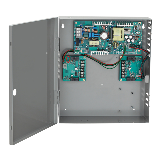
PS914 Power Supply
Pages 1-3
PS914 Power Supply Specifi cations:
Input
Enclosure
Temperature Range
Fuse
Compliance
Compatible Boards
(Optional, 2 boards maximum)
Fire Alarm Input Board (Optional) 900-FA (Requires one option board above)
Battery Backup Board (Optional)
AC Monitor Output
900-2RS Specifi cations:
Inputs I1,I2
Outputs O1,O2
Board Input Power
Temperature Range
Compliance
Fire Alarm Input
© 2010 Ingersoll-Rand Company
1-877-671-7011
44487056 Rev. 10/10_a
PS914 Power Supply
900-KL Keylock
(optional)
Page 2
120/240 VAC, 1.4 A, 50/60Hz, High Voltage Class 1 Wiring Required
4 Amp DC @ 12/24 VDC
May be used to power Von Duprin & Falcon EL device at 24VDC, 16A, 300ms
14" H x 12" W x 4" D (8 knockouts, 1/2" or 3/4" )
32°-120° F (0°- 49° C)
F1, T6.3A
250 VAC
For protection against risk of fi re, replace fuse with same type and rating
UL 294, ULC-S318, RoHS, & FCC Part 15, Class 2 Output
900-2RS
900-2Q
900-4R
900-4RL
900-8F
900-8P
900-BB
Form C Contacts, 30 VDC, 1 Amp, Resistive Load
Dry contacts required (Closed = Active)
Connect control contacts between SC (Signal Common) and any input
• 12/24VDC, 3A (wet) when AC powered • 9.6-13.2VDC or 19.2-26.4VDC when battery powered
• May be used with PS914 to power EL device at 24VDC, 16A, 300ms
• Maximum load cannot exceed power supply ratings or 3A for outputs combined
Board requires 0.1A max. of power supply output current to operate
32°-120° F (0°- 49° C)
UL 294, ULC-S318, RoHS, & FCC Part 15
Accepts 900-FA Fire Alarm Board (Optional)
To avoid risk of electric shock, turn off AC power
before installing or servicing PS914 power supply.
(optional)
Page 3
CAUTION:
!
INST. INSTRUCTIONS - 44487056
INST. INSTRUCTIONS - 44487098
INST. INSTRUCTIONS - 44487106
INST. INSTRUCTIONS - 44487080
INST. INSTRUCTIONS - 44487106
INST. INSTRUCTIONS - 44487106
INST. INSTRUCTIONS - 44487072
INST. INSTRUCTIONS - 44487064
Installation
Instructions
DANGER:
!
900-2RS (optional) - Page 4
(2 Zone EL Control -
Individual/Sequential)
1 of 4
Advertisement
Table of Contents

Related Manuals for Von Duprin PS914

Summary of Contents for Von Duprin PS914
- Page 1 120/240 VAC, 1.4 A, 50/60Hz, High Voltage Class 1 Wiring Required Output 4 Amp DC @ 12/24 VDC May be used to power Von Duprin & Falcon EL device at 24VDC, 16A, 300ms Enclosure 14” H x 12” W x 4” D (8 knockouts, 1/2” or 3/4” ) Temperature Range 32°-120°...
- Page 2 MOUNTING NOTES The PS914 must be installed in accordance with the article 760 of the National Electrical Code or NFPA 72, Canadian Electrical Code, or any other applicable codes. Install the PS914 indoors within the protected premises. Check national and local codes for additional installation requirements.
- Page 3 PS914 SETUP AND TESTING Connect AC Wiring DANGER: AC Input Green (Ground) Ensure AC AC (In) White (Neutral) Breaker is 120/240 Black (Hot) Turned Off 900-BB Connector DANGER High Voltage If main board must be Use Jumper to Select Use Jumper to Select...
- Page 4 (max. ft) IF PS-914 HAS OTHER OPTION BOARDS, SEE THEIR INSTRUCTIONS 1200 Using EL device with EPT or Door Loop (PS914 required) NOTE: WHEN INSTALLATION IS COMPLETE, SECURE ENCLOSURE Using EL device with Electric Hinge/Pivot (PS914 required) DOOR WITH SCREWS OR KEYLOCK...
- Page 5 • Form C contacts rated 30VDC, 3A (Dry) • 12/24VDC, 3A (Wet) when AC powered • 9.6-13.2VDC or 19.2-26.4VDC when battery powered • May be used with PS914 to power EL device at 24VDC, 16A, 300ms • Maximum load cannot exceed power supply ratings or 6A for outputs combined Board Input Power Board requires 0.18A max.
-
Page 6: Table Of Contents
CHOOSE FUNCTION OF 900-4RL BOARD BY SETTING SW2 DIP SWITCHES Four Zone Controller Function (4TD): Controls up to four inputs and four outputs with time delay. This is the default setting. Function LED will blink one time every 5 seconds Auto Operator Function (AO): Coordinates the unlocking of one or two zones with the signaling of an auto operator. -
Page 7: Table Of Contents
- SET TIME DELAY USING SW1 DIP SWITCHES Summary of Operation • Output turns “ON” when input is activated (closed). • Time delay begins when input is released (opened). • Locking Device output will remain “ON” during time delay. • If I1-I4 inputs are wired together, outputs will sequence. DIP switches on SW1 can be turned “ON”... - Page 8 - WIRING EXAMPLE - FAIL SECURE PS914 120/240 VAC x 4RL 50/60Hz EPT 2 or 10 EPT 2 or 10 EL Device 4 EL Device 2 Access (not polarized) Access (not polarized) Control 4 Control 2 EPT 2 or 10...
-
Page 9: Output
- SET CONFIGURATION USING SW1 SWITCHES DIP switches on SW1 can be turned “ON” by moving them in the direction that the arrow is pointing. Switches below shown in “OFF” position OF F 1 2 3 4 5 6 7 8 12345678 SW1 SWITCH AO DIP SWITCH DEFINITIONS... - Page 10 - WIRING EXAMPLE - TWO SINGLE DOORS Summary of Operation For each door, access control input unlocks door. Latch monitor (LX) triggers auto operator. PS914 120/240 VAC Single Door Board Confi guration x 4RL 50/60Hz O FF 1. Position jumpers for dry contact for outputs 2 and 4 (see page 2).
- Page 11 12 or 24VDC (AWG) (Amps DC) (max. ft) (max. ft) Max. ft = one way distance between power supply and device 1200 Using EL device with EPT or Door Loop (PS914 required) Using EL device with Electric Hinge/Pivot (PS914 required)
- Page 12 - WIRING EXAMPLE - 2 TO 6 DOOR INTERLOCK, NORMALLY LOCKED SI Confi guration 1.Turn on switches 1, 2, 4, 5, and 6 on SW1. 2. Install 2 doors per SI board. PS904 120/240 VAC 3. Add up to 2 additional SI boards for a total x 4RL 50/60Hz of 6 door interlock per power supply:...
- Page 13 Installation 900-FA Fire Alarm Input Instructions 44487072 Input (Fire Alarm) Dry contacts required (Closed = no fi re alarm) Connect control contacts between FA1 and FA2 Output (Supervision) 30VDC, 1A resistive dry contact Board Input Power Board requires 0.05A max. of power supply output current to operate Temperature Range 32°-120°...
- Page 14 IF INSTALLING TO PS902 MAIN BOARD Remove Jumper Install 900-FA Here Note: Complete power failure shall result in a fail safe operation. When connected to a fire alarm releasing control unit, total loss of power for the locking mechanisms shall be configured for a fail safe operation.
- Page 15 Other types may burst, causing personal injury and damage. Observe the proper polarity when connecting the batteries. Refer to installation instructions for compatible supply models - PS902, PS904, PS906, and PS914. INSTALL 900-BB ONTO MAIN CIRCUIT BOARD AND SECURE WITH SCREW Plug Connector...
- Page 16 INSTALL AND CONNECT BATTERIES Battery Supervision Terminals Turn On AC Breaker to (Form C Dry Contacts) Energize Power Supply (Shown AC Off) Place Batteries in Box with Terminals to the Left Active Inactive AC On AC Off Attach Wires from Battery Board Red wires = (+) BB LED Black wires = (-)
- Page 17 Installation 900-FA Fire Alarm Input Instructions 44487072 Input (Fire Alarm) Dry contacts required (Closed = no fi re alarm) Connect control contacts between FA1 and FA2 Output (Supervision) 30VDC, 1A resistive dry contact Board Input Power Board requires 0.05A max. of power supply output current to operate Temperature Range 32°-120°...
- Page 18 IF INSTALLING TO PS902 MAIN BOARD Remove Jumper Install 900-FA Here Note: Complete power failure shall result in a fail safe operation. When connected to a fire alarm releasing control unit, total loss of power for the locking mechanisms shall be configured for a fail safe operation.
- Page 19 Other types may burst, causing personal injury and damage. Observe the proper polarity when connecting the batteries. Refer to installation instructions for compatible supply models - PS902, PS904, PS906, and PS914. INSTALL 900-BB ONTO MAIN CIRCUIT BOARD AND SECURE WITH SCREW Plug Connector...
- Page 20 INSTALL AND CONNECT BATTERIES Battery Supervision Terminals Turn On AC Breaker to (Form C Dry Contacts) Energize Power Supply (Shown AC Off) Place Batteries in Box with Terminals to the Left Active Inactive AC On AC Off Attach Wires from Battery Board Red wires = (+) BB LED Black wires = (-)
Need help?
Do you have a question about the PS914 and is the answer not in the manual?
Questions and answers