Table of Contents
Advertisement
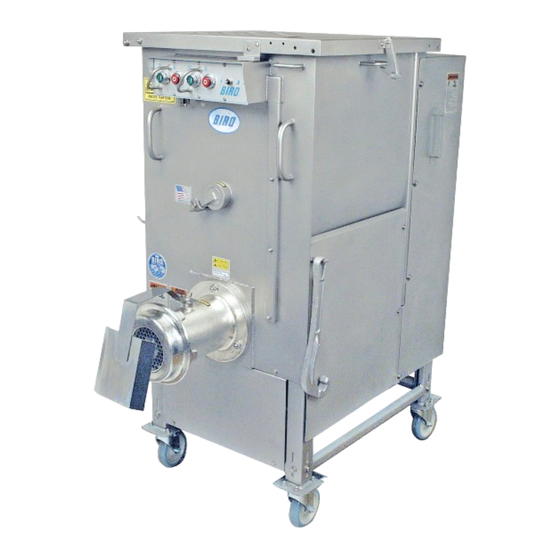
Model AFMG-52 AUTOMATIC FEED MIXER GRINDER
OPERATING AND SERVICE MANUAL
STARTING WITH SERIAL NO. 52001
STARTING WITH SERIAL NO. 52101
(SIDE OPENING LID)
STARTING WITH SERIAL NO. 52345
(35 ° INLET/TRI DIRECTIONAL LID)
IMPORTANT NOTICE
This Manual contains important
safety instructions which must
be strictly followed when using
this equipment.
Item No. 57037
Form No. AFMG52-232-6-17-18 B
Advertisement
Table of Contents

Related Manuals for BIRO AFMG-52


Summary of Contents for BIRO AFMG-52
- Page 1 Model AFMG-52 AUTOMATIC FEED MIXER GRINDER OPERATING AND SERVICE MANUAL STARTING WITH SERIAL NO. 52001 STARTING WITH SERIAL NO. 52101 (SIDE OPENING LID) STARTING WITH SERIAL NO. 52345 (35 ° INLET/TRI DIRECTIONAL LID) IMPORTANT NOTICE This Manual contains important safety instructions which must be strictly followed when using this equipment.
-
Page 2: Table Of Contents
TABLE OF CONTENTS: PAGE NOTICE TO OWNERS AND OPERATORS ..........SAFETY TIPS . -
Page 3: Notice To Owners And Operators
No one should use or service this machine without proper training and supervision. All operators should be thoroughly familiar with the procedures contained in this Manual. Even so, BIRO cannot anticipate every circumstance or environment in which its products will be used. You, the owner... -
Page 4: Safety Tips
NEVER Alter This Machine From its Original Form as Shipped From Factory. DO NOT Operate Machine With Missing Parts. • PROMPTLY REPLACE Any Worn or Illegible Warning Labels. • ALWAYS Read Operation and Service Manual BEFORE Operating, Cleaning, or Servicing. • USE ONLY BIRO Parts and Accessories Properly Installed. -
Page 5: Installation
1. Read this Manual thoroughly before installation and operation. Do not proceed with installation and operation if you have any questions or do not understand anything in this Manual. Contact your local Distributor, or BIRO first. 2. Remove all banding, shipping carton, and all equipment from inside the tub. Then take machine off shipping pallet. -
Page 6: Motor Wiring And Electrical Requirements
9. The recommended amp service size for the mixer grinder with a 7½ HP, 400V grind motor is 40 Amp service. With a 10 HP, 400V grind motor is 50 Amp service. 10. The BIRO Manufacturing Company is not responsible for permanent wiring, connection or installation. 3-PHASE MOTOR SPECIFICATIONS AND OVERLOADS... - Page 7 16. Check placement of all warning labels and Manual. Machine is now ready for trained operators to process product. 17. Use meat deflector attached to grinding bowl to eliminate meat splatter. 18. Contact your local Distributor or BIRO directly if you have any questions or problems with the installation or operation of this machine.
-
Page 8: Operation
OPERATION ROTATING GRINDING AUGER & ROTATING MIXING PADDLE TO AVOID SERIOUS PERSONAL INJURY • ONLY Properly Trained Personnel Should Use This Equipment. • NEVER Place Hands into Machine Input or Output Openings. • NEVER Open Machine During Operation. • DO NOT Wear Gloves While Operating. •... -
Page 9: Cleaning
• ALWAYS Thoroughly Clean Equipment at Least Daily. CLEANING THE BIRO MIXER-GRINDER l. Disconnect mixer grinder from power-source and perform lockout/tagout procedures. 2. Remove grinding bowl end ring, breaker plate, knife and grinding auger. Care is needed when handling the knife. -
Page 10: Maintenance
PROMPTLY REPLACE Any Worn or Illegible Warning Labels. • USE ONLY GENUINE BIRO Parts and Accessories Properly Installed. A. GRINDING BOWL INSTALLATION 1. Mount the grinding bowl on the three threaded studs on the front of the machine. Tighten in position with provided nuts. -
Page 11: Nord Transmission
OPERATING AND MAINTENANCE INSTRUCTIONS STARTING WITH SERIAL No. 57181 3. FOR NORD HELICAL-WORM GEAR AND MOTOR REDUCER ELECTRICAL CONNECTIONS NORD GEAR CORP. Check the motor nameplate to verify the phase, hertz and voltage agrees 800 Nord Drive P.O. Box 376 with the available power supply. - Page 12 INSTRUCTIONS FOR MOUNTING NEW 1-PIECE NORD GEAR REDUCER/GEAR MOTOR 1. Disconnect and unplug from main power source and perform lockout/tagout before attempting to service. 2. Remove rear cover. 3. Remove junction box cover from 1HP motor, disconnect the lead wires from the mixer motor. Loosen the strain relief and pull the cord thru, attach blue ring terminals to black, white, red and green wires.
-
Page 13: Dorris Transmission
4. FOR DORRIS MIXER TRANSMISSION (OBSOLETE -N/A) BEFORE SERIAL NO. 55665 BREATHER PLUG DORRIS MIXER TRANSMISSION: Oil in the mixer transmission should be changed after the first four (4) weeks LEVEL of operation. This is to remove the “run in” oil and also any PLUG small metal shavings that may have been generated during the initial mating of the gears. -
Page 14: Mixer Drive Chain Tension
MAIN DRIVE CHAIN AND SPROCKET LUBRICATION (continued): Recommended types of chain lubricant are those with Molybdenum Disulphide or Graphite added. Also bonded lubricants such as Dow Corning Molykote 321R or equivalent are excellent for open chains. The lubricant should be of a viscosity whereby it will “flow” somewhat and penetrate the internal working surfaces. -
Page 15: Mixer Drive Shaft Seal Replacement
11. Wait, allow for 10 minutes set up time. Remove Wedge and Ring. 12. Apply a small amount of NSF approved silicone sealant, Biro Item No. 400 around the outside edge of the Seal. Wipe away excess silicone sealant. The 3 fluid ounce tube of Sealant contains enough to complete 30 Assemblies. -
Page 16: Optional Eagle Belt Drive System
OPTIONAL EAGLE BELT DRIVE SYSTEM... -
Page 17: Supply Cord Replacement
“EAGLE” DRIVE BELT Tensioning Instructions 1. Place a straight edge on top of the belt and across both sprockets as shown in the diagram. 2. Set the large O-Ring at the 1 Graduation ( ⅛” line) on the Tension Tester, Item No. -
Page 18: Parts Diagrams
AFMG-52 SIDE VIEW PARTS DIAGRAM 1, 1A, 1B 46,47 42,44 48,49 SEE ABOVE PADDLE DETAIL (NOT SHOWN) - Page 19 BIRO MODEL AFMG-52 MIXER GRINDER PARTS LIST Fig. Item No. Description Fig. Item No. Description HHS055S 57154 Product mixer safety cover, tri directional Hex head screw, -18 x ¾, SS HN07S Hex nut, 10-24, SS #52345 on HN15S Hex nut, ¼-20, SS...
- Page 20 AFMG-52 MIXER GRINDER PARTS LIST WITH NORD 32, 33, 34 2, 2A, 2B, 2C GEAR TRANSMISSION STARTING WITH SERIAL No. 57181 3, 4, 6 27, 28, 29, 30, 31 5, 5A, 5B 10, 10A 13, 13A 15, 15A, 15B 19, 19A, 19B Fig.
-
Page 21: Standard And Optional Bowl Assemblies
STANDARD “ENTERPRISE” BOWL ASSEMBLY (SINGLE KNIFE & SINGLE PLATE) Item No. Description 54278B Square drive auger adapter 54278C Auger shear pin 57022-CTN Auger assembly complete 57023-CTN Bowl with plate pins FHS36S Shear pin fasteners ¼-20 x 1, SS HK52/56 Knife drive pin, coarse thread HP52 Bowl plate pin ( 3 req.) HR52... -
Page 22: Product Mixer Safety Covers & Lid Locks
PRODUCT MIXER SAFETY COVER UP TO S/N 52100 FRONT OPENING ONLY BACK VIEW RIGHT SIDE VIEW Fig. Item No. Description Fig. Item No. Description ¼ 53446 FW06S Flat washer , SS (2 ea.) Lid assembly, up to #52100 ⅜ HN30S 56072 Hex nut -16, SS (2 ea.) -
Page 23: Journal Box
ITEM No. 53886 JOURNAL BOX ASSEMBLY 53888 53785 53785 53889 53609 not shown Item No. Description 53886 Journal box assembly 53609 Journal box housing 53724 Auger drive shaft 53785 Journal box seal (2 ea.) 53888, 53940 Front bearing cup/cone assembly Use H310A 53889, 53939 Rear bearing cup/cone assembly... -
Page 24: Items Required For Tandem Operation Up To S/N 52344
ITEMS REQUIRED BIRO MANUAL TO BIRO AFMG-52 FOR TANDEM OPERATION BIRO AFMG-52 TO BIRO AFMG-48 USED ON ALL UNITS UP TO SERIAL No. 52344 BIRO AFMG-52 TO BIRO AFMG-52 PLEASE NOTE - THESE ARE DESIGNED TO WORK ON BIRO EQUIPMENT ONLY ITEM No. - Page 25 TANDEM OPERATION ILLUSTRATION FOR 90° INLET AFMG-52 OPTIONAL 15” LEFT SIDE APPROX. INLET FEED AFMG-52 TUBE APPROX. 6 FOOT OVERALL 1” OPTIONAL LEFT SIDE INLET FEED AFMG-52 TUBE BIRO 3, 5, 7 HP GRINDERS 15” 46” 1” 19” APPROX. 9”...
-
Page 26: Items Required For Tandem Operation After S/N 52345
ITEMS REQUIRED BIRO MANUAL TO BIRO AFMG-52 FOR TANDEM OPERATION BIRO AFMG-52 TO BIRO AFMG-48 STARTING WITH SERIAL No. 52345 BIRO AFMG-52 TO BIRO AFMG-52 PLEASE NOTE - THESE ARE DESIGNED TO WORK ON BIRO EQUIPMENT ONLY 52 SIZE DISCHARGE HORN ASSEMBLY Item No. -
Page 27: Connection Instructions For Tandem Operation
CONNECTION INSTRUCTIONS FOR TANDEM OPERATIONS AFMG-48 or AFMG-52 INTO AFMG-48 or AFMG-52 Heavy Horsepower Grinder INTO AFMG-48 or AFMG-52 Step 1. Remove Lock Knobs, Item No. 14688; Outer disc, Item No. 54303 and Side Entrance Seal, Item No. 57133 from the inlet tube of the Second Grind Machine. Clean out the tube if necessary. - Page 28 TANDEM OPERATION ILLUSTRATION FOR 35° INLET...
-
Page 29: Wiring Diagram
WIRING DIAGRAM... -
Page 30: Safety Label Locations
SAFETY LABEL LOCATIONS CAUTION KEEP HANDS OUT OF HOPPER DO NOT TAMPER, BYPASS, REMOVE ANY SAFETY INTERLOCK SWITCHES OR OTHER SAFETY DEVICES. ALWAYS DISCONNECT POWER SUPPLY BEFORE REMOVING SHROUDS, GUARDS, COVERS, DOORS, FENCES, PANELS, FOR CLEANING, SERVICING, REASSEMBLING, OR ANY REASON. FAILURE TO COMPLY WITH WARNING COULD RESULT IN SERIOUS BODILY INJURY. -
Page 31: Operator's Signature Page
OPERATOR’S SIGNATURE PAGE WARNING READ AND UNDERSTAND THIS ENTIRE MANUAL BEFORE SIGNING BELOW MY SIGNATURE ATTESTS THAT I HAVE COMPLETELY READ AND UNDERSTAND THIS MANUAL. I REALIZE THAT THIS MACHINE, IF OPERATED CARELESSLY, CAN CAUSE SERIOUS INJURY TO MYSELF AND OTHERS. NAME (PRINT) SIGNATURE SUPERVISOR’S... -
Page 32: Limited Warranty
BIRO is not responsible for service charges or labor required to replace any part covered by this limited warranty or for any damages resulting from misuse, abuse, lack of proper or recommended service.
Need help?
Do you have a question about the AFMG-52 and is the answer not in the manual?
Questions and answers