Table of Contents
Advertisement
Quick Links
Advertisement
Table of Contents
Troubleshooting

Related Manuals for Hubbell T1000


Summary of Contents for Hubbell T1000
- Page 1 OPERATING AND MAINTENANCE MANUAL FOR T1000 CONTROLLER ELECTRIC HEATER COMPANY...
-
Page 2: Controller Description
CONTROLLER DESCRIPTION CONTROL BOARD AND DISPLAY The control board supplies all the necessary function for heater operation. These include control temperature, hi-limit cut-out, low water detection, and leak detection. CONTROLLER OPERATION NOTE: All controller variables come preset from the factory to include a preset temperature of 185°F. 1. - Page 3 iv. Temperature units – sets the temperature units to either degrees Fahrenheit or Celsius. 1. DEF, for degrees Fahrenheit. (Factory Default) 2. DEC, for degrees Celsius. v. Differential – sets the number of degrees below setpoint that the heater will resume heating after it has achieved setpoint.
-
Page 4: Wiring Options
2. This alarm can be wired to the J4 connector on the control board as shown below. To facilitate this installation, an optional adapter, Hubbell P/N PLUG ADAPTER J4, can be purchased to provide wire connections. J4 Connnector... -
Page 5: Troubleshooting
TROUBLESHOOTING ERROR MESSAGES 1. Err, No, Prb a. This message will flash when the controller does not detect that the probe is connected to the control board. To clear this error reinsert the probe connector and press RESET. If the error message does not clear, replace the probe assembly. 2. -
Page 6: Troubleshooting Flowcharts
Verifythat all wires Magnetic are installed and in 208/240V contactor pull correct positions at contactor Replace contactor (see wiring coil? diagrams) Verify T1000 configuration settings. Replace control board, if Correct fault needed condition Correct amps Replace faulty Contact factory at elements? - Page 7 Are configuration Continuous Correct settings set properly, over-temperature contactors pull out temperature per Section III, Para. condition at setpoint? setpoint? Is there zero amp draw when the contactors drop out at setpoint? Properly set temperature Diagram 3 setpoint White Black Is there 208/240V across Contact factory...
- Page 8 Is the circuit Reset circuit No Display breaker tripped at breaker source? Is the circuit breaker tripped Reset circuit inside heater breaker (if supplied)? Press ON/OFF button on heater Is correct voltage measured at power Check incoming distribution block or line power side of contactor for each phase?
-
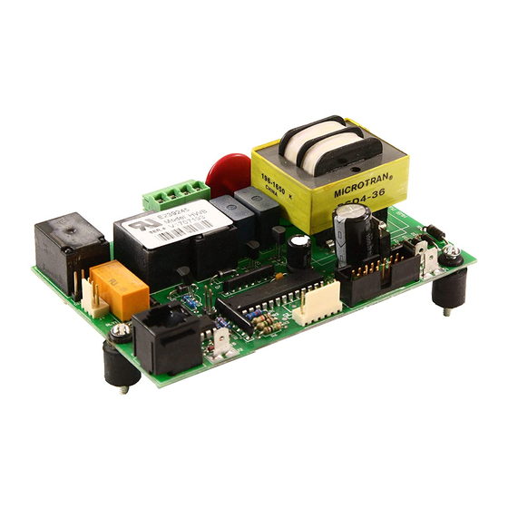
Page 9: Control Board
SERVICING CONTROL BOARD 1. Disconnect power from unit. 2. Disconnect display cable, probe cable (J3), leak detection wire (J2), ground wire (J7), and terminal block (J5) from the control board. NOTE: The terminal block (J5) is removable from the control board. Grasp the terminal block on the ends and pull straight away from the board. -
Page 10: Sensor Probe
NOTE: Care should be taken not to pull or put excessive force on the cable to probe connection. 8. Install new #115 Buna-N o-ring gasket and install new probe. NOTE: Hubbell recommends lubricating the o-ring with Parker O-Lube prior to installation. WARNING: Do not remove the jam nut.
Need help?
Do you have a question about the T1000 and is the answer not in the manual?
Questions and answers